Loch
Loch Eck WTW - Water Projects Online
Loch Eck WTW - Water Projects Online
- No tags were found...

Create successful ePaper yourself
Turn your PDF publications into a flip-book with our unique Google optimized e-Paper software.
Water Treatment and Supply<br />
<strong>Loch</strong> Eck Water Treatment Works<br />
£8.4 investment improves quality<br />
by<br />
Garvie Murray & James Strapp<br />
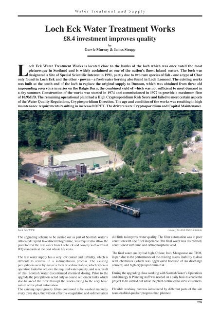
<strong>Loch</strong> Eck Water Treatment Works is located close to the banks of the loch which was once voted the most<br />
picturesque in Scotland and is widely acclaimed as one of the nation’s finest inland waters. The loch was<br />
designated a Site of Special Scientific Interest in 1991, partly due to two rare species of fish - one a type of Char<br />
only found in <strong>Loch</strong> Eck and the other - powan - a freshwater herring also found in <strong>Loch</strong> Lomond. The existing works<br />
was built at the south end of the loch to replace the original supply to Dunoon, which was obtained from three old<br />
impounding reservoirs in series on the Balgie Burn, the combined yield of which was not sufficient to meet demand in<br />
a dry summer. Construction of the works was started in 1974 and commissioned in 1977 to provide a maximum flow<br />
of 10.9Ml/D. The remaining operational plant had a High Cryptosporidium Risk Score and failed to meet certain aspects<br />
of the Water Quality Regulations, Cryptosporidium Direction. The age and condition of the works was resulting in high<br />
maintenance requirements resulting in increased OPEX. The drivers were Cryptosporidium and Capital Maintenance.<br />
Lock Eck WTW<br />
The upgrading scheme to be carried out as part of Scottish Water’s<br />
Allocated Capital Investment Programme, was required to allow the<br />
plant to treat the raw water from <strong>Loch</strong> Eck and comply with relevant<br />
WQ standards at the best whole life costs.<br />
The raw water supply has a very low colour and turbidity, which is<br />
difficult to remove in a sedimentation process. The existing<br />
precipitators were by nature a form of sedimentation, which when in<br />
operation failed to achieve the required water quality, and as a result<br />
of this, Scottish Water discontinued chemical dosing. Prior to the<br />
upgrade the precipitators acted only as coarse settlement tanks which<br />
also balanced the flow through the works owing to the very basic<br />
nature of the plant automation.<br />
The existing rapid gravity filters continued to be washed manually<br />
every three days, but without effective coagulation and sedimentation<br />
courtesy Scottish Water Solutions<br />
did little to improve water quality. The filter automation was in poor<br />
condition with one filter inoperable. The final water was disinfected,<br />
conditioned with lime and orthophosphoric acid.<br />
The final water quality had high, Colour, Iron, Manganese and THM,<br />
in part due to the performance of the existing assets, inability to dose<br />
with chemicals (which was aggravated because of no discharge<br />
consent) and high cryptosporidium risk.<br />
During the upgrading close working with Scottish Water’s Operations<br />
and Strategy & Planning staff was needed on a daily basis to enable the<br />
project to be carried out while the plant continued to serve customers.<br />
Flexible working patterns introduced by different parts of the site<br />
team enabled quicker progress than planned.<br />
209
Water Treatment and Supply<br />
Solution<br />
A detailed value scoping and value analysis programme was<br />
undertaken to devise a suitable plant design to not only meet the<br />
required output for Lock Eck but also to account of all site constraints.<br />
The agreed output from these exercises was a chemical<br />
coagulation plant, utilising direct filtration with an additional<br />
separate washwater recovery/sludge treatment system<br />
incorporating sludge thickeners, sludge storage and a recessed<br />
plate press.<br />
Chemical systems handling and dosing systems were to be<br />
upgraded/provided. Where practical the upgrade was to<br />
integrate with and utilise existing assets.<br />
The processes were to be fully automated with integral PLCs and<br />
SCADA systems.<br />
Inlet works<br />
The inlet works were designed to allow the water flowing forward to<br />
be of uniform quality, allowing further treatment of the raw water,<br />
plus any returned water, in the subsequent treatment processes. The<br />
return liquors from the sludge thickeners are fed into the raw water<br />
stream, just after the inlet-balancing tank.<br />
The addition of chemicals is immediately upstream of the associated<br />
mixing facility with Lime, Alum and Polyelectrolyte (poly) dosed in<br />
that order. Duty and standby dosing points are provided for both<br />
Alum and Lime: duty only will be provided for the Poly as it is not<br />
deemed as critical to the overall process.<br />
Two dosing points (duty/standby) were provided for each chemical.<br />
The design incorporated sufficient time to allow the coagulation<br />
process to be completed prior to downstream treatment over the<br />
expected range of temperatures,<br />
Filtration<br />
The filters, supplied by AMT Systems, were designed on the constant<br />
flowrate principle with filter inlet channel levels used to derive a filter<br />
flow set point, which is then used to maintain the same flow through<br />
all filters via the filter outlet control valve.<br />
When preparing for backwash, filters drain to service at the same rate<br />
as the operating filters unless the increase in filter output jeopardises<br />
downstream processes. In such a case, the drain down rate is suitably<br />
limited.<br />
The design allows for the backwashing of individual filters to be<br />
staggered over as long a period as possible. The backwashing system<br />
is designed to minimise the long-term loss of filter media to no more<br />
than 3% annually and minimise any increase in filter start up head loss.<br />
Filtration system<br />
The filtration system uses the existing six filters. The area of each<br />
filter is 16.775m 2 and the total media depth needed to meet the<br />
required water quality output is 1.3m made up of 800mm of sand<br />
with 500mm of grade 2 anthracite.<br />
Dirty Washwater Recovery/Sludge Treatment<br />
The normal washwater recovery system is through the thickeners<br />
directly from the washwater recovery tank. The flow to the head of<br />
the works will be continuous and controlled to less than 10% of the<br />
raw water intake. To meet the quality requirements there are two<br />
thickeners operating on a duty/standby basis. The sludge is thickened<br />
with polyelectrolyte. The thickeners are sized to take the maximum<br />
hydraulic load through the works.<br />
There is also a facility to utilise in an emergency the existing sludge<br />
lagoons on site. If for any reason the thickener supernatant does not<br />
meet the required turbidity standard and after one fill cycle of the<br />
washwater recovery tank, the flow will be diverted to the existing<br />
sludge lagoons before the standby thickener is changed over to duty.<br />
Thickened sludge from the duty thickener is transferred to a holding<br />
tank before being pressed in the recessed plate press. Sludge cake is<br />
emptied into a skip located under the press, supplied by Andritz Ltd,<br />
before being transferred off site to landfill.<br />
Dirty Washwater Recovery/Sludge treatment system<br />
The recovery system is designed on the basis that the existing<br />
backwash waste water recovery tank will also act as the buffering<br />
tank. The solids are kept in suspension by a mixer inside the tank.<br />
Chemical storage & dosing<br />
A new Aluminium sulphate storage system, coagulation and sludge<br />
poly storage, make-up & dosing systems were installed and the lime<br />
and chlorine dosing systems were upgraded.<br />
IC&A<br />
New water quality instrumentation was installed throughout the<br />
works including three PLC’s with integrated HMI and SCADA<br />
package and a satellite telemetry package.<br />
Timescale<br />
Contractors Galliford Try/Morgan Est Joint Venture (GMJV) began<br />
on site in June 2005 and the project was completed in the summer of<br />
2006. ■<br />
Note: The Editor & Publishers wish to thank the authors, Garvie<br />
Murray, Senior Project Manager, Scottish Water Solutions and James<br />
Strapp, Project Manager, Scottish Water Solutions, for<br />
providing the above article for publication.