Long Reach STW - Water Projects Online
Long Reach STW - Water Projects Online
Long Reach STW - Water Projects Online

Create successful ePaper yourself
Turn your PDF publications into a flip-book with our unique Google optimized e-Paper software.
www.<strong>Water</strong><strong>Projects</strong><strong>Online</strong>.com Wastewater Treatment & Sewerage<br />
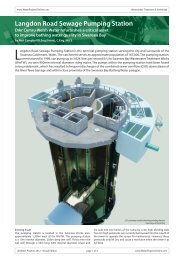
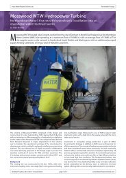
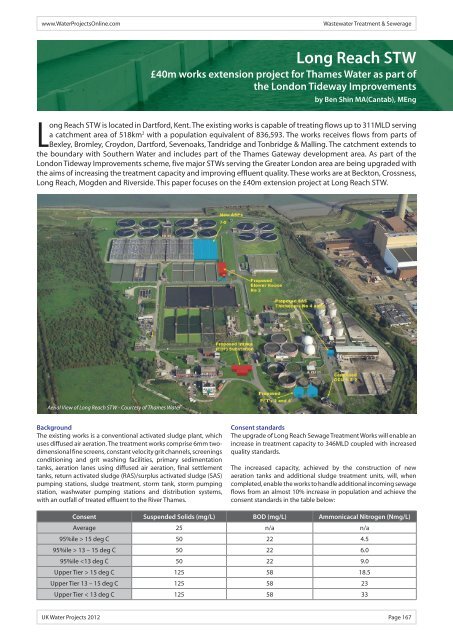
<strong>Long</strong> <strong>Reach</strong> <strong>STW</strong> is located in Dartford, Kent. The existing works is capable of treating flows up to 311MLD serving<br />
a catchment area of 518km 2 with a population equivalent of 836,593. The works receives flows from parts of<br />
Bexley, Bromley, Croydon, Dartford, Sevenoaks, Tandridge and Tonbridge & Malling. The catchment extends to<br />
the boundary with Southern <strong>Water</strong> and includes part of the Thames Gateway development area. As part of the<br />
London Tideway Improvements scheme, five major <strong>STW</strong>s serving the Greater London area are being upgraded with<br />
the aims of increasing the treatment capacity and improving effluent quality. These works are at Beckton, Crossness,<br />
<strong>Long</strong> <strong>Reach</strong>, Mogden and Riverside. This paper focuses on the £40m extension project at <strong>Long</strong> <strong>Reach</strong> <strong>STW</strong>.<br />
Aerial View of <strong>Long</strong> <strong>Reach</strong> <strong>STW</strong> - Courtesy of Thames <strong>Water</strong><br />
Background<br />
The existing works is a conventional activated sludge plant, which<br />
uses diffused air aeration. The treatment works comprise 6mm twodimensional<br />
fine screens, constant velocity grit channels, screenings<br />
conditioning and grit washing facilities, primary sedimentation<br />
tanks, aeration lanes using diffused air aeration, final settlement<br />
tanks, return activated sludge (RAS)/surplus activated sludge (SAS)<br />
pumping stations, sludge treatment, storm tank, storm pumping<br />
station, washwater pumping stations and distribution systems,<br />
with an outfall of treated effluent to the River Thames.<br />
<strong>Long</strong> <strong>Reach</strong> <strong>STW</strong><br />
£40m works extension project for Thames <strong>Water</strong> as part of<br />
the London Tideway Improvements<br />
by Ben Shin MA(Cantab), MEng<br />
Consent standards<br />
The upgrade of <strong>Long</strong> <strong>Reach</strong> Sewage Treatment Works will enable an<br />
increase in treatment capacity to 346MLD coupled with increased<br />
quality standards.<br />
The increased capacity, achieved by the construction of new<br />
aeration tanks and additional sludge treatment units, will, when<br />
completed, enable the works to handle additional incoming sewage<br />
flows from an almost 10% increase in population and achieve the<br />
consent standards in the table below:<br />
Consent Suspended Solids (mg/L) BOD (mg/L) Ammonicacal Nitrogen (Nmg/L)<br />
Average 25 n/a n/a<br />
95%ile > 15 deg C 50 22 4.5<br />
95%ile > 13 – 15 deg C 50 22 6.0<br />
95%ile 15 deg C 125 58 18.5<br />
Upper Tier 13 – 15 deg C 125 58 23<br />
Upper Tier < 13 deg C 125 58 33<br />
UK <strong>Water</strong> <strong>Projects</strong> 2012 Page 167
www.mwhglobal.com<br />
Our product portfolio...<br />
...of water and sewage equipment is amongst<br />
the most comprehensive in the industry.<br />
Providing high quality treatment equipment<br />
along with the refurbishment and upgrade of<br />
existing equipment.<br />
info@mwhglobal.com
Wastewater Treatment & Sewerage www.<strong>Water</strong><strong>Projects</strong><strong>Online</strong>.com<br />
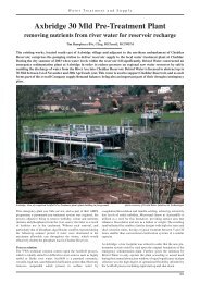
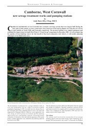
3D modelling of channel connection at ASP - Courtesy of Mott MacDonald ASP underside channel connection - Courtesy of Mott MacDonald<br />
Project team<br />
For the detailed design and subsequent construction, Thames<br />
<strong>Water</strong> engaged GBJV, who were assisted by Mott MacDonald. GBJV<br />
is a joint venture between Galliford Try Infrastructure and MWH<br />
Treatment (formerly Biwater Treatment). MWH and Mot MacDonald<br />
are responsible for all design including process, mechanical,<br />
electrical and civil engineering as well as environmental advice<br />
such as contaminated ground assessment and landscaping.<br />
The upgrade<br />
The extended treatment being constructed under this project<br />
comprises 3 (No.) aeration lanes, a new blower house, refurbishment<br />
and upgrade of the existing blower house, 2 (No.) additional picket<br />
fence thickeners, 2 (No.) additional belt thickeners, additional<br />
standby power generation and fuel tank, upgrading the existing<br />
12 (No.) FST scrapper bridges, a new substation, and a new SCADA<br />
system.<br />
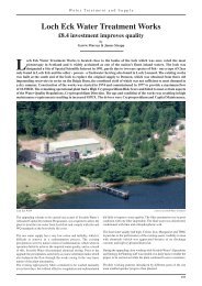
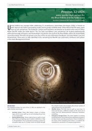
Aeration lanes<br />
The new aeration lanes are designed to work in parallel with the<br />
existing 6 (No.) shallower aeration lanes. Each new lane is 8.3m<br />
wide, 80m long and 6m deep and comprises a two pass system with<br />
upstream anoxic zone, and is equipped with two point dissolved<br />
New Aeration Tank undergoing water test<br />
Courtesy of Mott MacDonald<br />
oxygen control. A pumped mixing system is being installed within<br />
the existing return activated sludge (RAS) channels to ensure even<br />
loading of RAS solids back to the new and existing aeration lanes.<br />
Connection of the existing lanes to the new lanes is complex and<br />
involves extending the existing channels, namely RAS, settled<br />
sewage and return liquors.<br />
In the past, the existing base slab of Tank 6 protruded further<br />
than the existing wall, which was intended to simplify future<br />
extension with the protrusion forming part of the new floor. The<br />
liquor channels also extend further than the existing tank with a<br />
part-masonry vertical section intended to form a future weir and<br />
connection. However, for modern efficient aeration, the new lanes<br />
are designed to be 2m deeper than the original ones which render<br />
the mentioned arrangement a hindrance rather than convenience.<br />
Because of this, the 3 (No.) new aeration lanes were sited slightly<br />
further away from the existing structure and designed as a standalone<br />
structure.<br />
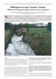
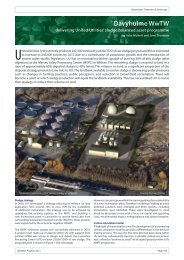
The critical challenge involved the extension of the channels. The<br />
new ones were constructed off line as future extensions of the<br />
existing channels, while the actual connection would only be made<br />
during a brief shut-down period when the existing channels could<br />
Aeration tank under construction<br />
Courtesy of Mott MacDonald<br />
Page 168 UK <strong>Water</strong> <strong>Projects</strong> 2012
www.<strong>Water</strong><strong>Projects</strong><strong>Online</strong>.com Wastewater Treatment & Sewerage<br />
be drained down. It was a significant structural challenge because<br />
a multidirectional movement joint was required to accommodate<br />
for any future differential movement whilst maintaining water<br />
tightness. This was further complicated by a large diameter pipe<br />
(2.5m ID) right underneath the connection which made piling<br />
impossible. The required connecting piece was therefore designed<br />
as a cantilever. The existing channel walls also feature a tapered<br />
section while linear sections were specified in the new channels<br />
in order to ease construction. The transition from the tapered<br />
section to the linear section was geometrically complex. Extensive<br />
3-dimensional modelling was carried out to aid visualisation and<br />
structural analysis.<br />
The ground investigation confirmed that the groundwater table is<br />
closely related to the tide level to the adjacent River Thames. The<br />
ground was made up mainly of alluvium below made ground and<br />
830 (No.) Driven Cast In-situ (DCIS) piles of 340mm diameter, found<br />
on the River Terrace Deposit below the alluvium, were specified<br />
to support the structure. These piles were also designed to take<br />
tension to help resist flotation in the event of flooding from the<br />
River Darrent nearby or from catastrophic failure of any works<br />
process. Due to the high groundwater table, local dewatering and<br />
a sheet piled cofferdam were also required during the formation of<br />
the base slabs.<br />
Blowers<br />
4 (No.) blowers, arranged on a two duty/two standby basis, were<br />
required to provide the design maximum duty air demand of<br />
28,000m 3 /hr to the new aeration lanes. These blowers were housed<br />
in a structural steel portal frame structure. The original tender<br />
design of this building specified a basement of the same footprint<br />
to house the large diameter air header main towards the aeration<br />
lanes. Significant savings were realised when this feature was<br />
designed out, and the air main was housed in a separate concrete<br />
trough outside the building footprint. Due to the poor ground, the<br />
Mott MacDonald<br />
World leading water solutions<br />
Our skills in the water sector encompass all<br />
aspects of the water cycle, enabling us to work<br />
with our clients to deliver innovative, sustainable<br />
and cost effective solutions that benefit all<br />
stakeholders from governments to end users.<br />
■ Asset management and business planning<br />
■ <strong>Water</strong> resource planning<br />
■ Dams and irrigation<br />
■ <strong>Water</strong> and wastewater networks<br />
■ <strong>Water</strong> and wastewater treatment<br />
■ Treated sewage effluent<br />
■ Sludge treatment<br />
■ Energy from waste<br />
■ <strong>Water</strong> re-use<br />
structure is also found on DCIS piles. However, there are numerous<br />
existing underground services in the area including washwater<br />
and surplus activated sludge pipelines. A concrete encased brick<br />
lined sewer and concrete sludge drying bed – not shown on any<br />
record drawings, stretching back to the Victorian times – were<br />
also discovered in subsequent ground investigation. An irregular<br />
pile grid was introduced in order to avoid all these underground<br />
obstructions. The need for deep trenches within the base slab of<br />
the blower house posed a particular structural design challenge of<br />
the base slab. Extensive three dimensional finite element structural<br />
analyses were carried out in order to optimise the pile location and<br />
reinforcement density. The proliferation of existing services below<br />
the new blower house vindicated the early decision to delete the<br />
basement construction.<br />
As part of the scheme, the blowers in the existing blower house<br />
building were also replaced by 5 (No.) new Howden blowers<br />
arranged on a duty/duty/assist/assist/standby basis to cater for<br />
the increased demand of a design maximum of 88,700m 3 /hr.<br />
Substantial modification of the existing building was necessary to<br />
accommodate the bigger and heavier blowers. Major modification<br />
of existing plinths was required where existing penetrations in the<br />
floor were filled in and new ones formed to accommodate the air<br />
pipe connection into the air main header in the basement area.<br />
Structural assessment was carried out and structural steel frames<br />
were installed to strengthen the floor following detailed analysis<br />
by MM structural engineers. An increase in air intake requirements<br />
meant that new openings were required on the external wall. The<br />
brick work behind the existing louvres was removed to increase<br />
volume of air intake while conserving the architectural features of<br />
the building.<br />
Sludge treatment<br />
The sludge treatment capacity was also increased as part of the<br />
upgrade. 2 (No.) 15m diameter picket fence thickeners were<br />
GAYNOR.DARKE@MOTTMAC.COM WWW.WATER.MOTTMAC.COM<br />
UK <strong>Water</strong> <strong>Projects</strong> 2012 Page 169
Wastewater Treatment & Sewerage www.<strong>Water</strong><strong>Projects</strong><strong>Online</strong>.com<br />
installed to supplement the 2 (No.) existing thickeners. The River<br />
Terrace Deposit below ground in this area is relatively thinner<br />
and it was feared that DCIS piles would be driven through this<br />
layer. Hence continuous flight auger (CFA) piles were specified<br />
for a more accurate depth control. It was identified that there<br />
were pockets of contaminated material in the ground. The Mott<br />
MacDonald environmental team carried out ground assessments<br />
to ensure that the proposed piles did not introduce new paths for<br />
the contaminants to reach the aquifer and developed the waste<br />
disposal strategy to ensure that any contaminated material found<br />
was segregated and identified for removal or storage on site.<br />
Odour control units were also installed to deal with the odours<br />
emanating from the existing and additional sludge storage and<br />
treatment. Significant savings were achieved by providing one<br />
larger capacity OCU system treating all tanks and distribution<br />
chamber compared to the original design where separate OCU<br />
system was to be provided. The odour control system is arranged<br />
in two stages comprising a biofilter first stage with a dry carbon<br />
polishing second stage.<br />
For increased dewatering capacity, 2 (No.) 1.5m wide Ashbrook<br />
Simon-Hartley aquabelt thickeners were provided. Only one<br />
additional thickener was specified at the tender stage and it would<br />
be housed in a kiosk on the hardstanding outside the existing<br />
thickener building next to the entrance. However, the number of<br />
thickeners required was later increased to two after a review by<br />
Thames <strong>Water</strong>. This was particularly challenging because of the lack<br />
of space.<br />
There are also existing concrete encased telecommunication cables<br />
present close to the ground in the area and a 2-level base slab was<br />
developed to avoid this. Extensive tracking modelling was carried<br />
out by the civil engineering designers ensuring that the new<br />
kiosk Kirk Ad does v2 A5L_Layout not obstruct 1 01/06/2012 the maintenance 09:47 Page 1<br />
vehicles accessing the<br />
ENVIRONMENTAL<br />
thickener building. Turning circles of different vehicles including<br />
29T articulated-lorries and 7.5T lorries were accounted for in the<br />
analysis.<br />
Power supply<br />
A new 11kV intake substation was also required, mainly to cater<br />
for the increased air blower load, and would be connected to 2<br />
(No.) 7.5MVA transformers, which in turn, would be connected to<br />
a 3kV intake switchboard. The existing ground levels in the new<br />
substation area vary and there is a 1 in 10 slope towards an access<br />
road. The level of the building was carefully chosen so that the<br />
existing ground level can be built up above the 1 in 100 year flood<br />
level by recycling the piling mat material at the aeration tanks.<br />
The higher level at the substation area also enables roof runoff<br />
to positively drain to the existing drains returning to the head of<br />
works.<br />
Minimising the environmental impact<br />
In order to minimise environmental impacts, all excavated materials<br />
are retained on site. They include excavated materials at the aeration<br />
tanks and the service corridor, piling mat and CFA pile spoils at the<br />
thickener areas and amount to over 37,000m 3 . This was challenging<br />
as there is limited available space in the works and the heights of<br />
bunds are intended to be no more than 2m high stipulated by the<br />
planning authorities. A 3D ground model was developed by Mott<br />
MacDonald to investigate the suitable areas for landscape bunding.<br />
A new tree belt of native species including hornbeam, birch, oak<br />
and ash was introduced on the bunds along the site boundary, by<br />
landscape architects from Mott MacDonald, to help screen the site.<br />
It is expected that the project shall be completed by the end of<br />
2012.<br />
The Editor and Publishers thank Ben Shin, Graduate Engineer with<br />
Mott MacDonald, for preparing this paper for publication.<br />
UK’s Leading Contractor in Anaerobic<br />
Digestion infrastructure<br />
• PERMASTORE ® Glass-fused-to-Steel Tanks & Roofs<br />
• BIODOME ® Double Membrane Gas Holders<br />
• Coated Steel Tanks & Stainless Steel Roofs<br />
• Circular reinforced Concrete Tanks & Foundations<br />
• Major AD construction projects recently completed for<br />
Agricultural, Commercial and Municipal sectors<br />
• Meeting all UK standards for Health & Safety, Quality<br />
and Environmental Controls<br />
• Over 35 years of worldwide installation experience<br />
• Operating in close partnership with all major process<br />
technology providers whilst maintaining our independent<br />
position<br />
t: 01282 677966<br />
e: enquiries@kirk-environmental.com w: www.kirk-environmental.com<br />
Valley Forge Business Park, Reedyford Road, Nelson, Lancashire BB9 8TU<br />
Page 170 UK <strong>Water</strong> <strong>Projects</strong> 2012<br />
Part of<br />
GROUP<br />
Proud to be one of the<br />
founder members of the<br />
Anaerobic Digestion &<br />
Biogas Association<br />
(ADBA)<br />
www.adbiogas.co.uk