NRI-PRV
Non Return Isolation Pressure Reduction Valve Combination
Non Return Isolation Pressure Reduction Valve Combination
- No tags were found...

You also want an ePaper? Increase the reach of your titles
YUMPU automatically turns print PDFs into web optimized ePapers that Google loves.
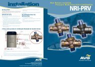
installation<br />
INSTRUCTIONS<br />
INSTALLATION<br />
The pressure reduction valve must be installed by a licensed plumber and<br />
in accordance with AS/NZS 3500, relevant local requirements and the<br />
following manufacturer’s instructions.<br />
IMPORTANT NOTE<br />
Flush out your lines to remove any debris or dirt particles that may cause<br />
the valve to malfunction.<br />
1. The pressure reduction valve may be installed horizontally or vertically.<br />
2. It is recommended that isolation valves be fitted either side of the<br />
pressure reduction valve to assist future maintenance operations.<br />
3. The <strong>NRI</strong>-<strong>PRV</strong>15 and <strong>NRI</strong>-<strong>PRV</strong>20 are protected by an internal stainless<br />
steel filter. If the valve is being installed in an environment where fine<br />
dirt particles are present it is recommended that a line strainer be fitted<br />
upstream of the valve.<br />
5. Install the valve with the arrow on the valve body pointing in the<br />
direction of flow.<br />
For best operation the inlet pressure should be at least 100 kPa higher than<br />
the outlet pressure.<br />
RECOMMENDATIONS FOR<br />
INSTALLATION<br />
1. Do NOT install <strong>NRI</strong>-<strong>PRV</strong>’s below ground.<br />
2. If the installation is at risk of water hammer, fit a water hammer<br />
arrestor.<br />
3. If the pressure setting is important for the protection of equip ment fit a<br />
pressure relief valve downstream of the valve.<br />
4. Ensure that the valve is installed in an accessible position for future<br />
maintenance operations.<br />
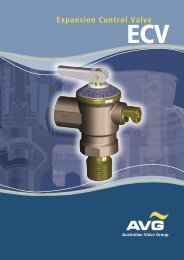
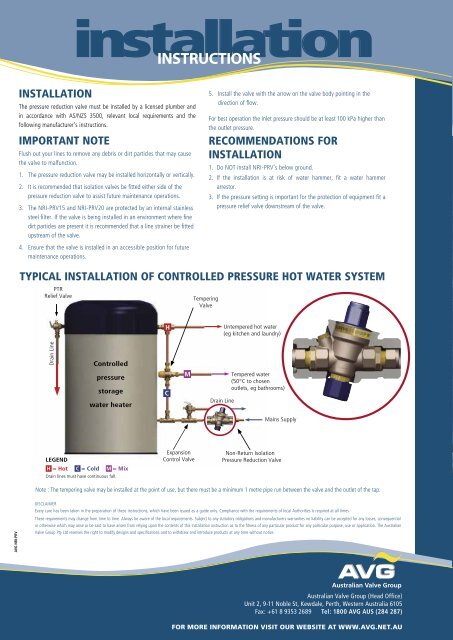
TYPICAL INSTALLATION OF CONTROLLED PRESSURE HOT WATER SYSTEM<br />
PTR<br />
Relief Valve<br />
Tempering<br />
Valve<br />
Untempered hot water<br />
(eg kitchen and laundry)<br />
Drain Line<br />
Controlled<br />
pressure<br />
storage<br />
water heater<br />
Drain Line<br />
Tempered water<br />
(50°C to chosen<br />
outlets, eg bathrooms)<br />
Mains Supply<br />
LEGEND<br />
= Hot = Cold = Mix<br />
Drain lines must have continuous fall.<br />
Expansion<br />
Control Valve<br />
Non-Return Isolation<br />
Pressure Reduction Valve<br />
Note : The tempering valve may be installed at the point of use, but there must be a minimum 1 metre pipe run between the valve and the outlet of the tap.<br />
AVG <strong>NRI</strong>-<strong>PRV</strong><br />
DISCLAIMER<br />
Every care has been taken in the preparation of these instructions, which have been issued as a guide only. Compliance with the requirements of local Authorities is required at all times.<br />
These requirements may change from time to time. Always be aware of the local requirements. Subject to any statutory obligations and manufacturers warranties no liability can be accepted for any losses, consequential<br />
or otherwise which may arise or be said to have arisen from relying upon the contents of this installation instruction as to the fitness of any particular product for any particular purpose, use or application. The Australian<br />
Valve Group Pty Ltd reserves the right to modify designs and speci fi cations and to withdraw and introduce products at any time without notice.<br />
Australian Valve Group (Head Office)<br />
Unit 2, 9-11 Noble St, Kewdale, Perth, Western Australia 6105<br />
Fax: +61 8 9353 2689 Tel: 1800 AVG AUS (284 287)<br />
FOR MORE INFORMATION VISIT OUR WEBSITE AT WWW.AVG.NET.AU