Effect of Neglecting Stator Transients in Doubly Fed Induction Generators Models
Effect of Neglecting Stator Transients in Doubly Fed Induction ...
Effect of Neglecting Stator Transients in Doubly Fed Induction ...

You also want an ePaper? Increase the reach of your titles
YUMPU automatically turns print PDFs into web optimized ePapers that Google loves.
1<br />
<strong>Effect</strong> <strong>of</strong> <strong>Neglect<strong>in</strong>g</strong> <strong>Stator</strong> <strong>Transients</strong> <strong>in</strong> <strong>Doubly</strong><br />
<strong>Fed</strong> <strong>Induction</strong> <strong>Generators</strong> <strong>Models</strong><br />
Pablo Ledesma, Member, IEEE, Julio Usaola, Member, IEEE,<br />
Universidad Carlos III de Madrid<br />
Butarque 15, 28911 Leganés, Madrid, Spa<strong>in</strong><br />
Abstract— This paper studies the effect <strong>of</strong> neglect<strong>in</strong>g stator<br />
transients <strong>in</strong> doubly fed <strong>in</strong>duction generators. The simulated<br />
cases <strong>in</strong>volve two extreme operation po<strong>in</strong>ts: one at subsynchronous<br />
speed, and one at supersynchronous speed. A shortcircuit<br />
fault is applied at the generator term<strong>in</strong>als. The evolution<br />
<strong>of</strong> different variables is exam<strong>in</strong>ed us<strong>in</strong>g two different models:<br />
one <strong>of</strong> them accounts for the stator transients and the other one<br />
neglects them.<br />
I. INTRODUCTION<br />
Neglection <strong>of</strong> the flux l<strong>in</strong>kage derivatives <strong>in</strong> the stator equations,<br />
is a common issue <strong>in</strong> transient stability studies <strong>in</strong>volv<strong>in</strong>g<br />
synchronous mach<strong>in</strong>es [1] and <strong>in</strong>duction mach<strong>in</strong>es [2] [3].<br />
Among the advantages <strong>of</strong> this simplification are a reduced<br />
order model, an easy <strong>in</strong>terface with the grid model, and longer<br />
<strong>in</strong>tegration steps.<br />
Nowadays, the <strong>in</strong>crease <strong>in</strong> the number <strong>of</strong> w<strong>in</strong>dmills with<br />
doubly fed <strong>in</strong>duction generators (DFIGs) <strong>in</strong> several power<br />
systems, has lead to the development <strong>of</strong> models <strong>of</strong> these<br />
generators which also neglect the stator electromagnetic transients<br />
[4].<br />
The simplification seems accurate when the DFIG works<br />
close to synchronous speed, because the rotor current frequency<br />
is close to zero and the DFIG operation po<strong>in</strong>t is similar<br />
to that <strong>of</strong> a synchronous generator. This paper studies the effect<br />
<strong>of</strong> neglect<strong>in</strong>g stator transients when the DFIG works at speeds<br />
which are different from the synchronous speed.<br />
II. SIMULATED CASES<br />
The simulated cases <strong>in</strong>volve two extreme operation po<strong>in</strong>ts:<br />
one at subsynchronous speed, where rotor speed is 90% <strong>of</strong><br />
the nom<strong>in</strong>al speed, and one at supersynchronous speed, where<br />
rotor speed is 110% <strong>of</strong> the nom<strong>in</strong>al speed.<br />
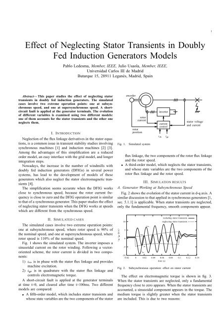
Fig. 1 shows the simulated system. The <strong>in</strong>verter imposes a<br />
s<strong>in</strong>usoidal current on the rotor w<strong>in</strong>d<strong>in</strong>g. Follow<strong>in</strong>g a vectororiented<br />
scheme, the rotor current is divided <strong>in</strong> two components:<br />
1) ¢¡¤£ is <strong>in</strong> phase with the stator flux l<strong>in</strong>kage and provides<br />
mach<strong>in</strong>e excitation.<br />
2) ¢¥¢£ is <strong>in</strong> quadrature with the stator flux l<strong>in</strong>kage and<br />
controls electromagnetic torque.<br />
A short-circuit fault is applied at the generator term<strong>in</strong>als<br />
at time t=0, and cleared after time t=100ms. Two different<br />
models are compared:<br />
¦ A fifth-order model, which <strong>in</strong>cludes stator transients and<br />
whose state variables are the two components <strong>of</strong> the stator<br />
Fig. 1.<br />
encoder<br />
rotor<br />
current<br />
rotor<br />
position<br />
Simulated system<br />
<strong>in</strong>verter<br />
current<br />
control<br />
§©¨§©©<br />
stator voltage<br />
and current<br />
flux l<strong>in</strong>kage, the two components <strong>of</strong> the rotor flux l<strong>in</strong>kage<br />
and the rotor speed.<br />
¦ A third-order model, which neglects the stator transients,<br />
and whose state variables are the two components <strong>of</strong> the<br />
rotor flux l<strong>in</strong>kage and the rotor speed.<br />
III. SIMULATION RESULTS<br />
A. Generator Work<strong>in</strong>g at Subsynchronous Speed<br />
Fig. 2 shows the evolution <strong>of</strong> the stator current <strong>in</strong> d-q axis. A<br />
similar discussion to that applied <strong>in</strong> synchronous generators [1,<br />
sec. 5.1.1] is applicable. When stator transients are neglected,<br />
only the fundamental frequency, smooth components appear.<br />
(p.u.)<br />
<br />
<br />
10<br />
5<br />
0<br />
-5<br />
Fig. 2.<br />
-10<br />
-0.02<br />
0<br />
<br />
<br />
<br />
0.02<br />
<br />
0.04<br />
0.06<br />
time (s)<br />
<strong>in</strong>clud<strong>in</strong>g stator transients<br />
neglect<strong>in</strong>g stator transients<br />
0.08<br />
0.1<br />
0.12<br />
Subsynchronous operation: effect on stator current<br />
The effect on electromagnetic torque is shown <strong>in</strong> fig. 3.<br />
When the stator transients are neglected, only a fundamental<br />
frequency close to zero appears. When the stator transients are<br />
accounted, a s<strong>in</strong>usoidal component appears <strong>in</strong> the torque. The<br />
medium torque is slightly greater when the stator transients<br />
are <strong>in</strong>cluded. This is due to two reasons:<br />
0.14
2<br />
electromagnetic torque (p.u.)<br />
1) The losses <strong>in</strong> the rotor resistance are greater due to the<br />
fundamental frequency currents <strong>in</strong>duced <strong>in</strong> the rotor.<br />
2) The first torque oscillation is positive.<br />
8<br />
6<br />
4<br />
2<br />
0<br />
-2<br />
-4<br />
<strong>in</strong>clud<strong>in</strong>g stator transients<br />
neglect<strong>in</strong>g stator transients<br />
rotor speed (p.u.)<br />
1.14<br />
1.135<br />
1.13<br />
1.125<br />
1.12<br />
1.115<br />
1.11<br />
1.105<br />
1.1<br />
<strong>in</strong>clud<strong>in</strong>g stator transients<br />
neglect<strong>in</strong>g stator transients<br />
1.095<br />
0 0.1 0.2 0.3 0.4 0.5 0.6<br />
time (s)<br />
Fig. 6. Supersynchronous operation: effect on rotor speed<br />
0.7<br />
-0.02<br />
0<br />
0.02<br />
0.04<br />
0.06<br />
time (s)<br />
0.08<br />
0.1<br />
0.12<br />
0.14<br />
1<br />
Fig. 3.<br />
Subsynchronous operation: effect on electromagnetic torque<br />
Both effects act <strong>in</strong> the sense <strong>of</strong> reduc<strong>in</strong>g rotor speed. As a<br />
result, speed <strong>in</strong>crease after the fault is slightly greater when<br />
the stator transients are neglected, as shown <strong>in</strong> fig. 4.<br />
rotor speed (p.u.)<br />
Fig. 4.<br />
0.92<br />
0.915<br />
0.91<br />
0.905<br />
0.9<br />
0.895<br />
0.89<br />
0.885<br />
0.88<br />
0<br />
0.1<br />
0.2<br />
time (s)<br />
<strong>in</strong>clud<strong>in</strong>g stator transients<br />
neglect<strong>in</strong>g stator transients<br />
Subsynchronous operation: effect on rotor speed<br />
Attend<strong>in</strong>g to stator voltage oscillations, and exclud<strong>in</strong>g the<br />
<strong>in</strong>itial oscillations due to the stator transients, the results are<br />
similar with both models, as shown <strong>in</strong> fig. 5<br />
0.3<br />
0.4<br />
0.5<br />
stator voltage (p.u.)<br />
0.8<br />
0.6<br />
0.4<br />
0.2<br />
Fig. 7.<br />
0<br />
0<br />
0.05<br />
0.1<br />
neglect<strong>in</strong>g stator transients<br />
0.15 0.2<br />
time (s)<br />
<strong>in</strong>clud<strong>in</strong>g stator transients<br />
0.25<br />
0.35<br />
Supersynchronous operation: effect on stator voltage<br />
IV. CONCLUSION<br />
The studied simulations show that the arguments applied to<br />
the effect <strong>of</strong> the stator transients on the synchronous generator<br />
model are also applicable to the DFIG model.<br />
<strong>Stator</strong> transients <strong>in</strong> the DFIG model are negligible because<br />
¦ The results are very similar from the transient stability<br />
po<strong>in</strong>t <strong>of</strong> view.<br />
Attend<strong>in</strong>g to the DFIG rotor speed, the results are more<br />
¦<br />
conservative.<br />
0.3<br />
0.4<br />
stator voltage (p.u.)<br />
1.2<br />
1<br />
0.8<br />
0.6<br />
0.4<br />
0.2<br />
Fig. 5.<br />
0<br />
0<br />
0.05<br />
0.1<br />
<strong>in</strong>clud<strong>in</strong>g stator transients<br />
neglect<strong>in</strong>g stator transients<br />
0.15 0.2<br />
time (s)<br />
0.25<br />
0.3<br />
0.35<br />
Subsynchronous operation: effect on stator voltage<br />
B. Generator Work<strong>in</strong>g at Supersynchronous Speed<br />
Figs. 6 and 7 show the evolution <strong>of</strong> rotor speed and<br />
stator voltage when the DFIG is operated at 110% <strong>of</strong> the<br />
synchronous speed. The same discussion applied to the subsynchronous<br />
operation is applicable to this case.<br />
0.4<br />
ACKNOWLEDGMENT<br />
The authors would like to thank José Román Wilhelmi<br />
for his help <strong>in</strong> search<strong>in</strong>g bibliography about the <strong>in</strong>duction<br />
mach<strong>in</strong>e.<br />
REFERENCES<br />
[1] P. Kundur, Power System Stability and Control. California: McGraw-<br />
Hill, 1994.<br />
[2] T. Skvaren<strong>in</strong>a and P. Krause, “Accuracy <strong>of</strong> a reduced order model <strong>of</strong><br />
<strong>in</strong>duction mach<strong>in</strong>es <strong>in</strong> dynamic stability studies,” IEEE Transactions<br />
on Power Apparatus and Systems, vol. PAS-98, no. 4, pp. 1192–1197,<br />
July/Aug 1979.<br />
[3] N. A. Khalil, O. T. Tan, and I. U. Baran, “Reduced order models for<br />
double-cage <strong>in</strong>duction motors,” IEEE Transactions on Power Apparatus<br />
and Systems, vol. PAS-101, no. 9, pp. 3135–3140, September 1982.<br />
[4] A. Feijóo, J. Cidrás, and C. Carrillo, “A third order model for the doublyfed<br />
<strong>in</strong>duction mach<strong>in</strong>e,” Electric Power Systems Research, vol. 56, pp.<br />
121–127, 2000.