BUSH
Operator's Manual 307 SERIES ROTARY CUTTERS - Caribe Turf
Operator's Manual 307 SERIES ROTARY CUTTERS - Caribe Turf
- No tags were found...

Create successful ePaper yourself
Turn your PDF publications into a flip-book with our unique Google optimized e-Paper software.
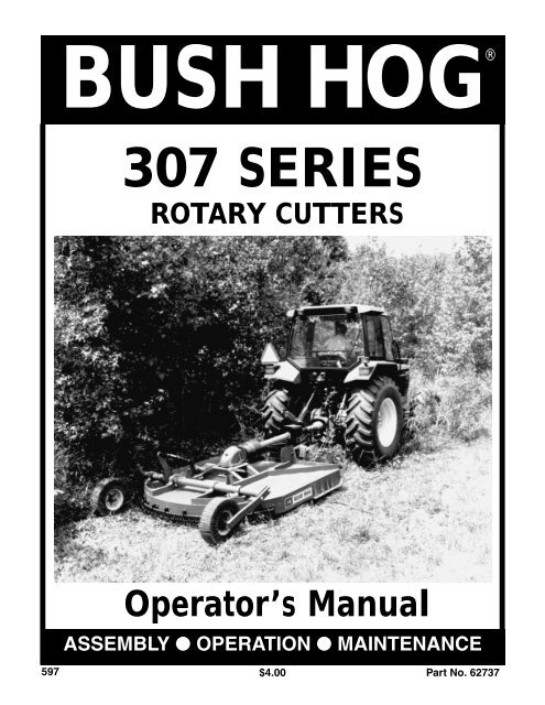
<strong>BUSH</strong> HOG®<br />
307 SERIES<br />
ROTARY CUTTERS<br />
Operator’s Manual<br />
ASSEMBLY ● OPERATION ● MAINTENANCE<br />
597 $4.00<br />
Part No. 62737
CONGRATULATIONS!<br />
You have invested in the best implement of its type on the market today.<br />
The care you give your Bush Hog implement will greatly determine your satisfaction<br />
with its performance and its service life. We urge a careful study of this manual to provide<br />
you with a thorough understanding of your new implement before operating, as well as<br />
suggestions for operation and maintenance.<br />
If your manual should become lost or destroyed, Bush Hog will be glad to provide you with<br />
a new copy. Order from Bush Hog, P. O. Box 1039, Selma, Alabama 36702-1039.<br />
As an authorized Bush Hog dealer, we stock genuine Bush Hog parts which are<br />
manufactured with the same precision and skill as our original equipment. Our trained<br />
service personnel are well informed on methods required to service Bush Hog equipment,<br />
and are ready and able to help you.<br />
Should you require additional information or assistance, please contact us.<br />
YOUR AUTHORIZED<br />
<strong>BUSH</strong> HOG DEALER<br />
BECAUSE <strong>BUSH</strong> HOG MAINTAINS AN ONGOING<br />
PROGRAM OF PRODUCT IMPROVEMENT, WE<br />
RESERVE THE RIGHT TO MAKE IMPROVEMENTS IN<br />
DESIGN OR CHANGES IN SPECIFICATIONS WITH-<br />
OUT INCURRING ANY OBLIGATION TO INSTALL<br />
THEM ON UNITS PREVIOUSLY SOLD.<br />
BECAUSE OF THE POSSIBILITY THAT SOME<br />
PHOTOGRAPHS IN THIS MANUAL WERE TAKEN OF<br />
PROTOTYPE MODELS, PRODUCTION MODELS MAY<br />
VARY IN SOME DETAIL. IN ADDITION, SOME<br />
PHOTOGRAPHS MAY SHOW SHIELDS REMOVED<br />
FOR PURPOSES OF CLARITY. NEVER OPERATE<br />
THIS IMPLEMENT WITHOUT ALL SHIELDS IN PLACE.
307 SERIES ROTARY CUTTERS<br />
TABLE OF CONTENTS<br />
SECTION/PARA<br />
PAGE<br />
Warranty.................................................2<br />
Dealer Preparation Check List ...............3<br />
Safety Precautions.................................4<br />
Federal Laws and Regulations...............5<br />
I. INTRODUCTION & DESCRIPTION ......6<br />
1-1 Introduction ......................................6<br />
1-2 Description.......................................6<br />
II. PREPARATION FOR USE .....................7<br />
2-1 Attaching To Tractor<br />
(3-Point Hitch Models) ......................7<br />
2-2 Attaching To Tractor<br />
(Pull Models) .....................................9<br />
III.OPERATING INSTRUCTIONS ..............9<br />
3-1 General Safety.................................9<br />
3-2 Adjusting for Work............................9<br />
3-2.1 Cutting Height Adjustment ............9<br />
3-3 Operation .......................................10<br />
3-4 Transporting...................................10<br />
IV.MAINTENANCE...................................10<br />
4-1 Maintenance Check List ................10<br />
SECTION/PARA<br />
PAGE<br />
4-2 Lubrication .....................................11<br />
4-3 Blade Holder Assembly<br />
Removal and Installation...............11<br />
4-4 Blade Replacement ......................11<br />
4-5 Slip Clutch Operational Check ......11<br />
4-6 Slip Clutch Adjustment..................12<br />
4-7 Gearbox Maintenance...................12<br />
4-8 Troubleshooting.............................13<br />
V. ASSEMBLY .........................................15<br />
5-1 Lift Models.....................................15<br />
5-2 Gearbox Input Shield ....................15<br />
5-3 Front and Rear Chain Guards.......16<br />
5-4 Front Guard...................................16<br />
5-5 Driveline Installation......................16<br />
5-6 Pull Type with Wheels to Side.......16<br />
5-7 Pull Type with Wheels to Rear ......17<br />
5-8 Offset Pull Type.............................17<br />
Safety Decals ......................................19<br />
Torque Specifications ..........................20<br />
RETAIL CUSTOMER’S RESPONSIBILITY<br />
UNDER THE <strong>BUSH</strong> HOG WARRANTY<br />
It is the Retail Customer and/or Operator’s responsibility to read the Operator’s Manual, to<br />
operate, lubricate, maintain and store the product in accordance with all instructions and<br />
safety procedures. Failure of the operator to read the Operator’s Manual is a misuse of this<br />
equipment.<br />
It is the Retail Customer and/or Operator’s responsibility to inspect the product and to have<br />
any part(s) repaired or replaced when continued operation would cause damage or excessive<br />
wear to other parts or cause a safety hazard.<br />
It is the Retail Customer’s responsibility to deliver the product to the authorized Bush Hog<br />
Dealer, from whom he purchased it, for service or replacement of defective parts which are<br />
covered by warranty. Repairs to be submitted for warranty consideration must be made within<br />
forty-five (45) days of failure.<br />
It is the Retail Customer’s responsibility for any cost incurred by the Dealer for traveling to or<br />
hauling of the product for the purpose of performing a warranty obligation or inspection.<br />
1
<strong>BUSH</strong> HOG ®<br />
LIMITED WARRANTY<br />
✯✯✯✯✯✯✯✯✯✯✯✯✯✯✯✯✯✯✯✯✯✯✯✯✯✯✯✯✯✯✯<br />
Bush Hog warrants to the original purchaser of any new Bush Hog equipment, purchased from an<br />
authorized Bush Hog dealer, that the equipment be free from defects in material and workmanship for a period<br />
of one (1) year for non-commercial, state, and municipalities’ use and ninety (90) days for commercial use from<br />
date of retail sale. The obligation of Bush Hog to the purchaser under this warranty is limited to the repair or<br />
replacement of defective parts.<br />
Replacement or repair parts installed in the equipment covered by this limited warranty are warranted<br />
for ninety (90) days from the date of purchase of such part or to the expiration of the applicable new equipment<br />
warranty period, whichever occurs later. Warranted parts shall be provided at no cost to the user at an<br />
authorized Bush Hog dealer during regular working hours. Bush Hog reserves the right to inspect any equipment<br />
or parts which are claimed to have been defective in material or workmanship.<br />
DISCLAIMER OF IMPLIED WARRANTIES & CONSEQUENTIAL DAMAGES<br />
Bush Hog’s obligation under this limited warranty, to the extent allowed by law, is in lieu of all warranties,<br />
implied or expressed, INCLUDING IMPLIED WARRANTIES OF MERCHANTABILITY AND FITNESS<br />
FOR A PARTICULAR PURPOSE and any liability for incidental and consequential damages with respect to<br />
the sale or use of the items warranted. Such incidental and consequential damages shall include but not be<br />
limited to: transportation charges other than normal freight charges; cost of installation other than cost<br />
approved by Bush Hog; duty; taxes; charges for normal service or adjustment; loss of crops or any other loss of<br />
income; rental of substitute equipment, expenses due to loss, damage, detention or delay in the delivery of<br />
equipment or parts resulting from acts beyond the control of Bush Hog.<br />
THIS LIMITED WARRANTY SHALL NOT APPLY:<br />
1. To vendor items which carry their own warranties, such as engines, tires, and tubes.<br />
2. If the unit has been subjected to misapplication, abuse, misuse, negligence, fire or other accident.<br />
3. If parts not made or supplied by Bush Hog have been used in connection with the unit, if, in the sole judgement<br />
of Bush Hog such use affects its performance, stability or reliability.<br />
4. If the unit has been altered or repaired outside of an authorized Bush Hog dealership in a manner<br />
which, in the sole judgement of Bush Hog, affects its performance, stability or reliability.<br />
5. To normal maintenance service and normal replacement items such as gearbox lubricant, hydraulic fluid,<br />
worn blades, or to normal deterioration of such things as belts and exterior finish due to use or<br />
exposure.<br />
6. To expendable or wear items such as teeth, chains, sprockets, belts, springs and any other items that in the<br />
company’s sole judgement is a wear item.<br />
NO EMPLOYEE OR REPRESENTATIVE OF <strong>BUSH</strong> HOG IS AUTHORIZED TO CHANGE THIS LIM-<br />
ITED WARRANTY IN ANY WAY OR GRANT ANY OTHER WARRANTY UNLESS SUCH CHANGE IS MADE<br />
IN WRITING AND SIGNED BY <strong>BUSH</strong> HOG’S SERVICE MANAGER, POST OFFICE BOX 1039, SELMA,<br />
ALABAMA 36702-1039.<br />
✯✯✯✯✯✯✯✯✯✯✯✯✯✯✯✯✯✯✯✯✯✯✯✯✯✯✯✯✯✯✯<br />
Record the model number, serial number and date<br />
purchased. This information will be helpful to your MODEL NUMBER<br />
dealer if parts or service are required.<br />
MAKE CERTAIN THE WARRANTY REGISTRATION<br />
CARD HAS BEEN FILED WITH <strong>BUSH</strong> HOG/<br />
SELMA, ALABAMA<br />
2<br />
SERIAL NUMBER<br />
DATE OF RETAIL SALE
DEALER PREPARATION CHECK LIST<br />
307 SERIES ROTARY CUTTERS<br />
BEFORE DELIVERING MACHINE — The following check list should be completed.<br />
Use the Operator’s Manual as a guide.<br />
❒ 1. Assembly completed.<br />
❒ 2. Gearbox filled with oil.<br />
❒ 3. All fittings lubricated.<br />
❒ 4. All shields in place and in good condition.<br />
❒ 5. All fasteners torqued to specifications given in Torque Chart.<br />
❒ 6. Slip clutches have been checked for proper operation.<br />
❒ 7. All decals in place and readable. (See decal page.)<br />
❒ 8. Overall condition good (i.e. paint, welds)<br />
❒ 9. Operators manual has been delivered to owner and he has been instructed<br />
on the safe and proper use of the cutter.<br />
❒ 10. Purchaser or dealer elects to delete deflectors. (front chains)<br />
Explanation:<br />
WARNING<br />
For Non-Agricultural use, OSHA, ASAE, SAE and ANSI standards require the use of<br />
Chain Guards or other protective guards at all times. Bush Hog strongly recommends<br />
the use of such guards for Agricultural uses as well, to reduce the risk of property<br />
damage, serious bodily injury or even death from objects thrown out by or from contact<br />
with the cutting blades.<br />
Dealer’s<br />
Signature<br />
Purchaser’s<br />
Signature<br />
THIS CHECKLIST TO REMAIN IN OWNER’S MANUAL<br />
It is the responsibility of the dealer to complete the procedures listed<br />
above before delivery of this implement to the customer.<br />
3
IMPORTANT SAFETY PRECAUTIONS<br />
This symbol is used to call attention to safety<br />
precautions that should be followed by<br />
the operator to avoid accidents. When you<br />
see this symbol, carefully read the message<br />
that follows and heed its advice. Failure to<br />
comply with safety precautions could result<br />
in serious bodily injury.<br />
In addition to the design and configuration of equipment, hazard control and accident prevention are dependent<br />
upon the awareness, concern, prudence and proper training of personnel in the operation, transport,<br />
maintenance and storage of equipment. Lack of attention to safety can result in accident, personal injury,<br />
reduction of efficiency and worst of all—loss of life. Watch for safety hazards and correct deficiencies promptly.<br />
Use the following safety precautions as a general guide to safe operations when using this machine.<br />
Additional safety precautions are used throughout this manual for specific operating and maintenance procedures.<br />
Read this manual and review the safety precautions often until you know the limitations.<br />
1. Read the Operator’s Manual. Failure to read the Operator’s Manual is considered a misuse of this<br />
equipment.<br />
2. Become familiar with all the machine’s controls and all the caution, warning and danger decals affixed<br />
to the machine before attempting to start or operate.<br />
3. Before starting or operating the machine, make a walk around inspection and check for obvious<br />
defects such as loose mounting bolts and damaged components. Correct any deficiency before<br />
starting.<br />
4. Do not allow children to operate the cutter. Do not allow adults to operate it without proper instruction.<br />
5. Do not carry passengers.<br />
6. Keep the area of operation clear of all persons, particularly small children and pets. The operator<br />
should cease mowing whenever anyone comes within the operating area.<br />
7. Clear the work area of objects which might be picked up and thrown.<br />
8. Use a piece of cardboard or wood rather than hands to search for hydraulic leaks. Escaping hydraulic<br />
oil under pressure can penetrate skin. If fluid is injected into the skin, it must be surgically removed<br />
within a few hours by a doctor familiar with this form of injury or gangrene may result.<br />
9. Do not operate without all guards and shields in place and in good condition.<br />
10. Lower implement to ground, stop tractor engine, apply parking brake, and allow blades to completely<br />
stop before leaving the tractor.<br />
11. Keep hands and feet away from blades.<br />
12. This cutter is not to be operated along highways or in any area where people may be present unless<br />
all sides of the unit are enclosed by permanent bands, safety chains or other factory approved safety<br />
shields that are in good repair.<br />
13. Wear personal protective equipment such as, but not limited to, protection for eyes, ears, feet, hands<br />
and head when operating or repairing the equipment. Do not wear loose clothing or jewelry that may<br />
catch on equipment moving parts.<br />
14. When performing adjustments or maintenance on the cutter, first lower it to the ground or block it<br />
securely at a workable height.<br />
15. Never stand between tractor and cutter while tractor is being backed to the cutter hitch.<br />
16. Reduce speed when transporting cutter to avoid bouncing and momentary loss of steering.<br />
17. Use tractor flashing warning lights, day or night, when transporting cutter on road or highways unless<br />
prohibited by law.<br />
18. In the event that someone other than yourself will operate this equipment we firmly suggest that all<br />
SAFETY references be discussed prior to operation.<br />
19. It is recommended that tractor be equipped with Rollover Protective System (ROPS) and seat belt be<br />
used in all mowing operations.<br />
4
IMPORTANT FEDERAL LAWS AND REGULATIONS* CONCERNING<br />
EMPLOYERS, EMPLOYEES AND OPERATIONS.<br />
*(This section is intended to explain in broad terms the concept and effect of the following federal laws and<br />
regulations. It is not intended as a legal interpretation of the laws and should not be considered as such).<br />
U.S. Public Law 91-596 (The Williams-Steiger Occupational and Health Act of 1970) OSHA<br />
This Act Seeks:<br />
“...to assure so far as possible every working man and woman in the nation safe and healthful working<br />
conditions and to preserve our human resources...”<br />
DUTIES<br />
Sec. 5 (a) Each employer—<br />
(1) shall furnish to each of his employees employment and a place of employment<br />
which are free from recognized hazards that are causing or are likely to cause<br />
death or serious physical harm to his employees;<br />
(2) shall comply with occupational safety and health standards promulgated under<br />
this Act.<br />
(b) Each employee shall comply with occupational safety and health standards<br />
and all rules, regulations and orders issued pursuant to this Act which are<br />
applicable to his own actions and conduct.<br />
OSHA Regulations<br />
Current OSHA regulations state in part: “At the time of initial assignment and at least annually thereafter, the<br />
employer shall instruct every employee in the safe operation and servicing of all equipment with which the<br />
employee is, or will be involved.” These will include (but are not limited to) instructions to:<br />
Keep all guards in place when the machine is in operation;<br />
Permit no riders on equipment;<br />
Stop engine, disconnect the power source, and wait for all machine movement to stop before<br />
servicing, adjusting, cleaning or unclogging the equipment, except where the machine must be<br />
running to be properly serviced or maintained, in which case the employer shall instruct employees<br />
as to all steps and procedures which are necessary to safely service or maintain the equipment.<br />
Make sure everyone is clear of machinery before starting the engine, engaging power, or operating<br />
the machine.<br />
EMPLOYEE TRACTOR OPERATING INSTRUCTIONS:<br />
1. Securely fasten your seat belt if the tractor has a<br />
ROPS.<br />
5. Watch where you are going, especially at row<br />
ends, on roads, and around trees.<br />
2. Where possible, avoid operating the tractor near<br />
ditches, embankments, and holes.<br />
3. Reduce speed when turning, crossing slopes, and<br />
on rough, slick, or muddy surfaces.<br />
4. Stay off slopes too steep for safe operation.<br />
6. Do not permit others to ride.<br />
7. Operate the tractor smoothly - no jerky turns,<br />
starts, or stops.<br />
8. Hitch only to the drawbar and hitch points recommended<br />
by tractor manufacturers.<br />
9. When tractor is stopped, set brakes securely and<br />
use park lock if available.<br />
Child Labor Under 16 Years Old<br />
Some regulations specify that no one under the age of 16 may operate power machinery. It is your<br />
responsibility to know what these regulations are in your own area or situation. (Refer to U.S. Dept. of<br />
Labor, Employment Standard Administration, Wage & Home Division, Child Labor Bulletin #102.)<br />
5
SECTION I<br />
INTRODUCTION AND DESCRIPTION<br />
1-1 INTRODUCTION<br />
We are pleased to have you as a Bush Hog customer.<br />
Your 307 Series Rotary Cutter has been<br />
carefully designed to give maximum service with<br />
minimum down time. This manual is provided to<br />
give you the necessary operating and maintenance<br />
instructions for keeping your rotary cutter in top<br />
operating condition. Please read this manual thoroughly.<br />
Understand what each control is for and<br />
how to use it. Observe all safety precautions<br />
decaled on the machine and noted throughout the<br />
manual for safe operation of implement. If any<br />
assistance or additional information is needed, contact<br />
your authorized Bush Hog dealer.<br />
1-2 DESCRIPTION<br />
The 307 Series rotary cutters (Figure 1-1) are<br />
designed for medium duty applications such as<br />
grass, corn stalks and light brush. These cutters are<br />
single spindle with two free-swinging blades. Freeswinging<br />
blades reduce the shock of impact when a<br />
stationary object is hit. Additional protection is provided<br />
by a slip clutch on the gearbox input shaft. A<br />
round blade holder allows the cutter to “ride over”<br />
stumps and similar immovable objects. Model 307<br />
cutters are attached to the tractor using 3-point Cat<br />
II or III standard or quick hitches or pull hitches.<br />
Standard equipment includes driveline shields,<br />
clutch shields and front discharge shields (deflectors).<br />
Figure 1-1 Major Components<br />
Driveline<br />
Support Yoke<br />
Chains<br />
Gearbox<br />
NOTE: Dealer or purchaser may elect to delete<br />
front and rear discharge shields (deflectors) at their<br />
option. Refer to “WARNING” in Section 3-3.<br />
NOTE<br />
All references made to right, left, front, rear, top or<br />
bottom are as viewed facing the direction of forward<br />
travel with implement properly attached to tractor.<br />
Table 1 Technical Specifications<br />
SERIES 307<br />
Cutting Width 84”<br />
Transport Width 107-1/2”<br />
Length<br />
137” Pull Type<br />
Hitch<br />
3-Point Cat II and Cat. III<br />
and Cat. II & III Quick Hitch or Pull Type<br />
Cutting Height 2” - 12”<br />
Cutting Capacity<br />
3” Diameter<br />
Driveshaft ASAE Category 4 or 5<br />
Gearbox<br />
540 RPM (125 HP)<br />
Blades<br />
1/2” x 4” Uplift<br />
Blade Tip Speed<br />
11,875 fpm<br />
Blade Holder<br />
Round<br />
Top Deck<br />
7 Ga. Steel<br />
Side Bands 1/4” x 8”<br />
Minimum Tractor HP<br />
60 (Lift), 40 (Pull)<br />
Front & Rear Deflectors Front chains are standard, rear chains are optional<br />
Wheels<br />
Laminated<br />
Approximate Weight (lbs.) 1701 lbs. 1<br />
Strongback<br />
1 - Weight includes deflector chains front and standard 3-point hitch. SPECIFICATIONS SUBJECT TO CHANGE WITHOUT NOTICE<br />
6<br />
3-Point Hitch with Flex Link<br />
Hitch Pin<br />
Skid<br />
Cutting Height<br />
Adjustment Ratchet<br />
Tailwheel<br />
Assembly<br />
Shock Absorber<br />
Assembly
2-1 ATTACHING TO TRACTOR<br />
(3-Point Hitch Models)<br />
WARNING<br />
NEVER STAND BETWEEN TRACTOR AND<br />
CUTTER WHILE TRACTOR IS BEING BACKED<br />
TO HITCH.<br />
WARNING<br />
ADDITIONAL TRACTOR FRONT BALLAST<br />
MAY BE NEEDED FOR STABLE OPERATION<br />
AND TRANSPORT OF THE 3-POINT HITCH<br />
MOUNTED CUTTER. SEE TRACTOR OPERA-<br />
TOR’S MANUAL FOR RECOMMENDED<br />
WEIGHTS.<br />
WARNING<br />
DO NOT USE PTO SHAFT ADAPTERS TO<br />
CHANGE SIZE OF TRACTOR PTO SHAFT.<br />
THE CORRECT DRIVELINE MUST BE USED<br />
TO MATCH TRACTOR PTO SHAFT.<br />
A. Arrange hitch pins, flexible link and bushings<br />
as shown in Figures 2-1 and 2-2 depending on your<br />
tractor and hitch type.<br />
B. Attach cutter to tractor 3-point hitch per tractor<br />
operator’s manual. Do not attach driveline at this time.<br />
C. Raise 3-point hitch until front of cutter is approximately<br />
1-2 inches (25-51mm) lower than rear for<br />
standard cut or until front of cutter is 1 inch (35mm)<br />
SECTION II<br />
PREPARATION FOR USE<br />
higher than rear for extra shredding. Shut down<br />
tractor. Securely block cutter in position. For further<br />
explanation of cutter adjustment, see paragraph 3-2.<br />
NOTE<br />
Due to the many variations in tractor / implement<br />
hitch points and corresponding differences<br />
in distances between tractor PTO<br />
shafts and implement input shafts, drivelines<br />
may need to be shortened as described in the<br />
following steps:<br />
D. Raise and lower cutter to determine position<br />
with shortest distance between the tractor PTO shaft<br />
and gearbox input shaft. Shut down tractor leaving<br />
cutter in position of shortest distance. Securely<br />
block cutter in position.<br />
E. Pull driveline apart. Attach outer (female) section<br />
to tractor PTO shaft. Pull on driveline section to<br />
be sure that yoke locks into place.<br />
F. Hold driveline sections parallel to each other to<br />
determine if too long. Each section should end<br />
approximately 3 inches (76mm) short of reaching<br />
universal joint shield on opposite section. If too<br />
long, measure 3 inches (76mm) back from universal<br />
joint shield and mark on opposite section. (Figure 2-<br />
3). Do this for both sections.<br />
G. Raise and lower cutter to determine position<br />
with greatest distance between PTO shaft and gearbox<br />
input shaft. Shut down tractor leaving cutter in<br />
position of greatest distance. Securely block cutter<br />
in position.<br />
Figure 2-1 Cat. II & III Heavy Duty Hitch<br />
Flexible Link<br />
Cat. III<br />
Cat. II<br />
Figure 2-2 Cat. II & III Heavy Duty Quick Hitch<br />
Cat. III Quick<br />
Hitch Position<br />
Cat. II, Cat. III<br />
Bushings<br />
Cat. II Position<br />
Cat. II Quick Hitch Position<br />
Cat. III Position<br />
Cat. II or III Quick Hitch Position<br />
7
Figure 2-3<br />
J. Using cut off section of shield as a guide, cut<br />
shaft the same amount. (Figure 2-6)<br />
Figure 2-6<br />
H. Hold driveline sections parallel to each other<br />
and check for minimum 6 inches (15cm) overlap.<br />
Figure 2-4). If driveline has been marked for cutting,<br />
overlap will be the distance between two marks. If<br />
driveline has less than minimum overlap, do not use.<br />
Contact authorized Bush Hog dealer.<br />
Figure 2-4<br />
Minimum Overlap<br />
K. Repeat steps “I” and “J” to other driveline<br />
section.<br />
L. Deburr ends of driveline sections and clean<br />
away all chips and filings. (Figure 2-7)<br />
Figure 2-7<br />
NOTE<br />
If driveline is the correct length, omit the following<br />
steps “I” through “L” and proceed to step “M”.<br />
I. Clamp driveline in a well padded vice to prevent<br />
damage to the shield. Cut off shield where<br />
marked. (Figure 2-5)<br />
Figure 2-5<br />
M. Apply multi-purpose grease to inside of outer<br />
(female) driveline section. Assemble driveline and<br />
install on tractor and cutter. Pull on each driveline<br />
section to be sure yokes lock into place. Make certain<br />
driveline shielding is in place and in good condition.<br />
N. Adjust lower lift arm(s) to level cutter right to left.<br />
Refer to tractor operator's manual for instructions.<br />
NOTE<br />
After attaching driveline to tractor, attach driveline<br />
shield chains from both ends of driveline shielding<br />
to stationary locations.<br />
8
2-2 ATTACHING TO TRACTOR<br />
(Pull Models)<br />
WARNING<br />
NEVER STAND BETWEEN TRACTOR<br />
AND CUTTER WHILE TRACTOR IS<br />
BEING BACKED TO HITCH<br />
A. Adjust tractor drawbar length to dimension<br />
shown in Figure 2-8. Incorrect drawbar length will<br />
change driveline operating angle causing possible<br />
damage.<br />
Figure 2-8 Tractor Drawbar Adjustment<br />
540 RPM PTO<br />
1-3/8” 6 SPLINE<br />
14 IN<br />
B. Connect cutter to tractor drawbar using a 7/8” diameter<br />
approved pin with linch pin retainer or equivalent.<br />
WARNING<br />
DO NOT USE PTO SHAFT ADAPTORS<br />
TO CHANGE SIZE OF TRACTOR PTO<br />
SHAFT. THE CORRECT DRIVELINE<br />
MUST BE USED TO MATCH TRACTOR<br />
PTO SHAFT.<br />
C. Connect driveline to tractor PTO shaft. Make certain<br />
quick disconnect pin is securely seated in PTO shaft<br />
groove. Make certain driveline shielding is in place and in<br />
good condition.<br />
D. Adjust pillow block bearing mount up or down as<br />
necessary to achieve the least amount of driveline angle.<br />
SECTION III<br />
OPERATING INSTRUCTIONS<br />
3-1 GENERAL SAFETY<br />
Only qualified people should operate this machine.<br />
Operator should wear hard hat, safety glasses and<br />
safety shoes. It is recommended that tractor be<br />
equipped with Rollover Protective Systems (ROPS)<br />
and a seat belt be used. Before beginning operation,<br />
clear work area of objects that may be picked<br />
up and thrown. Check for ditches, stumps, holes or<br />
other obstacles that could upset tractor or damage<br />
cutter. Always turn off tractor engine, set parking<br />
brake, and allow cutter blades to come to a complete<br />
stop before dismounting tractor.<br />
3-2 ADJUSTING FOR WORK<br />
The cutter should be operated at the highest position<br />
which will give desired cutting results. This will help<br />
prevent the blades from striking the ground, reducing<br />
blade wear and undue strain on the machine.<br />
For best results under heavier cutting conditions,<br />
always tilt the cutter approximately 2 inches (51mm)<br />
lower in the front. This tilt decreases horsepower<br />
requirements and increases potential ground speed.<br />
When fine shredding is desired, adjust cutter deck<br />
level or slightly lower in the rear. This will keep the<br />
foliage under cutter until thoroughly shredded. More<br />
power is required for shredding.<br />
WARNING<br />
THE CUTTER CAN FALL FROM HYDRAULIC<br />
SYSTEM FAILURE. TO AVOID SERIOUS<br />
INJURY OR DEATH, SECURELY SUPPORT<br />
CUTTER BEFORE WORKING UNDER-<br />
NEATH.<br />
WARNING<br />
AVOID PLACING HANDS, FEET OR ANY<br />
OTHER BODY PARTS BENEATH THE<br />
CUTTER WHILE MAKING HEIGHT<br />
ADJUSTMENTS.<br />
hydraulic cylinder on the cutter. 3-point lift models may<br />
be raised or lowered at the front by adjusting the tractor<br />
lift arms. Pull models may be raised or lowered at the<br />
front by adjusting the position of the tongue:<br />
A. Using ratchet, (or cylinder), adjust to desired cutting<br />
height.<br />
B. Securely block front of cutter in position.<br />
C. Loosen, but do not remove tongue pivot bolts.<br />
D.Remove tongue adjusting bolts. Pivot tongue into<br />
position giving desired tilt to cutter deck. (Figure 3-1)<br />
E. Reinstall adjusting bolts. Tighten pivot bolts.<br />
Figure 3-1 Tongue Adjustment<br />
3-2.1 CUTTING HEIGHT ADJUSTMENT<br />
The rear of the cuttert may be manually adjusted from 2”<br />
to 12” by adjusting the ratchet assembly up or<br />
down.(Figure 1-1) If equipped with the optional hydraulic<br />
system, the rear of the cutter may be raised or lowered<br />
by using the tractor’s hydraulic system connected to the<br />
Pivot Bolt<br />
Adjusting Bolt & Holes<br />
9
3-3 OPERATION<br />
A. Perform BEFORE EACH USE maintenance<br />
listed in paragraph 4-1.<br />
B. Start tractor.<br />
C. With tractor at idle speed, engage PTO drive.<br />
D. Adjust cutter to working position.<br />
DANGER<br />
STAY CLEAR OF ROTATING DRIVELINE. DO<br />
NOT OPERATE WITHOUT DRIVELINE<br />
SHIELDS IN PLACE AND IN GOOD CONDI-<br />
TION. FAILURE TO HEED THESE WARNINGS<br />
MAY RESULT IN PERSONAL INJURY OR<br />
DEATH.<br />
E. Set tractor throttle for appropriate PTO speed<br />
(540 RPM).<br />
DANGER<br />
ROTATING CUTTER BLADES. STAND<br />
CLEAR UNTIL ALL MOTION HAS STOPPED.<br />
TO AVOID AN ACCIDENTAL FALL FROM<br />
THE TRACTOR AND POSSIBLE INJURY BY<br />
THE MOWER, IT IS RECOMMENDED THAT<br />
THE TRACTOR BE EQUIPPED WITH ROPS<br />
(ROLLOVER PROTECTIVE SYSTEM) AND<br />
THAT A SEAT BELT BE USED BY THE OPER-<br />
ATOR FOR ALL MOWING OPERATIONS.<br />
F. Place tractor in gear and begin cutting. Tractor forward<br />
speed should be controlled by gear selection,<br />
4-1 MAINTENANCE CHECK LIST<br />
Perform scheduled maintenance as outlined below.<br />
Lower machine to ground, turn off tractor and set parking<br />
brake before doing maintenance inspections or work.<br />
Some checks may require raising machine off ground<br />
and supporting with blocks. All bolts should be torqued<br />
as recommended in the torque specifications chart<br />
unless otherwise indicated.<br />
WARNING<br />
THE CUTTER CAN FALL FROM HYDRAULIC<br />
SYSTEM FAILURE. TO AVOID SERIOUS<br />
INJURY OR DEATH, SECURELY SUPPORT<br />
CUTTER BEFORE WORKING UNDERNEATH.<br />
BEFORE EACH USE<br />
1. Check tractor tire air pressure. Refer to tractor<br />
operator’s manual.<br />
2. Check blades and spindle to be sure that no foreign<br />
objects such as wire or steel strapping bands<br />
are wrapped around them.<br />
3. Check blade bolts for tightness. Tighten to 450<br />
ft./lbs. (609 Nm).<br />
4. Inspect blades for wear. Replace if necessary per<br />
paragraph 4-4. Always replace both blades on<br />
SECTION IV<br />
MAINTENANCE<br />
10<br />
not engine speed. For maximum cutting efficiency, forward<br />
speed should allow cutter to maintain a constant,<br />
maximum blade speed. Do not exceed 5 mph (8kph). If<br />
PTO drive is disengaged due to cutter stalling or tractor<br />
engine bogging, cutter must be moved to a “cut” area and<br />
tractor throttle reduced to idle before re-engaging.<br />
Always cut up and down the face of slopes, never across.<br />
WARNING<br />
ALL ROTARY CUTTERS HAVE THE ABILITY<br />
TO DISCHARGE OBJECTS AT HIGH SPEEDS<br />
WHICH COULD RESULT IN SERIOUS INJURY<br />
TO BYSTANDERS OR PASSERS-BY.<br />
THEREFORE, THIS CUTTER IS NOT TO BE<br />
OPERATED ALONG HIGHWAYS OR IN ANY<br />
AREA WHERE PEOPLE MAY BE PRESENT<br />
UNLESS ALL SIDES OF THE UNIT ARE<br />
ENCLOSED BY PERMANENT BANDS, SAFE-<br />
TY CHAINS, OR OTHER FACTORY APPROV-<br />
ED SAFETY SHIELDS THAT ARE IN GOOD<br />
REPAIR. CEASE MOWING WHENEVER ANY-<br />
ONE COMES WITHIN THE OPERATING AREA.<br />
3-4 TRANSPORTING<br />
When implement is transported on road or highway, day<br />
or night, use tractor flashing warning lights unless prohibited<br />
by law. A slow moving vehicle (SMV) sign must be<br />
visible from the rear by approaching vehicles. Do not<br />
exceed 15 mph (24kph) when traveling. Fully raise<br />
implement before transporting.<br />
spindle with two blades equal in weight. Use<br />
only genuine Bush Hog replacement parts.<br />
5. Make certain driveline shields are in place and in<br />
good repair to minimize entanglement injuries to<br />
persons by rotating drivelines.<br />
6. Make certain deflector shields (chains, bands, etc.)<br />
are in good repair to minimize injuries to persons by<br />
the discharge of the high speed thrown objects.<br />
7. Inspect wheel(s) for wear, damage, or foreign<br />
objects.Repair or replace if necessary.<br />
8. Perform BEFORE EACH USE lubrication per paragraph<br />
4-2.<br />
9. During operation, listen for abnormal sounds which<br />
might indicate loose parts, damaged bearings or<br />
other damage.<br />
AFTER EACH USE<br />
1. Clean all debris from machine especially underside of<br />
deck and affixed safety decals. Replace any missing<br />
or illegible decals.<br />
2. Inspect cutter for worn or damaged components.<br />
Repair/replace before next use. Any replacement<br />
components installed during repair shall include the<br />
components current safety decals specified by the<br />
manufacturer to be affixed to the component.
4-2 LUBRICATION (Figure 4-1)<br />
NOTE<br />
The multi-purpose grease referenced in this section is an<br />
NLGI Grade 2 type grease.<br />
BEFORE EACH USE<br />
1. Driveline Universal Joints - Apply multi-purpose<br />
grease with grease gun.<br />
2. Wheel Bearings-Apply multi-purpose grease with<br />
grease gun.<br />
3. Wheel Pivots-Apply multi-purpose grease with grease<br />
gun.<br />
4. Driveline Guard-Apply 2-3 shots of multi-purpose<br />
grease with grease gun to plastic fitting.<br />
5. PTO Driveline - Disconnect PTO driveline, pull<br />
the two sections apart, apply thin coat of multipurpose<br />
grease to inside of outer (female) sec<br />
tion. Reassemble sections and install. Pull each<br />
section to be sure driveline and shields are<br />
securely connected. Make certain PTO shielding<br />
is in good condition.<br />
6. Gearbox - Add EP80W-90 gear oil as necessary<br />
to bring oil level to check plug on top of housing.<br />
Figure 4-1 B<br />
(5) Before Each Use<br />
(4) Before Each Use<br />
Figure 4-2<br />
Blade Nut<br />
Removal<br />
Figure 4-1 A Lubrication<br />
(6) Before Each Use<br />
(3) Before Each Use<br />
(2) Before Each Use<br />
1-11/16” Socket<br />
wrench of this size is not available.<br />
B. Strike the blade holder several times with a<br />
heavy hammer and retighten lower shaft nut. This<br />
should be repeated several times<br />
(1) Before Each Use<br />
To remove yoke shield:<br />
Turn slotted head 90° with<br />
screwdriver, remove turn screw<br />
and slide cover back.<br />
WARNING<br />
THE CUTTER CAN FALL FROM HYDRAULIC<br />
SYSTEM FAILURE. TO AVOID SERIOUS<br />
INJURY OR DEATH, SECURELY SUPPORT<br />
CUTTER BEFORE WORKING UNDERNEATH.<br />
4-3 BLADE HOLDER ASSEMBLY<br />
REMOVAL AND INSTALLATION<br />
A. Remove the lower shaft nut and lockwasher.<br />
B.Wearing heavy gloves, grasp blade holder and<br />
pull off tapered shaft. If stuck, align bolt with access<br />
hole in top of cutter deck. Using sledge hammer and<br />
a piece of pipe, strike blade bar. Rotate pan to the<br />
other blade bolt and strike blade bar. Repeat until<br />
blade holder comes off. Care should be taken not to<br />
damage blade bolt threads.<br />
REPLACEMENT<br />
A. Replace blade holder and tighten the lower<br />
shaft nut to 600 ft./lbs. The nut should be tightened<br />
with a wrench having a three foot handle, or<br />
a section of pipe over the wrench handle, if a<br />
11<br />
4-4 BLADE REPLACEMENT (Figure 4-2)<br />
It is not necessary to remove the complete blade<br />
holder assembly to replace the blades. Blade bolts<br />
are accessible through a hole in the top of the cutter<br />
deck. Always replace both blades on a spindle using<br />
two blades having the same weight. Use only genuine<br />
Bush Hog replacement parts.<br />
A. Raise cutter and securely block in position.<br />
B. Remove nuts from blade bolts using a 1-11/16”<br />
socket through the access hole in the deck.<br />
C. Inspect blade bolt shoulder for wear. Replace<br />
if necessary.<br />
D. Assemble new blades to blade holder using<br />
blade bolts, nuts and lockwashers. Tighten nuts to<br />
450 ft./lbs. Strike blade bolt head with heavy hammer<br />
to seat, then retighten.<br />
E. Check to be sure blades swing 360° freely.<br />
If blades will not swing freely, remove, locate<br />
problem, and repair. Operating cutter when<br />
blades will not swing freely will cause excessive<br />
vibration, damaging implement.<br />
4-5 SLIP CLUTCH OPERATIONAL CHECK<br />
After implement had been stored for 30 days or<br />
more, perform the following operational check:<br />
A. Loosen eight nuts retaining clutch springs 1/3<br />
turn or until spring can be turned with fingers.<br />
B. With tractor at idle speed, engage tractor PTO<br />
drive for 2-3 seconds. Clutch should slip without
turning blades. If clutch does not slip, contact your<br />
authorized Bush Hog dealer.<br />
C. Retighten nuts to within 1/64” of original position.<br />
Initial spring length is shown in Figure 4-3.<br />
WARNING<br />
OVERTIGHTENING SPRING NUTS MAY<br />
CAUSE DAMAGE TO IMPLEMENT AND/OR<br />
TRACTOR DUE TO INCORRECT SLIP CLUTCH<br />
TORQUE SETTING. ALWAYS FOLLOW THE<br />
PROPER ADJUSTMENT PROCEDURE.<br />
4-6 SLIP CLUTCH ADJUSTMENT<br />
The slip clutch is factory preset to the correct torque<br />
for protecting implement and tractor. Periodic<br />
adjustment is recommended; refer to section 4-5.<br />
Should adjustment be needed, first check to be sure<br />
all spring lengths are the same. Initial spring length<br />
is shown in Figure 4-3. If necessary, adjust nut on<br />
any spring that is unequal. Adjust all eight spring<br />
retaining nuts 1/3 of a turn (2 flats on a nut) and<br />
check clutch slippage. If further adjustment is necessary,<br />
do so in 1/3 turn increments. Adjust only to<br />
provide sufficient torque to prevent slippage under<br />
normal conditions. Occasional slippage is normal<br />
for drivetrain protection. If satisfactory results cannot<br />
be obtained, consult your Bush Hog dealer.<br />
SEAL REPLACEMENT - To replace the seals on<br />
your cutter, follow the steps outlined below:<br />
1. Remove the blade holder and universal joint.<br />
2. Knock out old seals.<br />
3. Install new seals.<br />
BEARING ADJUSTMENT - Loose bearings can be<br />
detected by applying pressure in an “in and out”<br />
direction on the upper and lower shafts to check for<br />
end play. To tighten the bearings, the following procedure<br />
may be used.:<br />
1. Remove upper end housing. This provides<br />
access to both adjusting nuts.<br />
2. If your gearbox is an earlier model with a lockwasher<br />
and a grooved adjusting nut, the lock must<br />
be bent out of the groove of the adjusting nut before<br />
adjustments can be made.<br />
3. Tighten the adjusting nuts until slack is taken<br />
up. IMPORTANT: The gears are pressed on, and<br />
this could cause the adjusting nut to appear tight<br />
when there is still slackness in the bearings.<br />
Figure 4-4 Gearbox Internal Components<br />
IMPORTANT<br />
Do not overtighten nut and cause spring to<br />
become solid as this will cause shaft to fail.<br />
Figure 4-3 Spring Length<br />
With T80 on Shield 1-17/64”<br />
32.2 mm<br />
See<br />
Chart<br />
Seal<br />
With T60 on Shield 1-5/16”<br />
33.6 mm<br />
Adjusting Nuts<br />
4-7 GEARBOX MAINTENANCE (Figure 4-4)<br />
OIL LEVEL - The gearbox assembly on the 307<br />
rotary cutters are shipped from the factory less<br />
oil. Use EP80-90 gear oil and fill to the plug located<br />
on the top of the gearbox. Never fill the gear- box<br />
above this level. Seals could become damaged<br />
due to expansion.<br />
OIL SEAL LEAKAGE - The three main causes of oil<br />
seal failure are as follows:<br />
1. Operating cutter for any length of time with<br />
wire or litter wrapped around the upper or lower<br />
shaft.<br />
2. Loose bearings.<br />
3.Worn seals. Leaky seals should be replaced as<br />
soon as possible.<br />
Seal<br />
12
Figure 4-5 Tightening Bearings<br />
Old nut being split for removal<br />
Roll pin being driven in<br />
after tightening bearing<br />
4-8 TROUBLESHOOTING<br />
PROBLEM PROBABLE CAUSE REMEDY<br />
Uneven Cut Cutter not level side to side. See SECTION II<br />
Worn or bent blades. Replace blades per paragraph 4-4.<br />
Stripping or Windrowing Possible build-up of material under Clean cutter.<br />
cutter.<br />
Cutter not level.<br />
Refer to Section II.<br />
Worn blades. Replace per paragraph 4-4.<br />
Noisy Cutter Loose components. Check al bolts for tightness per<br />
paragraph 20.<br />
Low oil in gearboxes.<br />
Check for proper oil level. Refer to<br />
paragraph 4-2.<br />
Rapid Blade Wear Blade contacting the ground. Adjust cutter to operate at a height<br />
(Cutting Edge)<br />
that will eliminate ground contact.<br />
Rapid Blade Wear Cutter not being operated at Reduce ground speed.<br />
(Bolt Hole) rated RPM speed. Set tractor throttle for proper PTO<br />
speed.<br />
Too much ground speed.<br />
Use lower gear.<br />
Poor Shredding Job Incorrect deck tilt. Adjust per paragraph 3-2.<br />
Excessive ground speed. Reduce ground speed.<br />
Worn blades. Replace blades per paragraph 4-4.<br />
Cutter Vibration Cutter not being operated at rated Set tractor throttle for proper PTO<br />
RPM speed.<br />
speed.<br />
Possible build up of material on Clean blade pan.<br />
blade pan.<br />
Broken blade. Replace blades per paragraph 4-4.<br />
Blades unequal weight. Replace blades per paragraph 4-4.<br />
13
PRE-ASSEMBLY<br />
SAFETY PRECAUTIONS<br />
CAUTION<br />
THE FOLLOWING SAFETY PRECAUTIONS SHOULD BE THOROUGHLY UNDERSTOOD BEFORE<br />
ATTEMPTING MACHINE ASSEMBLY.<br />
1. Wear personal protective equipment such as, but not limited to protection for eyes, ears, feet, hands, lungs and<br />
head when assembling the equipment. Do not wear loose clothing or jewelry that may catch on equipment<br />
moving parts.<br />
2. Do not lift heavy parts or assemblies. Use crane, jack, tackle, fork trucks or other mechanical devices.<br />
3. Select an area for assembly that is clean and free of any debris which might cause persons working on<br />
the assembly to trip.<br />
4. Arrange parts to be assembled neatly in the work area and have tools or other mechanical assisting<br />
devices in easy reach.<br />
5. Inspect all parts and assemblies thoroughly and remove any sharp edges, grease, oil or dirt which might<br />
cause pieces to slip when handling.<br />
6. Preview the assembly instructions in your operator’s manual before proceeding further.<br />
7. If the assembly instructions call for parts or assemblies to be blocked up, use only blocking material that is<br />
in good condition and is capable of handling the weight of the assembly to be blocked. Also, insure that<br />
the blocking material is on a clean, dry surface.<br />
8. Never put hands or any other part of body under blocked up assemblies if at all possible.<br />
9. Always wear goggles or safety glasses when hammering, grinding, or drilling metal parts.<br />
10. If the assembly calls for welding or cutting, be sure that there are no flammable materials close at hand<br />
and that bystanders have taken necessary precautions.<br />
AFTER COMPLETING ANY ASSEMBLY STEP, THOROUGHLY READ THE NEXT STEP IN THE ASSEMBLY<br />
INSTRUCTIONS BEFORE PROCEEDING WITH THAT STEP.<br />
11. After completing assembly, thoroughly inspect the machine to be sure that all nuts, bolts, hydraulic fittings<br />
or any other fastened assemblies have been thoroughly tightened.<br />
12. After completing assembly, be sure that all safety locking devices or guards are in place.<br />
13. Before operating the machine, thoroughly read the operation section of this manual.<br />
14. Before operating, read the maintenance section of this manual to be sure that any parts requiring lubrication<br />
have been properly lubricated.<br />
BEFORE OPERATING THE EQUIPMENT, IF YOU HAVE ANY QUESTIONS REGARDING THE PROPER<br />
ASSEMBLY OR OPERATION, CONTACT YOUR AUTHORIZED <strong>BUSH</strong> HOG DEALER OR REPRESENTATIVE.<br />
14
Figure 5-1<br />
3-Point Hitch A-Frame<br />
SECTION V<br />
ASSEMBLY<br />
Gearbox Input Shield<br />
Yoke Assembly<br />
Metal Shield Bracket<br />
Flexible<br />
Link<br />
Axle Assembly<br />
Roll Pin & Collar<br />
Caster Arm<br />
Lower Hitch Pin<br />
Front Chain Guards<br />
Caster Wheel Assembly<br />
Rear Chain Guards<br />
Shock Absorber<br />
Ratchet Assembly<br />
5-1 ASSEMBLY - LIFT MODEL (Figure 5-1)<br />
IMPORTANT<br />
Tighten all fasteners to specifications on Torque<br />
Chart unless otherwise indicated.<br />
A. Remove lower bolts from hitch assembly. Place<br />
the hitch between struts on cutter deck and fasten in<br />
place with the bolts that were removed. Remove the<br />
bolt from the top of the A-frame.<br />
B. Bolt the yoke assembly from the top of the A-<br />
frame to the struts toward the rear of the strongbacks.<br />
C. Remove the bolts from the mounting plates on<br />
each end of the axle. Bolt caster arms to the axle<br />
using the bolts previously removed. The caster arms<br />
should be offset to the inside with the large washer on<br />
the bottom side.<br />
D. Remove the roll pins and collars from the caster<br />
wheel assemblies. Install the caster wheel pivot<br />
shafts up through the tubing on the ends of the caster<br />
arms. Replace the collars and roll pins on the pivot<br />
shafts.<br />
SHOCK ABSORBER<br />
E. First disassemble the shock absorber.Place<br />
short bolt on the inside of the frame and through hole<br />
1. Slide the long bolt through the shock absorber<br />
frame and hole 2, on the main frame, so that the<br />
frame will stay in alignment while tightening the short<br />
bolt. (Figure 5-6)<br />
F. Place spring and pad back on spring boss<br />
15<br />
(which is welded to shock absorber frame).<br />
G .Slide long bolt out and install bushing and rocker<br />
arm inside frame. Replace long bolt and tighten it<br />
securely.<br />
H. Install the ratchet assembly by connecting one<br />
end to the axle arm bracket and the other end to the<br />
rocker arm of the shock absorber assembly.<br />
I. Hydraulic Cylinder (Optional)- Install the cylinder<br />
between the axle arm bracket and the rocker arm of<br />
the shock absorber assembly. Plumb as shown in<br />
Figure 5-2.<br />
Figure 5-2 Cylinder Plumbing Diagram<br />
Breather Plug Hose<br />
Elbow<br />
Hydraulic Cylinder<br />
5-2 GEARBOX INPUT SHIELD<br />
9/16” JIC to 3/4” SAE ORB<br />
or 9/16” JIC to 1/2” NPT<br />
Remove four existing bolts from around input<br />
shaft in front of gearbox. Fasten metal shield bracket<br />
to gearbox using these bolts. Fasten plastic shield<br />
(with access opening to the top) to the shield bracket<br />
using four 5/16 x 3/4” bolts, flatwashers, lockwashers<br />
and nuts.
5-3 FRONT CHAIN GUARDS (Standard) &<br />
REAR CHAIN GUARDS (Optional)<br />
Position chain assemblies against mainframe as<br />
shown and fasten with 1/2 x 1-1/2” bolts, flatwashers,<br />
lockwashers and nuts. (Figure 5-1)<br />
5-4 FRONT GUARD ASSEMBLY (Optional)<br />
Fasten guard to center front of mainframe<br />
using1/2 x 1-1/2” bolts, flatwashers, lockwashers and<br />
nuts.<br />
Figure 5-2 Front Guard<br />
5-5 DRIVELINE INSTALLATION<br />
A. Remove pivot bolt from spline end of clutch.<br />
Remove inspection cover from clutch shield.<br />
B. Slide clutch onto gearbox input shaft aligning<br />
bolt holes with slot in input shaft. Fasten with clamp<br />
bolts, lockwashers and nuts. Torque to 30 ft./lbs.<br />
C. Loosen eight nuts retaining clutch springs<br />
1/3 turn or until spring can be turned with fingers.<br />
D. With tractor at idle speed, engage tractor PTO<br />
drive 2-3 seconds. Clutch should slip without<br />
turning blades.<br />
E. Retighten nuts to original position. If adjustment<br />
is necessary, refer to Section 4-6.<br />
WARNING<br />
OVER-TIGHTENING SPRING NUTS MAY<br />
CAUSE DAMAGE TO IMPLEMENT AND/OR<br />
TRACTOR DUE TO INCORRECT SLIP<br />
CLUTCH TORQUE SETTING. ALWAYS<br />
FOLLOW THE PROPER ADJUSTMENT PRO-<br />
CEDURE.<br />
IMPORTANT<br />
Before operation,fill gearbox with EP80W-90 gear<br />
oil to check plug on rear of gearbox. Allow time<br />
for oil to seep through bearings into lower housing,<br />
then recheck oil level. Insure that vent hole<br />
in fill plug is open to allow pressure to escape<br />
from gearbox during operation.<br />
5-6 ASSEMBLY - PULL TYPE WITH<br />
WHEELS POSITIONED ON THE SIDE<br />
A. Remove bolts from tongue assembly. Place<br />
tongue between struts on cutter deck and fasten using<br />
the bolts previously removed. (Figure 3-1)<br />
B. Remove the bolts from the mounting plates on<br />
each end of the axle. Bolt axle arms and hub assemblies<br />
to the axle using the bolts previously removed.<br />
The axle arms should offset outward, away from the<br />
cutter, and point toward the front.<br />
SHOCK ABSORBER<br />
C. First disassemble the shock absorber. Place<br />
short bolt and long bolt in the proper holes for automotive<br />
or solid tires. (Figures 5-7 or 5-8)<br />
D. Slide shock absorber frame into position and<br />
tighten the short bolt securely.<br />
E. Remove the long bolt and install spring and pad<br />
on spring boss. Install the rocker arm and bushing<br />
inside the shock absorber frame.<br />
F. Replace the long bolt through the rocker arm<br />
bushing and shock absorber frame, and tighten<br />
securely.<br />
G. Install the ratchet assembly by connecting one<br />
end to the axle ram bracket and the other end tto the<br />
rocker arm of the shock absorber assembly.<br />
H. To install the wheels, the cutter will have to be<br />
jacked up or lifted high enough for the wheels to clear<br />
the ground.<br />
WARNING<br />
RAISE THE CUTTER AND SECURELY<br />
BLOCK IT UP AT A HEIGHT THAT WILL<br />
ALLOW HANDS UNDER THE DECK.<br />
NOTE: When installing solid tires, turn the flat side of<br />
the lug nuts against the rim and tighten securely.<br />
JACKSHAFT & PILLOW BLOCK STAND<br />
I. Install the pillow block clamp bracket in the<br />
tongue as shown using 5/8 x 1-3/4” bolts, flatwashers,<br />
lockwashers and nuts. Install the stand between the<br />
lugs of the clamp bracket using the 5/8 x 3-3/4” bolt,<br />
lockwasher and nut. Note: Final positioning of the<br />
stand will be made after cutter is connected to tractor.<br />
The stand should be positioned so that driveline will<br />
be as straight as possible between the gearbox and<br />
the tractor PTO. Place the mounting bracket for the<br />
pillow block shield under the pillow block bearing and<br />
fasten them to the stand using 1/2 x 2” bolts, lockwashers<br />
and nuts. (Figure 5-4)<br />
J. Install the splined end of the jackshaft through<br />
the pillow block bearing and attach the slip clutch end<br />
to the gearbox input shaft. Tighten the lock collar set<br />
screw next to the bearing.<br />
K. Place shield over the pillow block and fasten<br />
with 1/4 x 3/4” bolts and locknuts.<br />
L After you have connected the cutter to the tractor,<br />
the driveline should be connected from the splined<br />
end of the jackshaft to the tractor PTO shaft.<br />
16
Figure 5-3 Pull Type With Wheels To The Rear<br />
Figure 5-4 Pillow Block Stand<br />
5-7 ASSEMBLY - PULL TYPE WITH<br />
WHEELS POSITIONED TO THE REAR<br />
NOTE:<br />
Assembly of the gearbox input shield,<br />
chain guards, front guard, driveline<br />
installation,and optional hydraulic cylinder<br />
is the same as for the lift models.<br />
Please refer back to those sections.<br />
Shield<br />
Bearing<br />
Jackshaft<br />
Clamp Bracket<br />
A. Remove bolts from tongue assembly. Place<br />
tongue between struts on cutter deck and fasten using<br />
the bolts previously removed. (Figure 3-1)<br />
B. Remove the bolts from the mounting plates on<br />
each end of the axle. Bolt axle arms and hub assemblies<br />
to the axle using the bolts previously removed.<br />
The axle arms should offset intward, toward the center<br />
of the cutter, and point toward the rear.<br />
SHOCK ABSORBER<br />
C. First disassemble the shock absorber. Place<br />
short bolt and long bolt in the proper holes as shown<br />
in Figure 5-9.<br />
D. Slide shock absorber frame into position and<br />
tighten the short bolt securely.<br />
E. Remove the long bolt and install spring and pad<br />
on spring boss. Install the rocker arm and bushing<br />
inside the shock absorber frame.<br />
F. Replace the long bolt through the rocker arm<br />
bushing and shock absorber frame, and tighten<br />
securely.<br />
G. Install the ratchet assembly by connecting one<br />
end to the axle ram bracket and the other end to the<br />
rocker arm of the shock absorber assembly.<br />
H. To install the wheels, the cutter will have to be<br />
jacked up or lifted high enough for the wheels to clear<br />
the ground.<br />
JACKSHAFT & PILLOW BLOCK STAND<br />
Refer back to Section 5-8, I. through L.<br />
Shield Bracket<br />
Bearing Stand<br />
5-8 ASSEMBLY - OFFSET PULL TYPE<br />
NOTE:<br />
Assembly of the offset models is the<br />
same as for the center pull models except<br />
for the tongue placement and the pillow<br />
block assembly.<br />
The Pillow block bar weldment fastens between<br />
the tongue mounting lugs on the cutter deck utilizing<br />
the top , forward holes. Fasten with 7/8 x 2” bolts, lockwashers<br />
and nuts. (Figure 5-5)<br />
Figure 5-5 Offset Pull Type Model 307<br />
Pillow Block Bar Weldment<br />
17
Figure 5-6<br />
Arrangement For Lift Type Cutters<br />
Short Bolt (Hole ➊)<br />
SHOCK ABSORBER ASSEMBLY<br />
➊ ➋ ➌ ➍ ➎ ➏<br />
Rocker Arm<br />
Rocker Arm Bushing<br />
Long Bolt (Hole ➋)<br />
Spring & Pad<br />
Shock Absorber Frame<br />
Figure 5-7 Pull Type, Auto Tires At Side<br />
NOTICE<br />
Proper installation of the shock absorber is<br />
required for efficient operation of the cutter.<br />
Locate the drawing or photograph of your<br />
type of cutter. Carefully lay out parts and<br />
insure that the proper bolts and holes align.<br />
Follow assembly instructions for your type<br />
cutter.<br />
Rocker Arm Long Bolt ➋ ➌ Short Bolt Spring & Pad<br />
Rocker Arm Bushing<br />
Shock Absorber Frame<br />
Figure 5-8 Pull Type, Solid Tires At Side<br />
Figure 5-9 Pull Type, Tires To The Rear<br />
Rocker Arm Long Bolt ➊ ➋ Short Bolt Spring & Pad Shock Absorber Frame Short Bolt ➍➎ Long Bolt<br />
Rocker Arm Bushing Shock Absorber Frame Spring & Pad Rocker Arm Bushing Rocker Arm<br />
18
SAFETY DECALS<br />
To promote safe operation, Bush Hog supplies safety decals on all products manufactured. Because damage<br />
can occur to safety decals either through shipment, use or reconditioning, Bush Hog will, upon request, provide<br />
safety decals for any of our products in the field at no charge. Contact your authorized Bush Hog dealer for<br />
more information.<br />
WARNING<br />
TO AVOID SERIOUS INJURY OR DEATH:<br />
¥ READ OPERATOR’S MANUAL BEFORE OPERATING AND<br />
FOLLOW ALL PRECAUTIONS.<br />
(CONTACT DEALER FOR MANUAL)<br />
¥ KEEP SHIELDS AND GUARDS IN PLACE. KEEP CLEAR<br />
OF DRIVES AND BELTS.<br />
¥ LOWER IMPLEMENT, STOP ENGINE AND PTO, ALLOW ALL<br />
MOVING PARTS TO STOP, AND REMOVE KEY BEFORE<br />
DISMOUNTING FROM TRACTOR.<br />
¥ KNOW HOW TO STOP TRACTOR AND EQUIPMENT<br />
QUICKLY IN AN EMERGENCY.<br />
¥ ALLOW NO CHILDREN OR UNQUALIFIED PERSONS TO<br />
OPERATE EQUIPMENT.<br />
¥ BE CAREFUL ON UNEVEN TERRAIN. DECREASE SPEED<br />
WHEN TURNING.<br />
¥ DO NOT OPERATE MOWER IN TRANSPORT POSITION.<br />
WARNING<br />
IMPLEMENT CAN FALL FROM HYDRAULIC<br />
SYSTEM RELEASE. TO AVOID SERIOUS<br />
INJURY OR DEATH:<br />
¥SHUT OFF TRACTOR ENGINE, REMOVE KEY, SECURE<br />
TRACTOR PARKING BRAKE AND BLOCK UP OR SECURELY<br />
SUPPORT IMPLEMENT BEFORE WORKING UNDERNEATH.<br />
¥PURGE ALL AIR FROM HYDRAULIC SYSTEM BEFORE<br />
ATTEMPTING TO RAISE OR LOWER THIS IMPLEMENT.<br />
¥STAND CLEAR IF LOWERING OR RAISING IMPLEMENT.<br />
¥DO NOT USE HAND OR SKIN TO CHECK FOR HYDRAULIC<br />
LEAKS. USE CARDBOARD OR WOOD.<br />
¥HIGH PRESSURE OIL LEAKS CAN PENETRATE SKIN<br />
CAUSING SERIOUS INJURY AND GANGRENE. CONSULT A<br />
PHYSICIAN IMMEDIATELY.<br />
¥ LOWER THE IMPLEMENT AND RELEASE HYDRAULIC<br />
PRESSURE BEFORE LOOSENING FITTINGS.<br />
¥REFER TO OWNER’S MANUAL FOR DETAILS.<br />
50029419<br />
50029419<br />
50029417<br />
78608<br />
78786<br />
19
Wrench<br />
Size “A”<br />
AMERICAN<br />
Bolt Head Markings<br />
SAE Grade 2<br />
(No Dashes)<br />
SAE Grade 5<br />
(3 Dashes)<br />
TORQUE SPECIFICATIONS<br />
Proper toque for American fasteners used on Bush Hog equipment.<br />
Recommended Torque in Foot Pounds (Newton Meters).*<br />
Bolt<br />
Diameter “B”<br />
SAE Grade 8<br />
(6 Dashes)<br />
BOLT DIAMETER<br />
WRENCH (IN.) “B” AND SAE SAE SAE<br />
SIZE (IN.) “A” THREAD SIZE GRADE 2 GRADE 5 GRADE 8<br />
7/16 1/4 - 2O UNC 6 (7) 8 (11) 12 (16)<br />
7/16 1/4 - 28 UNF 6 (8) 10 (13) 14 (18)<br />
1/2 5/16 - 18 UNC 11 (15) 17 (23) 25 (33)<br />
1/2 5/16 - 24 UNF 13 (17) 19 (26) 27 (37)<br />
9/16 3/8 - 16 UNC 20 (27) 31 (42) 44 (60)<br />
9/16 3/8 - 24 UNF 23 (31) 35 (47) 49 (66)<br />
5/8 7/16 - 14 UNC 32 (43) 49 (66) 70 (95)<br />
5/8 7/16 - 20 UNF 36 (49) 55 (75) 78 (106)<br />
3/4 1/2 - 13 UNC 49 (66) 76 (103) 106 (144)<br />
3/4 1/2 - 20 UNF 55 (75) 85 (115) 120 (163)<br />
7/8 9/16 - 12 UNC 70 (95) 109 (148) 153 (207)<br />
7/8 9/16 - 18 UNF 79 (107) 122 (165) 172 (233)<br />
15/16 5/8 - 11 UNC 97 (131) 150 (203) 212 (287)<br />
15/16 5/8 - 18 UNF 110 (149) 170 (230) 240 (325)<br />
1-1/8 3/4 - 10 UNC 144 (195) 266 (360) 376 (509)<br />
1-1/8 3/4 - 16 UNF 192 (260) 297 (402) 420 (569)<br />
1-5/16 7/8 - 9 UNC 166 (225) 430 (583) 606 (821)<br />
1-5/16 7/8 - 14 UNF 184 (249) 474 (642) 668 (905)<br />
1-1/2 1 - 8 UNC 250 (339) 644 (873) 909 (1232)<br />
1-1/2 1 - 12 UNF 274 (371) 705 (955) 995 (1348)<br />
1-1/2 1 - 14 UNF 280 (379) 721 (977) 1019 (1381)<br />
1-11/16 1-1/8 - 7 UNC 354 (480) 795 (1077) 1288(1745)<br />
1-11/16 1-1/8 - 12 UNF 397 (538) 890 (1206) 1444 (1957)<br />
1-7/8 1-1/4 - 7 UNC 500 (678) 1120 (1518) 1817 (2462)<br />
1-7/8 1-1/4 - 12 UNF 553 (749) 1241 (1682) 2013 (2728)<br />
2-1/16 1-3/8 - 6 UNC 655 (887) 1470 (1992) 2382 (3228)<br />
2-1/16 1-3/8 - 12 UNF 746 (1011) 1672 (2266) 2712 (3675)<br />
2-1/4 1-1/2 - 6 UNC 870 (1179) 1950 (2642) 3161 (4283)<br />
2-1/4 1-1/2 - 12 UNF 979 (1327) 2194 (2973) 3557 (4820)<br />
METRIC<br />
Wrench<br />
Size “A” 8.8<br />
Bolt<br />
Diameter “B”<br />
Numbers appearing on bolt heads<br />
indicate ASTM class.<br />
*Use 75% of the specified torque value for plated<br />
fasteners. Use 85% of the specificed torque<br />
values for lubricated fasteners.<br />
Proper torque for metric fasteners used on Bush Hog equipment.<br />
Recommended torque in foot pounds (newton Meters).*<br />
WRENCH BOLT<br />
SIZE DIA. ASTM ASTM ASTM ASTM<br />
(mm) “A” (mm) “B” 4.6 8.8 9.8 10.9<br />
8 5 1.8 (2.4) 5.1 (6.9) 6.5 (8.8)<br />
10 6 3 (4) 8.7 (12) 11.1 (15)<br />
13 8 7.3 (10) 21.1 (29) 27 (37)<br />
16 10 14.5 (20) 42 (57) 53 (72)<br />
18 12 25 (34) 74 (100) 73 (99) 93 (126)<br />
21 14 40 (54) 118 (160) 116 (157) 148 (201)<br />
24 16 62 (84) 167 (226) 181 (245) 230 (312)<br />
30 20 122 (165) 325 (440) 449 (608)<br />
33 22 443 (600) 611 (828)<br />
36 24 211 (286) 563 (763) 778 (1054)<br />
41 27 821 (1112) 1138 (1542)<br />
46 30 418 (566) 1119 (1516) 1547 (2096)<br />
20
<strong>BUSH</strong> HOG<br />
DIVISION OF<br />
P.O. Box 1039 ● Selma, AL 36702-1039<br />
Telephone (334) 872-6261