JFE-680
JFE-680 Echo Sounder - ProNav
JFE-680 Echo Sounder - ProNav
- No tags were found...

You also want an ePaper? Increase the reach of your titles
YUMPU automatically turns print PDFs into web optimized ePapers that Google loves.
<strong>JFE</strong>-<strong>680</strong><br />
Echo Sounder<br />
INSTRUCTION<br />
MANUAL
4 th edition
General Information<br />
Thank you for purchasing the Japan Radio Co., Ltd. <strong>JFE</strong>-<strong>680</strong> Echo-Sounder. The <strong>JFE</strong>-<strong>680</strong><br />
conforms to the IMO (International Maritime Organization) performance standards, enabling<br />
seabed displays and digital depth displays.<br />
Before attempting to operate this equipment, read this instruction manual thoroughly to<br />
ensure correct and safe operation in accordance with the warning instructions and operation<br />
procedures.<br />
You are strongly recommended to store this instruction manual carefully for future reference.<br />
In the event that you have an operational problem or malfunction, this manual will provide<br />
useful instructions<br />
General Information i
General Information ii<br />
4 th edition
Before You Begin<br />
Symbols Used In This Manual<br />
To ensure that the equipment is used safely and correctly, and that the operator and third<br />
parties are not exposed to danger or damage, pictograms are used in this manual and on the<br />
equipment itself. These pictograms are described below.<br />
Please familiarize yourself with these pictograms and the meanings they convey before<br />
reading the rest of the manual.<br />
Failure to observe a warning indication, leading to incorrect handling, may result in death or<br />
serious injury to the operator.<br />
Failure to observe a caution indication, leading to incorrect handling, may result in injury to<br />
the operator, or physical damage to the equipment.<br />
Example Pictograms<br />
This mark is intended to alert the user to the presence of precautions including<br />
danger and warning items. The picture in each mark alerts you to operations that<br />
should be carefully performed.<br />
This mark is intended to alert the user to the presence of prohibited activity. The<br />
picture/word in/beside each mark alerts you to operations that are prohibited.<br />
This mark is intended to alert the user to the presence of necessary instructions.<br />
The picture in each mark alerts you to operations that must be performed.<br />
Warning Labels<br />
Warning labels are affixed to the cover of this equipment.<br />
Do not attempt to remove, damage, or modify, the warning labels.<br />
Before You Begin iii
Usage Hints<br />
Do not remove the cover of this set. Otherwise, you<br />
may touch a high-voltage part and suffer from an<br />
electrical shock.<br />
Do not dismantle or modify this equipment. Failure to<br />
observe this warning may result in fire, electric shock, or<br />
damage.<br />
Do not place any vessels containing water or other<br />
liquids, or metal objects, on top of this equipment. If<br />
water is spilled on or metal objects fall into the equipment<br />
there is a risk of fire, electric shock, or damage.<br />
Do not insert or remove the power cord or operate<br />
switches with a wet hand.<br />
Otherwise, you may suffer from an electrical shock.<br />
Usage Hints iv
Do not damage, break or modify the power cord.<br />
When a heavy object is placed on the cord or the cord is<br />
heated, pulled, or forcibly bent, the cord will be broken<br />
resulting in a fire or an electrical shock.<br />
Do not use this set at a voltage other than the supply<br />
voltage stated on the set.<br />
Otherwise, a fire, an electrical shock, or a failure may<br />
occur.<br />
In the event of water of metal objects falling inside the<br />
equipment, immediately turn off the power switch, then<br />
contact JRC or its agent.<br />
There is a risk of file or electric shock if you continue to<br />
use the equipment.<br />
If you notice smoke, unusual smells, or abnormal heat<br />
coming from the equipment, immediately turn off the<br />
power switch, then contact JRC or its agent.<br />
There is a risk of fire, electric shock, or damage if you<br />
continue to use the equipment.<br />
There are no customer-serviceable parts inside. Unauthorized inspections and<br />
repairs could cause fires and electrical shock hazards.<br />
Please call our field representative or your nearest JRC office for inspection and<br />
repair services.<br />
Usage Hints v
Please contact JRC or its agent for the electrical<br />
installation of this equipment. Electrical installations<br />
carried out by other than the qualified staff may result in<br />
faulty operation.<br />
Do not store or operate the equipment where subject to<br />
temperatures in excess of 55℃. High temperature may<br />
cause failures.<br />
Do not install the equipment on unstable or unleveled<br />
surfaces. Failure to observe this condition may result in<br />
the equipment falling or toppling over, resulting in injury.<br />
If it is cold, do not move the equipment suddenly into a<br />
warm environment and switch it on. High-voltage leaks<br />
due to condensation may result in damage to the<br />
equipment. In such situations, leave the equipment in<br />
the warm environment for about 30 minutes before<br />
switching it on.<br />
When installing the equipment, securely connect the<br />
earth lead to the earth terminal. Failure to connect the<br />
earth may result in electric shock in the event of a fault or<br />
power leak developing.<br />
GND<br />
Usage Hints vi
Do not turn on the equipment's power when the ship is in<br />
dry docks.<br />
Failure to observe this caution may result in damage to<br />
the transducer, etc.<br />
When removing the power cord, be sure to remove the<br />
power cord terminal correctly.<br />
If the power cord is pulled, the cord may be damaged<br />
resulting in a fire or an electrical shock.<br />
Do not install the units on the place being poor<br />
ventilation.<br />
Otherwise, the set that is heated may cause a fire or<br />
failure.<br />
For safety when the equipment is to be left unused for an<br />
extended period, turn off the power switch.<br />
When turning on the power, be sure not to press any operator panel key at the<br />
same time. Alternates to the hardware configuration of the until could cause<br />
the unit to malfunction.<br />
Usage Hints vii
External View viii<br />
External View
Contents<br />
General Information ....................................................................................................<br />
Before You<br />
Begin .........................................................................................................<br />
Usage Hints ..................................................................................................................<br />
External View ...............................................................................................................<br />
Explanation of Terms ..................................................................................................<br />
1. Introduction .............................................................................................................<br />
1.1 Function ...........................................................................................................…<br />
1.2 Feature ............................................................................................................….<br />
1.3 Components ........................................................................................................<br />
1.4 Construction .........................................................................................................<br />
1.5 System Configuration ..........................................................................................<br />
2. Names and Functions of the Unit ..........................................................................<br />
3. Display ................................................................................................................…..<br />
4.1 Standard mode ....................................................................................................<br />
4.2 History mode ..................................................................................................…..<br />
4.3 Docking mode ..................................................................................................…<br />
4. Operation .................................................................................................................<br />
4.1 Basic Operations .................................................................................................<br />
4.2 Menu Operations .................................................................................................<br />
4.3 Master Reset .......................................................................................................<br />
5. Replacing Consumables .........................................................................................<br />
5.1 Replacing Recording Paper..................................................................................<br />
5.2 Replacing the Fuses ............................................................................................<br />
6. Consider Installation ...............................................................................................<br />
7. Installation ...............................................................................................................<br />
7.1 Installing the Recorder Unit ...........................................................................…<br />
7.2 Installing the Transducer ......................................................................................<br />
7.3 Connecting Components .....................................................................................<br />
8. Troubleshooting ......................................................................................................<br />
9. After-sales Service ..................................................................................................<br />
9.1 When Requesting Servicing ................................................................................<br />
9.2 Recommendations for Inspection and Maintenance.............................................<br />
10. Disposal ..............................................................................................................…<br />
10.1 Disposal of this equipment .............................................................................…<br />
11. Specifications ....................................................................................................….<br />
Appendix ....................................................................................................……………<br />
Information ...................................... Please refer to ‘Place of Contact’ on back cover.<br />
i<br />
iii<br />
iv<br />
viii<br />
x<br />
1<br />
1<br />
1<br />
2<br />
3<br />
5<br />
6<br />
7<br />
7<br />
8<br />
9<br />
10<br />
10<br />
16<br />
27<br />
28<br />
28<br />
30<br />
32<br />
33<br />
34<br />
36<br />
39<br />
40<br />
41<br />
41<br />
41<br />
42<br />
42<br />
43<br />
44<br />
Contents ix
Explanation of Terms<br />
Beam angle: The angle that sound waves spread out from the transducer. Sound waves<br />
spread out in a conical manner taking the center of the bottom surface of the transducer at<br />
the apex of the cone.<br />
Bubbling: The phenomenon where the image of the seabed is interrupted due to air bubbles<br />
caused by the ship's hull or the propeller during a voyage.<br />
IMO: stands for International Maritime Organization.<br />
MED: stands for Marine Equipment Directive. This is the directive for marine equipment in<br />
Europe. This directive unifies format approval standards implemented separately by each<br />
European.<br />
NMEA0183: NMEA stands for the National Marine Electronics Association. NMEA0183 is<br />
the format used when sending or receiving depth, position, water temperature, ship speed<br />
and other information between marine equipment.<br />
STC: Sensitivity Time Control is used for reduce shallow water clutter. Shallow seabed<br />
echo is strong and deep seabed echo is weak. So, the STC controls the sensitivity to<br />
normalize seabed echo for precision seabed tracking.<br />
Transducer: Device that emits ultrasonic waves in water and receives the signals reflected<br />
off the seabed. This is equivalent to an antenna on a radio.<br />
UTC: stands for Universal Time Coordinated.<br />
Explanation of Terms x
1. Introduction<br />
1.1 Function<br />
The <strong>JFE</strong>-<strong>680</strong> Echo-Sounder consists of a transducer mounted on the bottom of the ship's<br />
hull and a main unit that displays information on the depth and formation of the seabed.<br />
This information is gained by using ultrasonic waves sent from the transducer that are then<br />
reflected off the sea bottom and picked up again by the transducer. The <strong>JFE</strong>-<strong>680</strong> also has<br />
the following functions:<br />
(1) depth alarm, (2) power fail alarm, (3) output of depth data, (4) output of depth and power<br />
fail alarms.<br />
1.2 Feature<br />
The <strong>JFE</strong>-<strong>680</strong> features the following:<br />
• Tree display modes; standard, history, and docking.<br />
• Depth data for last 24 hours in memory to play back the past sounding information.<br />
• Dual frequency mode and two transducers are available in option. (*requires an optional<br />
equipment)<br />
Conforms to the IMO Standard<br />
• When the depth becomes shallower than a previously set value, a depth alarm is issued by<br />
buzzer and LCD display.<br />
• When power is cut to the main unit, a power fail alarm is issued by buzzer and LCD display.<br />
• Contact signals can be output for both depth and power fail alarms.<br />
• Data on depths can be output.<br />
Digital Depth Display<br />
• No need for time-consuming reading of depths using a scale against the profile of the<br />
seabed on the paper! The current depth can be seen at a glance.<br />
Self-Diagnostic Functions<br />
• Self-diagnostic functions can be selected from a menu, improving ease of maintenance.<br />
1. Introduction 1
1.3 Components<br />
This section lists the components.<br />
Standard Equipment<br />
Name Type No. Qty. Remarks<br />
Display unit <strong>JFE</strong>-<strong>680</strong> 1<br />
Matching box (primary) AW-154F 1 200kHz<br />
transducer mounting (primary) NKF-341 1 200kHz (with cable 20,30,40m)<br />
Matching box AW-154F 1 200kHz<br />
(secondary) AW-154F-50 1 50kHz<br />
Transducer mounting NKF-341 1 200kHz (with cable 20,30,40m)<br />
(secondary) NKF-345 1 50kHz (with cable 20,30,40m)<br />
Option Printer H-7ZPJD0384 1<br />
Flush mounting kit BRBX05351 1 Color : MUNSELL N4<br />
BRBX05355 1 Color : MUNSELL 7.5BG7/2<br />
BRBX05354 1 Color : MUNSELL 2.5G7/2<br />
Table mounting kit BRBX05340 1<br />
1. Introduction 2
1.4 Construction<br />
Equipment Outline<br />
The following shows the external dimensions of the <strong>JFE</strong>-<strong>680</strong>.<br />
1. External Dimension of <strong>JFE</strong>-<strong>680</strong><br />
2. Dimensions of AW-154F-50/AW-154F-50 Matching box<br />
1. Introduction 3
External Dimensions of Transducer mounting<br />
The external dimensions illustrated below are for the standard equipment. Please refer to<br />
the separately supplied drawings if your specifications are not standard.<br />
1. NKF-341/NKF-345 (Installed on ship’s bottom)<br />
2. NKF-392C (Installed on ship’s bottom)<br />
1. Introduction 4
1.5 System Configuration<br />
1. Introduction 5
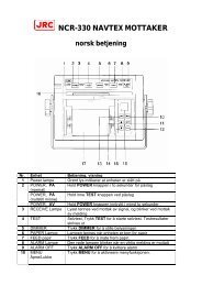
2. Names and Function of the Unit<br />
This section describes the names and functions of the control panel and its controls.<br />
12 11 2 1<br />
3<br />
4<br />
6 5<br />
10 9 8 7<br />
Figure 2-1 Control Panel<br />
No. Name Function<br />
1 ACK Cancels the buzzer.<br />
2 MENU Displays the menu.<br />
3 Arrows Move a cursor.<br />
4 ENT Selects an item.<br />
5 MODE Switches the display modes.<br />
6 CLR Clears an item.<br />
7<br />
PWR/PANEL<br />
Switches the equipment power on and off, adjusts the<br />
brightness of the panel. Press and hold both the<br />
PWR/PANEL and the BRILL keys to turn off the power.<br />
8 BRILL Adjusts the screen brilliance.<br />
9 DAY NIGHT Enhances the visibility of the screen.<br />
10 PRINT Starts printing.<br />
11 (RANGE) +/– Switches the depth range to shallow or deep.<br />
12 (GAIN) +/– Adjusts the sensitivity high or low.<br />
2. Names and Functions of the Unit 6
3. Display<br />
3.1 Standard mode (dual frequency)<br />
3. Display 7
3.2 History mode<br />
Keel height value<br />
3. Display 8
3.3 Docking mode<br />
3. Display 9
4. Operation<br />
4.1 Basic Operations<br />
Turning Power ON/OFF<br />
Turning Power On<br />
Press and hold the PWR/PANEL key for three seconds.<br />
Turning power OFF<br />
Press and hold both the PWR/PANEL and the BRILL keys for three seconds.<br />
Adjusting Control Panel Illumination<br />
PANEL<br />
Press the PWR/PANEL key, and use the arrow keys to adjust the control panel brightness.<br />
The control panel illumination can not be turned fully off, it can only be dimmed.<br />
Adjusting Screen Brilliance<br />
BRILL<br />
The screen brilliance is adjusted by pressing the BRILL key. Set the brilliance to optimum<br />
visibility by using the arrow keys.<br />
Note:<br />
Use the Day/Night Vision also to enhance the visibility of the screen depending in the<br />
surrounding light condition.<br />
4. Operation 10
Setting Depth Range<br />
Each time you press the (RANGE) + key, the measuring range increases in the sequence 10,<br />
20, 50, 100, 200, 500, 800 meters.<br />
Each time you press the (RANGE) – key, the measuring range decreases in the sequence<br />
800, 500, 200, 100, 50, 20, 10 meters.<br />
Note:<br />
1. As per the draft setting, the seabed image may shift outside the depth measuring range.<br />
2. You must display the seabed, otherwise you don’t see the depth value.<br />
Automatic Range<br />
In the Automatic range mode, the range scale is automatically adjusted.<br />
Turn on the power or press and hold both the (RANGE) + and – keys for three seconds.<br />
Once Automatic range mode is selected, the text “AUTO” will appear on the screen.<br />
The Automatic range mode is cancelled by pressing the (RANGE) + or – key.<br />
Note:<br />
1. The Automatic range mode can be set by a dedicated menu function.<br />
2. Default setting of the automatic range is 10m.<br />
4. Operation 11
Adjusting Receiver Sensitivity<br />
Select the step from 0 to 30.<br />
Pressing the (GAIN) + key increases sensitivity.<br />
Pressing the (GAIN) – key decreases sensitivity.<br />
If the receiver sensitivity is set too high, noise will also be displayed on the screen, making it<br />
difficult to distinguish the seabed. The seabed color should be orange, red or color between<br />
orange and red. Adjust the sensitivity to an appropriate value by monitoring the image<br />
being plotted on the screen. (See figure below)<br />
Increase<br />
sensitivity<br />
Good<br />
Decrease<br />
sensitivity<br />
Automatic Gain<br />
In the Automatic gain mode, the sensitivity is automatically adjusted.<br />
Press and hold both the (GAIN) + and – keys for three seconds. Once Automatic gain mode<br />
is selected, the text “GAIN:AUTO” will appear on the screen and LONG will be selected at<br />
STC function.<br />
The Automatic range mode is cancelled by pressing the (GAIN) + or – key.<br />
Note:<br />
1. The Automatic gain mode can be set by a dedicated menu function.<br />
2. Default setting of the automatic gain is 10 in the steps 0 to 20.<br />
4. Operation 12
Selecting Display Mode<br />
Pressing the MODE key choose the display mode among STANDARD, HISTORY, and<br />
DOCKING.<br />
[Single frequency]<br />
Each press of the MODE key brings up the display mode as follows, “Standard mode, History<br />
mode, Docking mode.”<br />
[Dual frequency]<br />
Each press of the MODE key brings up the display mode as follows, “Single frequency<br />
standard mode (primary), Single frequency standard mode (secondary), Dual frequency<br />
standard mode, Single frequency history mode (primary), Single frequency history mode<br />
(secondary), Docking mode.”<br />
Adjusting Screen Visibility<br />
Use the Day/Night Vision to enhance the visibility of the screen depending in the surrounding<br />
light condition.<br />
Select day1, day2, night1, or night2.<br />
Note:<br />
The color be set by a dedicated menu function.<br />
Canceling the Buzzer<br />
Press the ACK key to cancel the depth alarm buzzer.<br />
4. Operation 13
Menu Tree 1<br />
4. Operation 14
Menu Tree 2<br />
4. Operation 15
4.2 Menu Operations<br />
Selecting Item to set<br />
DISPLAY<br />
ALARM<br />
INITIAL<br />
PRINTER CONT<br />
COMMUNICATION<br />
MAINTENANCE<br />
><br />
><br />
><br />
><br />
><br />
><br />
Press the MENU key. The window shown above appears on the screen. While watching<br />
the display, use the arrow keys to select the item to be changed. The selected item is<br />
highlighted on the display. In the figure at above, "DISPLAY" is selected.<br />
When an item is highlighted, press the ENT key to change the setting.<br />
Switching to Normal Operation<br />
To switch to normal operating, press the CLR key several times.<br />
Note:<br />
You can press the MENU key also to return to normal operation at any time the menu<br />
window is displayed.<br />
4. Operation 16
Display Settings<br />
DISPLAY<br />
SCROLL SPEED<br />
CLUTTER<br />
INTERFERENCE<br />
GAIN<br />
RANGE<br />
DRAFT<br />
CURSOR<br />
FAST<br />
4<br />
OFF<br />
AUTO<br />
MANUAL<br />
6.1<br />
ON<br />
Scroll speed: Choose one among slow, standard, and fast.<br />
Clutter: Suppresses small noise. Choose one among 11 levels. “0” is the weakest.<br />
Interference: Eliminates noise from other boats. “OFF” does not eliminate the noise.<br />
“IR1” compares it with the last data. “IR2” compares it with the last two data. “IR3”<br />
compares it with the last three data.<br />
Gain: Choose manual or automatic.<br />
Range: Choose manual or automatic.<br />
Draft: Enter the desired value. The draft can be set between 0.0 and 50.0 m in steps of 0.1<br />
m.<br />
Cursor: “OFF” does not display the cursor. “ON” displays the cursor. “AUTO” displays the<br />
cursor for 30 seconds after the cursor movement is stopped.<br />
Alarm Settings<br />
ALARM<br />
KEY ACK<br />
RELAY MODE<br />
DEPTH ALARM<br />
SYSTEM ALARM<br />
ON<br />
CONTINUOUS<br />
><br />
><br />
Key acknowledgement: Enables / disables the keypads beep.<br />
Relay mode: Choose intermittent or continuous.<br />
4. Operation 17
Setting Depth Alarm<br />
DEPTH SETTING<br />
20.0<br />
Display the window shown above.<br />
Pressing and holding the upward-arrow key increases the depth setting of the depth alarm.<br />
Pressing and holding the downward-arrow key decreases the depth setting of the depth<br />
alarm.<br />
Press the ENT key to finish setting.<br />
If the measured depth is less than the set depth alarm value, a warning character blinks and<br />
the buzzer sounds.<br />
Notes:<br />
1. The buzzer sounds for depth, power fail, and system alarms. You can check which alarm<br />
is being issued from the blinking characters.<br />
2. If, due to bubbling, etc., it is not possible to discriminate the sea bottom, it is also not<br />
possible to trigger the depth alarm. When sailing in shallow waters, please check the sea<br />
bottom reflected on the screen.<br />
3. The alarm tone sounds from the hole at the front panel. Do not block this hole.<br />
The currently set depth alarm is displayed on the screen.<br />
Note:<br />
The depth can be set between 0.0 and 99.9 meters.<br />
Activating/deactivating the alarm<br />
Highlight the alarm item you wish to activate or deactivate.<br />
Select OFF to deactivate the alarm.<br />
Select ON to activate the alarm.<br />
Press the ENT key to finish setting.<br />
4. Operation 18
Initial Settings<br />
INITIAL<br />
MEMORY INTERVAL<br />
COLOR<br />
DEPTH DISPLAY MODE<br />
PRIMARY<br />
SECONDARY<br />
DATE/TIME<br />
30S<br />
><br />
TRAN<br />
><br />
><br />
><br />
Memory interval: “30S” saves the sounding data every 24 hours. “1min” saves the<br />
sounding data every 12 hours.<br />
Color: Adjust color of the screen and character for the DAY NIGHT key.<br />
Depth display mode: “SURF” displays the depth below water surface. “TRAN” displays<br />
the depth below the transducer. “KEEL” displays the depth below the keel. (see figure A)<br />
Primary: Enter the data of the primary transducer; frequency, position, STC, inner, and keel.<br />
Secondary: Enter the data of the secondary transducer; frequency, position, STC, inner, and<br />
keel.<br />
Date/time: Set the time, the date, and a time difference. GPS synchronization “OFF” uses<br />
the inner clock. GPS synchronization “ON” uses the ZDA data to synchronize the inner<br />
clock.<br />
4. Operation 19
Printer Control Settings<br />
PRINTER CONT<br />
PRINTER<br />
PRINT MODE<br />
LOG LENGTH<br />
SPEED<br />
ON<br />
COPY<br />
10min<br />
4800bps<br />
Printer: Enables / disables to print.<br />
Print mode: “COPY” prints the data displayed on the present screen. “HISTORY” prints all<br />
the saved data graphically. “LOG” prints a specific period of the saved data.<br />
(see figure C for example)<br />
Log length: Choose a log length for “LOG” which explained just above.<br />
Speed: Choose a baud rate of the printer port.<br />
4. Operation 20<br />
Figure C
Setting Format for Depth Data Output<br />
DEPTH<br />
Ver1.5<br />
Ver2.3<br />
ALL<br />
Display the window shown above. The format changes each time you press the up or<br />
downward-arrow key.<br />
Notes:<br />
1. There are three output formats: NMEA0183V2.3, NMEA0183V1.5, or ALL.<br />
2. In the case of NMEA0183V2.3, only "SDDPT" sentences are output.<br />
$SDDPT, xxx.x, x.x, x.x *hh (CR)(LF)<br />
(1) (2) (3) (4)<br />
(1) Depth measured from the transducer regardless of the depth display mode setting (in<br />
meters only.)<br />
(2) According to the depth display mode:<br />
DISP-SURF: Draft value (no + or – sign preceding values)<br />
DISP-TRANS: 0.0<br />
DISP-KEEL: Keel height compensation (– sign preceding values)<br />
(3) Measuring range: RANGE (in meters only)<br />
(4) Checksum (result after each ASCII code of every character between "S" just after "$" and<br />
"X" just before " * " is EXORed.)<br />
3. In the case of NMEA0183V1.5, the output sentence varies according to the depth display<br />
mode setting.<br />
• When DISP-SURF is set, only the "SDDBS" sentence is output.<br />
$SDDBS, xxx.x, f, xxx.x, M, xxx.x, F(CR)(LF)<br />
(1) (2) (3)<br />
• When DISP-TRANS is set, only the "SDDBT" sentence is output.<br />
$SDDBT, xxx.x, f, xxx.x, M, xxx.x, F(CR)(LF)<br />
(1) (2) (3)<br />
• When DISP-KEEL is set, only the "SDDBK" sentence is output.<br />
$SDDBK, xxx.x, f, xxx.x, M, xxx.x, F(CR)(LF)<br />
(1) (2) (3)<br />
The field values are the same in each of the three sentence types:<br />
(1) Depth value after compensation (in feet)<br />
(2) Depth value after compensation (in meters)<br />
(3) Depth value after compensation (in fathoms)<br />
(4) No check sum<br />
4. Operation 21
Setting Output Alarm Signal<br />
ALARM<br />
OFF<br />
ON<br />
Display the window shown above. Use the arrow keys to select OFF or ON.<br />
When OFF is selected, ALR sentence is not output.<br />
When ON is selected, ALR sentence is output according to the depth and system alarm<br />
setting.<br />
Notes:<br />
ALR(Set Alarm State)<br />
$SDALR,hhmmss.ss,xxx,A,A,c--c*hh<br />
(1) (2) (3)(4)(5)<br />
1. Time of alarm condition change,UTC<br />
2. ID number of the alarm source<br />
351 primary depth alarm<br />
352 secondary depth alarm<br />
353 primary depth lost<br />
354 secondary depth lost<br />
356 recording paper is not good<br />
357 printer connection is not good<br />
360 primary output data is not good<br />
361 primary input data is not good<br />
362 primary input sensitivity data is not good<br />
363 secondary output data is not good<br />
364 secondary input data is not good<br />
365 secondary input sensitivity data is not good<br />
366 backup data area is not good<br />
3. Alarm condition (A = threshold exceeded, V = not exceeded)<br />
4. Alarm's acknowledge state (A = acknowledged, V = unacknowledged)<br />
5. Alarm's description text<br />
4. Operation 22
Setting Output System Signal<br />
SYSTEM<br />
OFF<br />
ON<br />
Display the window shown above. Use the arrow keys to select OFF or ON.<br />
When OFF is selected, a cyclical PJRC is not output.<br />
When ON is selected, PJRC, PJRCL, and PJRCM is output to the depth output port.<br />
Setting Output Printer Port Out Signal<br />
PRINTER PORT OUT<br />
PRINTER<br />
PC<br />
Display the window shown above. The mode switches each time you press the up or<br />
downward-arrow key.<br />
When PRINTER is selected, a printer control signal is output.<br />
When PC is selected, PJRCP is output according to the print mode setting. PJRCM is<br />
output after PJRCP.<br />
Notes:<br />
1. Any settings output PJRCU every 1 second.<br />
2. Output sentence and source<br />
PJRCU depth, offset, selected range<br />
PJRCL maintenance<br />
PJRCM system data<br />
PJRCP print data<br />
4. Operation 23
Memory Test<br />
SELF TEST<br />
CONTROL UNIT<br />
LCD UNIT<br />
KEY UNIT<br />
PRINTER TEST<br />
ALARM TEST<br />
><br />
><br />
><br />
><br />
><br />
><br />
Display the window shown above. Use the up or downward-arrow key to select CONTROL<br />
UNIT.<br />
Press the ENT key to start the memory test.<br />
The results of the memory test are shown on the screen.<br />
• During testing, nothing is shown on the screen.<br />
• The results are shown for each PROM, SRAM, and VRAM.<br />
If OK : OK<br />
If no good : NG<br />
If NG is displayed, the Transducer Controller is faulty and requires servicing. (See the list of<br />
offices at the end of this manual.)<br />
LCD Check<br />
SELF TEST<br />
CONTROL UNIT<br />
LCD UNIT<br />
KEY UNIT<br />
PRINTER TEST<br />
ALARM TEST<br />
><br />
><br />
><br />
><br />
><br />
><br />
Display the window shown above. Use the up or downward-arrow key to select color.<br />
Press the CLR key to exit.<br />
This test fills the whole screen with colors, which are black, red, green, blue, and white. The<br />
color changes each time you press the up or downward-arrow key. If there is any dropout,<br />
the Panel or Transducer Controller may be faulty. Please contact JRC or its agent. (See<br />
the list of offices at the end of this manual.)<br />
4. Operation 24
Panel Circuit Operation Check<br />
KEY UNIT<br />
BRILL<br />
Display the window shown above.<br />
Press each location on the panel.<br />
• If operation is OK, a key name is displayed in the key unit window. In the figure at above,<br />
the result of that the BRILL key is pressed.<br />
• If operation is NG, nothing remains.<br />
If faulty, the Panel or Transducer Controller may be faulty and may require servicing. (See<br />
the list of offices at the end of this manual.)<br />
Printer Test<br />
SELF TEST<br />
CONTROL UNIT<br />
LCD UNIT<br />
KEY UNIT<br />
PRINTER TEST<br />
ALARM TEST<br />
><br />
><br />
><br />
><br />
><br />
><br />
Display the window shown above. Use the up or downward-arrow key to select PRINTER<br />
TEST.<br />
Press the ENT key to start the recording paper surface check.<br />
This check prints a test pattern on the recording paper. (See figure B for example) If the<br />
printing is blurred, it may be faulty and may require servicing. Please contact JRC or its<br />
agent. (See the list of offices at the end of this manual.)<br />
Figure B<br />
4. Operation 25
Alarm Test<br />
“OFF” disables the alarm test. “DEPTH ALARM” displays the center of the depth scale.<br />
“SYSTEM ALARM” enables the preset depth lost alarm.<br />
Maintenance Functions<br />
MAINTENANCE<br />
SELF TEST<br />
ALARM LOG<br />
ALARM LOG OUT<br />
ALARM LOG DEL<br />
LINE MONITOR<br />
RX MONITOR<br />
SYSTEM No.<br />
><br />
><br />
><br />
><br />
><br />
><br />
><br />
Alarm log: Displays the alarm log by pressing the ENT key. Pressing the CLR key brings<br />
up the Maintenance Menu window.<br />
Alarm log out: Outputs the alarm log to the normal port, the printer, or the printer port by<br />
pressing the ENT key.<br />
Alarm log deletion: Deletes all the alarm log by pressing the ENT key.<br />
Line monitor: “NAV/DEPTH” displays the Input/output data of navigation and depth by<br />
pressing the ENT key. “ALR” displays the Input/output data of ALR by pressing the ENT key.<br />
“PRINTER” displays the Input/output data of the printer port by pressing the ENT key.<br />
Pressing the CLR key brings up the Maintenance Menu window.<br />
RX monitor: Displays the present status of the receiver by pressing the ENT key.<br />
Program Version No.<br />
SYSTEM No.<br />
07/09/2006<br />
Ver 00.03<br />
The program version No. is displayed on the system number window.<br />
4. Operation 26
5.3 Master Reset<br />
Executing Standard Default Settings<br />
Turn OFF the power, then turn ON the power while simultaneously pressing and holding both<br />
the MENU and CLR keys.<br />
After resetting the equipment to the standard defaults, the frequency setting menu window,<br />
which said please do connection setting of transducers, appears on the screen.<br />
You cannot abort this operation after the frequency setting menu window appeared on the<br />
screen. You have to select the frequency to switch to normal operation.<br />
Note:<br />
See Menu tree for the standard defaults.<br />
4. Operation 27
5. Replacing Consumables<br />
5.1 Replacing Recording Paper<br />
Be sure to replace with the recording paper specified by JRC.<br />
Name<br />
Recording paper<br />
Remarks<br />
The red line will appear when there is only about one meter of<br />
recording paper left on the roll.<br />
Handle the paper cutter carefully not to cut your hand.<br />
(1) Press the paper cover open button, and open the paper cover.<br />
(2) Set a paper roll as shown in the figure.<br />
5. Replacing Consumables 28
(3) Close the paper cover by pressing the both ends of the cover, with the tip end of the<br />
paper emerging from the printer.<br />
Note:<br />
Turn off the power before you open the paper cover, otherwise warring alarm goes off.<br />
5. Replacing Consumables 29
5.2 Replacing the Fuses<br />
Use only the specified fuses, and check the cause of the fuses blowing before replacing<br />
them. Be sure to turn OFF the main power switch (to the side marked O) on the power<br />
supply (CQD-2083) before replacing the fuses.<br />
No. Type No. Spec. Part Code Remarks<br />
F1 250V 1A TLC 5A 250V 1A 5ZFCA00147<br />
F2 MF51NR 250V 0.5 250V 0.5A 5ZFGD00019<br />
F3 MF51NR 250V 2 250V 2A 5ZFGD00022<br />
Fuse Positions<br />
5. Replacing Consumables 30
(1) Replacing Main Power Supply Fuse F1<br />
One reason for this fuse blowing is a faulty cable attached to the power supply. Check the<br />
cables before replacing the fuse, then turn the power on. If the fuse blows again, the Power<br />
Supply (CBD-1811) may be faulty. Contact JRC or its agent.<br />
(2) Replacing 24VDC Input Power Fail Alarm Fuse F2<br />
One reason for this fuse blowing is the input of an abnormal voltage. Check the input<br />
voltage at J11 pins (3) and (4) of the Interface Block. Check that the voltage is as rated<br />
(24VDC) (operating voltage: 21.5 to 31.5VDC) before replacing the fuse. If the fuse blows<br />
again, the Interface Block (CGD-2083), the Power Supply (CBD-1811), the Control Block<br />
(OCK-963), or the Cables (CFQ-9139, CFQ-9140, CFQ-9148) may be faulty. Contact JRC<br />
or its agent. (See the list of offices at the end of this manual.)<br />
(3) Replacing Built-in Printer Fuse F3<br />
One reason for this fuse blowing is an overcurrent in a built-in printer or an external device<br />
connected to J13 pins (1) and (2) of the interface block. Temporarily remove the cable to<br />
the external device. If the fuse blows again, the Interface Block (CQD-2083), the built-in<br />
printer (DPU30-OBJ-E), or the cable (CFQ-9142) may be faulty. Contact JRC or its agent.<br />
(See the list of offices at the end of this manual.)<br />
5. Replacing Consumables 31
6. Consider Installation<br />
• Do not install the <strong>JFE</strong>-<strong>680</strong> where subject to the following conditions as such conditions may<br />
cause failures and reduce the life of the equipment.<br />
1. Where liable to be splashed with water.<br />
2. Where ventilation is poor.<br />
• Do not coat the part of the transducer that outputs the ultrasonic waves (the rubber part of<br />
the tank on the ship's bottom) with the hull coating as this will deteriorate performance.<br />
6. Consider Installation 32
7. Installation<br />
When installing the equipment, securely connect the earth lead to the earth<br />
terminal.<br />
Failure to connect the earth may result in electric shock in the event of a fault or<br />
power leak developing.<br />
Do not install or operate the equipment where subject to temperatures 55°C or<br />
higher or –15°C or lower.<br />
Failure to observe this caution may result in fire or damage.<br />
Do not install the equipment on unstable or unlevel surfaces. Failure to<br />
observe this condition may result in the equipment falling or toppling over,<br />
resulting in injury.<br />
Take care when laying the transducer cable, power cable, and earth lead as<br />
positioning has an affect on electromagnetic interference. There is a risk of<br />
interfering with other equipment or the echo-sounder being interfered with by<br />
the other equipment.<br />
After installing the echo-sounder, turn on the power to all other equipment to<br />
check for interference with or from all the equipment. Interference may cause<br />
malfunctions.<br />
7. Installation 33
7.1 Installing the Recorder Unit<br />
Flush-Mounted Equipment<br />
7. Installation 34<br />
Figure 3-1
Wall-Mounted Equipment<br />
Figure 3-2<br />
7. Installation 35
7.2 Installing the Transducer<br />
The external dimensions illustrated below are for the standard equipment. Please refer to<br />
the separately supplied drawings if your specifications are not standard.<br />
NKF-341<br />
7. Installation 36
NKF-345<br />
7. Installation 37
NKF-392C<br />
7. Installation 38
7.3 Connecting Components<br />
Notes:<br />
1. The shield of each cable must be securely attached to the connectors and must not<br />
contact any other connectors, etc.<br />
2. Casings must be grounded securely to the ship’s hull using copper plates.<br />
3. The exterior is to be grounded to the ship’s hull cable bands.<br />
4. Select NC/NO for Depth Alarm and Power Fail Alarm.<br />
7. Installation 39
8. Troubleshooting<br />
The table below provides simple troubleshooting procedures which you may follow to restore<br />
normal operation. If you cannot restore normal operation, contact your dealer.<br />
SYMPTOM PROBABLE CAUSES REMEDY<br />
No picture<br />
The power cord is not plugged Plug the power cord<br />
The power cord is damaged Repair the cord<br />
The breaker of your ship is off Turn on the breaker<br />
High or low power supply Check the supply voltage<br />
Fuse blown<br />
Replace the fuse<br />
No echo sounding picture Transducer cable is not Connect the cable<br />
connected<br />
Transducer cable damaged Repair the cable<br />
Transducer is not connected Connect the transducer<br />
Wrong installation of the<br />
transducer<br />
Check the transducer<br />
Frequency setting is wrong Check the frequency setting<br />
Irregular display<br />
Low sensitivity<br />
Increase the gain<br />
Muddy seabed<br />
Increase the gain<br />
Marine life on the transducer Remove marine life from the<br />
transducer.<br />
The transducer is damaged Replace the transducer<br />
Draft value is not collect Adjust draft value<br />
Suspect dirty water<br />
Decrease the gain<br />
Heavy noise<br />
Noise from generator<br />
Check the generator<br />
Wrong installation of the Relocate the ground wire<br />
ground wire<br />
The transducer cable is<br />
damaged<br />
Repair the transducer cable<br />
The transducer cable and the<br />
power code are placed too<br />
close.<br />
Relocate the transducer<br />
cable and the power code<br />
not too close.<br />
The printer won’t start Fuse blown Replace the fuse<br />
8. Troubleshooting 40
9. After-sales Service<br />
9.1 When Requesting Servicing<br />
If you suspect a fault, stop using the equipment and contact JRC or its agent.<br />
Servicing Under Warranty<br />
When the fault develops while the equipment is being used as indicated in the Instruction<br />
Manual, the equipment will be repaired free of charge. However, if the fault occurs as the<br />
result of misuse, negligence, natural disaster, fire, or other acts of God, a charge will be<br />
made for its repair.<br />
Servicing Out of Warranty<br />
If the fault can be rectified by servicing the equipment, the repair will be made at your<br />
expense.<br />
Details to be Submitted<br />
- Name, type No., month and year of manufacture, and serial number;<br />
- Nature of fault (in as much detail as possible);<br />
- Contact details (your name, address and phone number, etc.)<br />
9.2 Recommendations for Inspection and Maintenance<br />
Depending on the conditions of usage, the performance may deteriorate due to the aging of<br />
components. In such conditions, please consult JRC or its agent for inspection and<br />
maintenance, as distinct from the daily care you normally give your equipment.<br />
Note that such inspection and maintenance is subject to charge.<br />
Please consult JRC or its agent for further details of any part of the afterservice conditions.<br />
Contact: See list at end of manual.<br />
9. After-sales Service 41
10. Disposal<br />
10.1 Disposal of this equipment<br />
Please dispose of this equipment following the guidelines of the local body governing the<br />
location at which the equipment is disposed of.<br />
10. Disposal 42
11. Specifications<br />
Display<br />
10.4 inch TFT LCD (640 x 480 pixels)<br />
Frequency 200kHz / 50kHz<br />
Echo color 8 colors or 8 level monochrome<br />
Digital depth 4 digit (0.1m)<br />
Range<br />
10, 20, 50, 100, 200, 500, 800m<br />
Depth accuracy ±2.5%<br />
Minimum<br />
sounding depth<br />
200kHz : 1.0m, 50kHz : 2m<br />
Draft adjust 50m in 0.1m steps<br />
171PRR (10, 20, 50m)<br />
TX pulse<br />
86PRR (100, 200m)<br />
repetition rate<br />
43PRR (500, 800m)<br />
Presentation<br />
mode<br />
Standard, History, Docking<br />
Time range of<br />
echo display<br />
5, 10, 20, 30min<br />
Auto function Gain, Range<br />
Alarm function Depth, Power fail, System error<br />
Preview function 24hour<br />
Transducer<br />
200kHz : UT-200ND<br />
50kHz : UT-50MD<br />
Power supply<br />
100-115/200-230VAC±15%, 50Hz/60Hz±5%<br />
24VDC (only use for power fail monitoring)<br />
Power<br />
consumption<br />
Less than 50W<br />
Water proofing IPX2 drip proof<br />
Input nav. data IEC61162-1NMEA0183 RMA, RMC, GGA, GLL, VTG, ZDA<br />
Input ACK signal<br />
Input signals<br />
IEC61162-1NMEA0183 ALR<br />
Power fail alarm ACK:<br />
(Contact input: 12VDC 2.4mA, current control: 12VDC 1.2mA)<br />
Depth alarm ACK, System alarm ACK:<br />
(Contact input: 5VDC 5mA, current control: 12VDC 1.2mA)<br />
Output depth<br />
value data<br />
IEC61162-1 (NMEA0183 V1.5)<br />
IEC61162-1 (NMEA0183 V2.3)<br />
DBS, DBT, DBK<br />
DPT<br />
every 1 second<br />
every 1 second<br />
Output alarm data IEC61162-1 (NMEA0183) ALR every 1 second<br />
Output system<br />
data<br />
(IEC61162-1)<br />
PJRCL<br />
PJRCM (90)<br />
PJRCM (88, 89)<br />
UTC<br />
UTC<br />
every 10 seconds<br />
every 0 to 4 hours<br />
every 0 to 4 hours<br />
Output PC data<br />
Output signals<br />
Ambient<br />
temperature<br />
Relative humidity<br />
PJRCP<br />
Power fail alarm, Depth alarm, System alarm:<br />
(Relay contact output: rated load 120VAC 10A, 30VDC 8A, NO/NC)<br />
–15°C to 55°C / operating<br />
–25°C to 70°C / storage<br />
less than 93%RH under 40°C condition (non-condensing) / operating<br />
less than 93%RH under 40°C condition (non-condensing) / storage<br />
11. Specification 43
Appendix<br />
Noise<br />
Bubble Noise<br />
Bubble Interruption<br />
Interference Noise from other ship<br />
Plankton layer<br />
Appendix 44
Actual Pictures<br />
Seabed<br />
Zero line<br />
DISP TRANS<br />
DISP SURF<br />
DISP KEEL<br />
figure A<br />
Seabed<br />
Zero line<br />
Third reflection of bottom<br />
Second reflection of bottom<br />
Seabed<br />
In case of a shallow seabed or when increasing the amplifier sensitivity, two seabed lines<br />
may be recorded. This results from a multi-reflection of ultra-sonic wave between the<br />
seabed and hull bottom or surface of sea, in such manner: An emitted ultrasonic wave once<br />
reflected at the seabed returns toward the transducer or surface or sea but reflected at the<br />
hull bottom or surface of sea and again reflected at the seabed toward the transducer.<br />
Such multiple recording of the seabed may appear due to change of bottom quality. A<br />
double or triple reflection may be sometimes recorded.<br />
In any case, a first reflection recording from the zero line represents a real seabed return. A<br />
first, second and third reflection lines of seabed arrange with approximately equal spacing on<br />
the recording.<br />
In addition, the shade of the reflection lines fades little by little away from the fast line on the<br />
recording. From these conditions, they can be easily identified as a multireflection.<br />
Appendix 45
Seabed Quality Change<br />
Mud<br />
Rock<br />
In case of a hard seabed composed of rocks etc., its return trails long, as shown in right chart.<br />
In case of a soft seabed made of mud, seaweed, etc., they poorly reflect an ultrasonic wave<br />
to result in thin recording of the seabed with short trail.<br />
The seabed quality can be more sufficiently identified with use of wider beam angle and<br />
longer pulsewidth.<br />
Usually lower frequency is used.<br />
Appendix 46
Abrupt-Sloped Seabed<br />
Sidelobe<br />
False echo<br />
A dim echo may sometimes appear along an abrupt slope of seabed, as if it were floating<br />
above the slope, when recording.<br />
In case of flat seabed, thin second return of seabed may sometimes appear, which is slightly<br />
below the actual seabed.<br />
In either case, the dim or thin echoes are false and produced by sidelobes of ultrasonic beam<br />
from the transducer. Any false echo is thinner than and parallel to a real echo.<br />
Appendix 47
The echo of a seabed with abrupt slope is recorded as a lone difficult to see and less<br />
discriminative, since it tends to accompany with a false echo due to the sidelobe and the<br />
inherent property of directivity.<br />
In particular, a seabed with abrupt slope and heavily rugged surface provided an echo very<br />
difficult to display on the recording.<br />
Appendix 48
7ZPNB0043<br />
电 子 信 息 产 品 有 害 物 资 申 明<br />
日 本 无 线 株 式 会 社<br />
Declaration on toxic & hazardous substances or elements<br />
of Electronic Information Products<br />
Japan Radio Company Limited<br />
有 毒 有 害 物 质 或 元 素 的 名 称 及 含 量<br />
(Names & Content of toxic and hazardous substances or elements)<br />
形 式 名 (Type): <strong>JFE</strong>-<strong>680</strong><br />
部 件 名 称<br />
(Part name)<br />
名 称 (Name): Echo Sounder<br />
有 毒 有 害 物 质 或 元 素<br />
(Toxic and Hazardous Substances and Elements)<br />
铅 汞 镉 六 价 铬 多 溴 联 苯 多 溴 二 苯 醚<br />
(Pb) (Hg) (Cd) (Cr 6+ ) (PBB) (PBDE)<br />
记 录 装 置<br />
(Recorder Unit)<br />
× × × × × ×<br />
船 底 装 置<br />
(Hull-Bottom Unit)<br />
× × × × × ×<br />
外 部 设 备 (Peripherals)<br />
・ 选 择 (Options)<br />
・ 打 印 机 (Printer)<br />
・ 电 线 类 (Cables)<br />
・ 手 册 (Documennts)<br />
× ○ × × × ×<br />
○: 表 示 该 有 毒 有 害 物 质 在 该 部 件 所 有 均 质 材 料 中 的 含 量 均 在 SJ/T11306-2006 标 准 规 定 的 限 量 要 求 以 下 。<br />
(Indicates that this toxic, or hazardous substance contained in all of the homogeneous materials for this part is below the requirement in<br />
SJ/T11363-2006.)<br />
×: 表 示 该 有 毒 有 害 物 质 至 少 在 该 部 件 的 某 一 均 质 材 料 中 的 含 量 超 出 SJ/T11363-2006 标 准 规 定 的 限 量 要 求 。<br />
(Indicates that this toxic or hazardous substance contained in at least one of the homogeneous materials used for this part is above<br />
the limit requirement in SJ/T 11363-2006.)<br />
JRC Code No. :<br />
7ZPNA2012<br />
RE: 中 华 人 民 共 和 国 电 子 信 息 产 品 污 染 控 制 管 理 办 法<br />
Management Methods on Control of Pollution from Electronics Information Products of the People's Republic of China<br />
- 1 / 1 -
For further information,contact:<br />
Not use the asbestos<br />
CODE No.7ZP<br />
Marine Service Department<br />
Telephone : +81-3-3492-1305<br />
Facsimile : +81-3-3779-1420<br />
e-mail : tmsc@jrc.co.jp<br />
AMSTERDAM Branch<br />
Telephone : +31-20-658-0750<br />
Facsimile : +31-20-658-0755<br />
e-mail : service@jrcams.nl<br />
SEATTLE Branch<br />
Telephone : +1-206-654-5644<br />
Facsimile : +1-206-654-7030<br />
e-mail : service@jrcamerica.com<br />
01ETM<br />
URL<br />
http://www.jrc.co.jp<br />
ISO 9001, ISO 14001 Certified<br />
. 200 Editi JRC<br />
Printed in Japan