Orifice Nozzle Valve
R Series Multi Orifice Nozzle Choke Valve - Brice Barclay
R Series Multi Orifice Nozzle Choke Valve - Brice Barclay

You also want an ePaper? Increase the reach of your titles
YUMPU automatically turns print PDFs into web optimized ePapers that Google loves.
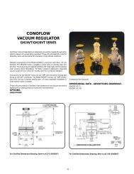
Multi<br />
<strong>Orifice</strong><br />
<strong>Nozzle</strong><br />
(MON)<br />
<strong>Valve</strong><br />
R Series Control <strong>Valve</strong>s R2 R3 R4 R6 R8
R Series Control <strong>Valve</strong>s<br />
www.taylorvalve.com<br />
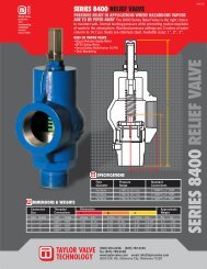
The applied principle of<br />
Hydrodynamic Energy Conversion<br />
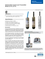
Protective<br />
Cage and<br />
Seat Assembly<br />
Protective<br />
Cage and<br />
Seat Assembly<br />
FLOW<br />
FLOW<br />
FLO W<br />
FLOW<br />
<strong>Nozzle</strong><br />
<strong>Nozzle</strong><br />
Side view of the fluid<br />
flow through the valve.<br />
View looking down<br />
from the top of the<br />
trim to the outlet of<br />
the valve.<br />
<strong>Valve</strong> Body<br />
NOTE: External control sleeve has been omitted in the illustration to provide clarity<br />
When the the valve valve is open is and open flowing, and the flowing fluid enters through the inlet flow of is the circulated valve into the cage<br />
inlet assembly, of the flow valve is circulated into the in the cage annulus assembly, created the by nozzle the cage, and the nozzle the and sleeve. the sleeve.<br />
in The the symmetry annulus of the created ports in the by nozzle the cause cage, the high velocity fluid streams created by the<br />
The pressure symmetry drop to collide of the into ports each in other the nozzle in the center cause to of the collide trim. high The into velocity impact each of fluid the other fluid<br />
streams converts most created of the energy by the and protects pressure the drop downstream of the components fluids converts from erosion. most<br />
in the centerline of the trim. The impact components from<br />
of erosion. the energy and protects the dowmstream
Taylor <strong>Valve</strong> Technology, Inc.<br />
405.787.0145 USA<br />
We Are Taylor <strong>Valve</strong>…<br />
…A pioneer in the design, development and manufacturing of valves and precision<br />
instrumentation to meet your pressure, flow and measurement needs.<br />
Every Taylor product is designed to meet the highly demanding requirements of oil<br />
and gas producers, refiners, chemical plant operators, power generators and the<br />
processing industry in order to more effectively control their liquid, steam or gas<br />
operations. Our promise is to meet these needs in an economical, yet operationally<br />
safe and environmentally responsible manner.<br />
Quality API and ASME Code valves and instrumentation can be shipped from Taylor’s<br />
facility in the United States quickly and reliably anywhere in the world.<br />
Taylor products are precisely designed for superior function utilizing the latest<br />
developments in materials and design practices in order to meet the most<br />
demanding specifications of the process applications for which our<br />
products are manufactured. This commitment yields a totally<br />
engineered product in both form and function.<br />
Superior flow characteristics and capacities are the cornerstone of<br />
Taylor’s technology, performing unlike any other flow control<br />
products due to their unique design, precise manufacturing and<br />
uncompromising quality – an emphasis proven by more than 100<br />
U.S. and foreign patents and nearly 50 years of service.<br />
DESIGN BENEFITS<br />
The R Series <strong>Valve</strong> features several unique design characteristics<br />
that minimize wear and maximize service life. The cage and external<br />
sleeve trim is designed to contain turbulence and wear by centralizing<br />
the flow in the nozzle bore causing instream flow impingement<br />
(hydrodynamic conversion). The valve body and outlet are protected from<br />
wear because the energy conversion created by the pressure drop is contained<br />
in the trim cavity before flow enters the outlet. This eliminates the typical problems<br />
of wear in the valve outlet.<br />
CONTROL ELEMENT<br />
The Taylor R Series trim consists of a multi orifice flow nozzle (MON) and external<br />
sliding sleeve. The trim design provides accurate control by the use of a system of<br />
precision orifices in the flow nozzle. The orifice configuration produces an<br />
equal-percentage flow characteristic offering maximum control throughout a broad<br />
range of operation.<br />
The exceptionally high turndown ratio (100:1 turndown ratio) provides a broad control<br />
range. The result is excellent versatility. What does this mean? One set of trim.<br />
Utilizing a cartridge system, all trim and wear parts are attached to the bonnet,<br />
making the servicing and inspection of the valve body and trim extremely easy.
Taylor <strong>Valve</strong> Technology, Inc.<br />
405.787.0145 USA<br />
Features of of “R” “R” <strong>Valve</strong> Design design<br />
Geared Handwheel<br />
operator reduces<br />
torque and provides<br />
precision positioning<br />
of trim<br />
Heavy thrust bearings<br />
provide reduced<br />
torque and smooth<br />
operation<br />
Visual Position<br />
indication in 1/64th”<br />
Lubrication port for<br />
stem and thread<br />
lubrication<br />
Stainless Steel Bonnet<br />
seal ring (optional)<br />
Anti-rotation pin to<br />
restrict rotational<br />
movement of stem<br />
Chevron-type<br />
packing with spring<br />
load<br />
Protective cage<br />
Fully Guided Stem<br />
reduce side load<br />
and vibration<br />
Pressure Balanced<br />
Trim<br />
Fully guided sleeve<br />
reduces side load<br />
and stops vibration<br />
Bleed <strong>Valve</strong> to allow<br />
pressure to be<br />
released<br />
Cross section of wear<br />
resistant material to<br />
extend service life<br />
Reverse Angle on<br />
Sleeve<br />
Precision <strong>Orifice</strong>s<br />
Separate shut off<br />
provides ANSI Class VI<br />
seal<br />
Stand alone flow<br />
nozzle is geometrically<br />
designed for wear<br />
and noise reduction
R Series Control <strong>Valve</strong>s<br />
405.787.0145 USA<br />
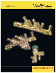
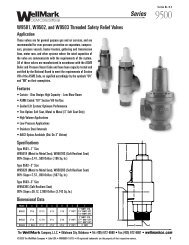
Multi <strong>Orifice</strong> <strong>Nozzle</strong> Technology<br />
Multi <strong>Orifice</strong> Cage Technology<br />
Multi <strong>Orifice</strong> <strong>Nozzle</strong><br />
Closed<br />
Position<br />
Open<br />
Position<br />
The Multi <strong>Orifice</strong> <strong>Nozzle</strong> (MON) trim configuration<br />
has been field-tested and proven to deliver<br />
superior wear resistance and control<br />
performance. The MON trim controls high velocity<br />
fluid during pressure reduction by directing the<br />
flow to the center of the flow nozzle. The erosive<br />
energy is contained and converted within the<br />
flow trim. As a result of this conversion, the valve<br />
outlet is protected from high velocity flow<br />
impingement.<br />
The wear is isolated to the expendable trim<br />
components instead of the valve wall which, in<br />
turn, reduces the potential for release of fluids to<br />
the environment.<br />
Debris space<br />
and liquid seal<br />
CLOSED<br />
OPEN<br />
Debris Trap<br />
Tri-Seat is<br />
protected from<br />
flow erosion<br />
Replaceable Seat<br />
Design<br />
FLOW<br />
FLOW<br />
Control Surface<br />
separate from<br />
Sealing Surface<br />
Tri-Seat<br />
provides ANSI<br />
Class VI Seal<br />
Control Surface<br />
separate from<br />
shut off seal<br />
Replaceable Flow<br />
<strong>Nozzle</strong> valve will<br />
function with part<br />
removed<br />
Sealing surface<br />
out of normal<br />
flow path and<br />
protected from<br />
erosion<br />
Replaceable<br />
flow nozzle is<br />
the wear<br />
compontent
R Series Control <strong>Valve</strong>s<br />
www.taylorvalve.com<br />
Control Choke <strong>Valve</strong> Standard Materials of Construction<br />
Component<br />
Low Temp Full SS Duplex<br />
API Temp Rating P-V L P-V P-V<br />
API Service Rating AA, BB, DD, EE EE CC, FF FF, HH<br />
<strong>Valve</strong> Body/Bonnet AISI 4130 AISI 4130 AISI 410 SS Duplex UNS 31803<br />
ASTM A182 F6NM Super Duplex UNS 32760<br />
Bolting* ASTM A193 B7 ASTM A320 L7M A193 B7* ASTM A320 L7M<br />
ASTM A453 Gr660<br />
<strong>Valve</strong> Stem 17-4 PH SS 17-4 PH SS 17-4 PH SS Inconel 625<br />
Wetted Parts 17-4 PH SS 17-4 PH SS 17-4 PH SS Inconel 625<br />
316 SS 316 SS 316 SS Inconel 718<br />
410 SS 410 SS 410 SS<br />
Tung. Carb Tung. Carb Tung. Carb<br />
API Flange AISI 4130 AISI 4130 AISI 4130 Duplex UNS 31803<br />
ASTM A105 ASTM A182 F6NM Super Duplex UNS 32760<br />
ANSI Flange ASTM A105 ASTM A350 GR LF2 AISI 410 SS Duplex UNS 31803<br />
ASTM A182 F6NM Super Duplex UNS 32760<br />
* Bolting can be zinc or Xylan coated if required.<br />
Trim Material Selection<br />
Based on Material Class and Flow Service<br />
Material Class Service Wear Components Non-Wear Components<br />
Available Materials for Seals<br />
Seal Type<br />
Stem Packing<br />
Static Bore Back-Up<br />
Rings*<br />
* Other materials available based on application.<br />
Sealing Materials<br />
Nitrile, Fluorocarbon,<br />
PTFE / 316 Spring Mtl.<br />
Nitrile, PTFE<br />
AA, BB, CC Non-Erosive 17-4 SS 17-4 SS<br />
DD, EE, FF Erosive Tungston Carbide 17-4 SS<br />
Cavitation Stellite TM 17-4 SS<br />
HH Non-Erosive Inconel 718 Inconel 718<br />
Erosive Tungston Carbide Inconel 718<br />
<strong>Valve</strong><br />
Model<br />
Std. End<br />
Connection<br />
Sizes<br />
Cv<br />
Standard Trim<br />
Bean Size<br />
Maximum Pressure<br />
Rating<br />
PSI kPa<br />
Maximum Turning<br />
Torque at 3,000 PSI<br />
ft-lb N•m<br />
# Turns<br />
Close to<br />
Open<br />
R2 2”, 3” 35 72 10,000 69 000 60 83 11<br />
R3 3”, 4” 55 116 6,000 41 000 45 62 17<br />
6,000 69 000 45 62 17<br />
R4 4”, 6” 164 178 6,000 41 000 96 130 20<br />
6,000 69 000<br />
R6 6”, 8” 350 280 6,000 41 000 81 110 27<br />
R8 8”, 10” 700 450 6,000 41 000 96 130 33-1/2<br />
Note: Specifications are subject to change without notice.
R Series Control <strong>Valve</strong>s<br />
405.787.0145 USA<br />
R Series <strong>Valve</strong> Model Number<br />
R-___-___-___-___-___-___-___-___-___<br />
NOMINAL BORE<br />
2 2”<br />
3 3”<br />
4 4”<br />
6 6”<br />
8 8”<br />
SERVICE<br />
00 STANDARD<br />
01 NACE<br />
02 STEAM HIGH TEMP<br />
03 WET CO-2<br />
04 LOW TEMP/SOUR<br />
06 FULL SS<br />
08 SALT WATER<br />
INLET SIZE<br />
01 1 13/16”<br />
02 2”<br />
03 2 1/16”<br />
04 2 9/16”<br />
05 3”<br />
06 3 1/8”<br />
07 3 1/2”<br />
08 4”<br />
09 4 1/16”<br />
10 6”<br />
11 7 1/16”<br />
12 8”<br />
13 9”<br />
INLET CLASS<br />
01 RF 150 LB<br />
02 RF 300 LB<br />
03 RF 600 LB<br />
04 RF 900 LB<br />
05 RF 1500 LB<br />
06 RF 2500 LB<br />
07 RTJ 600 LB<br />
08 RTJ 900 LB<br />
09 RTJ 1500 LB<br />
10 RTJ 2500 LB<br />
11 API 3000 LB<br />
12 API 5000 LB<br />
13 BW<br />
NOMINAL BORE<br />
SERVICE<br />
INLET SIZE<br />
INLET CLASS<br />
OUTLET CLASS<br />
OUTLET SIZE<br />
SEAL MATERIAL<br />
BODY MATERIAL<br />
TRIM MATERIAL<br />
TRIM MATERIAL<br />
01 TUNGSTEN CARBIDE<br />
02 PH STAINLESS STEEL<br />
03 EXTENDED WEAR<br />
TUNGSTEN CARBIDE<br />
BODY MATERIAL<br />
01 CARBON STEEL<br />
02 COATED STEEL<br />
03 410 STAINLESS STEEL<br />
04 DUPLEX STAINLESS<br />
SEAL MATERIAL<br />
00 SPECIAL<br />
01 BUNA N / NBR<br />
02 POLYURTHANE<br />
03 EPT/ EPOM<br />
04 FLUOROCARBON<br />
06 NEOPREME / CR<br />
07 PEROXIDE CURED / PC NBR<br />
08 STEAM SEALS<br />
09 PTFE<br />
OUTLET SIZE<br />
01 1 13/16”<br />
02 2”<br />
03 2 1/16”<br />
04 2 9/16”<br />
05 3”<br />
06 3 1/8”<br />
07 3 1/2”<br />
08 4”<br />
09 4 1/16”<br />
10 6”<br />
11 7 1/16”<br />
12 8”<br />
13 9”<br />
OUTLET CLASS<br />
01 RF 150 LB<br />
02 RF 300 LB<br />
03 RF 600 LB<br />
04 RF 900 LB<br />
05 RF 1500 LB<br />
06 RF 2500 LB<br />
07 RTJ 600 LB<br />
08 RTJ 900 LB<br />
09 RTJ 1500 LB<br />
10 RTJ 2500 LB<br />
11 API 3000 LB<br />
12 API 5000 LB<br />
13 BW
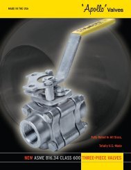
R 2 C h o k e<br />
www.taylorvalve.com<br />
23<br />
13<br />
11<br />
24<br />
8<br />
26<br />
17<br />
20<br />
21<br />
18<br />
19<br />
15<br />
27<br />
14<br />
12<br />
10<br />
9<br />
7<br />
16<br />
22<br />
4<br />
6<br />
15<br />
5<br />
25<br />
3<br />
2<br />
1<br />
ITEM NO QTY DESCRIPTION<br />
01 1 NOZZLE<br />
02 1 CAGE<br />
03 1 EXTERNAL SLEEVE<br />
04 1 BODY<br />
05 1 STEM<br />
06 1 BONNET<br />
07 1 STEM LOCK SCREW<br />
08 1 GREASE FITTING<br />
09 1 INDICATOR PIN<br />
10 1 INDICATOR SLEEVE<br />
11 1 ACTUATOR BRACKET<br />
12 1 ACTUATOR COUPLING<br />
13 2 THRUST BEARINGS<br />
14 1 SHAFT COLLAR<br />
15 1 STEM NUT<br />
16 6 HEX HD BOLT<br />
17 2 O-RING<br />
18 1 O-RING<br />
19 1 O-RING<br />
20 1 O-RING<br />
21 1 LOCK PIN<br />
22 1 DOWEL PIN<br />
23 1 GEARED HANDWHEEL<br />
24 4 HEX HD BOLT<br />
25 1 VENT FITTING<br />
26 2 PACKING<br />
27 4 ACTUATOR SPACER<br />
R2 Flow Curves<br />
Choke Cv<br />
40<br />
30<br />
20<br />
10<br />
80<br />
64<br />
48<br />
32<br />
Bean Size (64ths)<br />
R2 Control Cage<br />
API 10K<br />
External Sleeve<br />
0 10 20 30 40 50 60 70 80 90 100<br />
Percent of Full Open
R 3 C h o k e<br />
405.787.0145 USA<br />
23<br />
13<br />
11<br />
24<br />
8<br />
26<br />
17<br />
20<br />
21<br />
18<br />
19<br />
15<br />
27<br />
14<br />
12<br />
10<br />
9<br />
7<br />
16<br />
22<br />
4<br />
6<br />
15<br />
5<br />
25<br />
3<br />
2<br />
1<br />
ITEM NO QTY DESCRIPTION<br />
01 1 NOZZLE<br />
02 1 CAGE<br />
03 1 EXTERNAL SLEEVE<br />
04 1 BODY<br />
05 1 STEM<br />
06 1 BONNET<br />
07 1 STEM LOCK SCREW<br />
08 1 GREASE FITTING<br />
09 1 INDICATOR PIN<br />
10 1 INDICATOR SLEEVE<br />
11 1 ACTUATOR BRACKET<br />
12 1 ACTUATOR COUPLING<br />
13 2 THRUST BEARINGS<br />
14 1 SHAFT COLLAR<br />
15 1 STEM NUT<br />
16 8 HEX HD BOLT<br />
17 2 O-RING<br />
18 1 O-RING<br />
19 1 O-RING<br />
20 1 O-RING<br />
21 1 LOCK PIN<br />
22 1 DOWEL PIN<br />
23 1 GEARED HANDWHEEL<br />
24 4 HEX HD BOLT<br />
25 1 VENT FITTING<br />
26 2 PACKING<br />
27 4 ACTUATOR SPACER<br />
Choke Cv<br />
100<br />
80<br />
60<br />
40<br />
20<br />
R3 Flow Curves<br />
0 10 20 30 40 50 60 70 80 90 100<br />
Percent of Full Open<br />
112<br />
96<br />
80<br />
64<br />
48<br />
32<br />
Bean Size (64ths)<br />
R3 Control Cage<br />
API 5K<br />
External Sleeve
R 4 C h o k e<br />
www.taylorvalve.com<br />
23<br />
13<br />
11<br />
24<br />
8<br />
26<br />
17<br />
20<br />
21<br />
18<br />
19<br />
15<br />
27<br />
14<br />
12<br />
10<br />
9<br />
7<br />
16<br />
22<br />
4<br />
6<br />
15<br />
5<br />
25<br />
3<br />
2<br />
1<br />
ITEM NO QTY DESCRIPTION<br />
01 1 NOZZLE<br />
02 1 CAGE<br />
03 1 EXTERNAL SLEEVE<br />
04 1 BODY<br />
05 1 STEM<br />
06 1 BONNET<br />
07 1 STEM LOCK SCREW<br />
08 1 GREASE FITTING<br />
09 1 INDICATOR PIN<br />
10 1 INDICATOR SLEEVE<br />
11 1 ACTUATOR BRACKET<br />
12 1 ACTUATOR COUPLING<br />
13 2 THRUST BEARINGS<br />
14 1 SHAFT COLLAR<br />
15 1 STEM NUT<br />
16 12 HEX HD BOLT<br />
17 2 O-RING<br />
18 1 O-RING<br />
19 1 O-RING<br />
20 1 O-RING<br />
21 1 LOCK PIN<br />
22 1 DOWEL PIN<br />
23 1 GEARED HANDWHEEL<br />
24 4 HEX HD BOLT<br />
25 1 VENT FITTING<br />
26 2 PACKING<br />
27 4 ACTUATOR SPACER<br />
Choke Cv<br />
260<br />
220<br />
180<br />
140<br />
100<br />
60<br />
20<br />
R4 Flow Curves<br />
0 10 20 30 40 50 60 70 80 90 100<br />
Percent of Full Open<br />
192<br />
160<br />
128<br />
96<br />
64<br />
Bean Size (64ths)<br />
R4 Control Cage<br />
API 5K<br />
External Sleeve
R 6 C h o k e<br />
405.787.0145 USA<br />
23<br />
13<br />
11<br />
24<br />
8<br />
26<br />
17<br />
20<br />
21<br />
18<br />
19<br />
15<br />
27<br />
14<br />
12<br />
10<br />
9<br />
7<br />
16<br />
22<br />
4<br />
6<br />
15<br />
5<br />
25<br />
3<br />
2<br />
1<br />
ITEM NO QTY DESCRIPTION<br />
01 1 NOZZLE<br />
02 1 CAGE<br />
03 1 EXTERNAL SLEEVE<br />
04 1 BODY<br />
05 1 STEM<br />
06 1 BONNET<br />
07 1 STEM LOCK SCREW<br />
08 1 GREASE FITTING<br />
09 1 INDICATOR PIN<br />
10 1 INDICATOR SLEEVE<br />
11 1 ACTUATOR BRACKET<br />
12 1 ACTUATOR COUPLING<br />
13 2 THRUST BEARINGS<br />
14 1 SHAFT COLLAR<br />
15 1 STEM NUT<br />
16 12 HEX HD BOLT<br />
17 2 O-RING<br />
18 1 O-RING<br />
19 1 O-RING<br />
20 1 O-RING<br />
21 1 LOCK PIN<br />
22 1 DOWEL PIN<br />
23 1 GEARED HANDWHEEL<br />
24 4 HEX HD BOLT<br />
25 1 VENT FITTING<br />
26 2 PACKING<br />
27 4 ACTUATOR SPACER<br />
R6 Flow Curves<br />
500<br />
400<br />
288<br />
256<br />
R6 Control Cage<br />
API 5K<br />
External Sleeve<br />
Choke Cv<br />
300<br />
200<br />
100<br />
224<br />
192<br />
160<br />
128<br />
96<br />
Bean Size (64ths)<br />
0 10 20 30 40 50 60 70 80 90 100<br />
Percent of Full Open
R2 Choke / R3 Choke<br />
www.taylorvalve.com<br />
R2 Dimensions<br />
Inlet & Outlet Dimensions - In.(mm) Weight<br />
Connections* A B Lb Kg<br />
2”x 2” 150 RFF 7.00 (178) 92 42<br />
2”x 2” 300 RFF 7.25 (184) 96 44<br />
2”x 2” ANSI 600 RFF 7.62 (194) 100 45<br />
2”x 2” ANSI 600 RTJ 7.69 (195) 100 45<br />
2”x 2” ANSI 900 RF 8.75 (222) 128 58<br />
2”x 2” ANSI 900 RTJ 8.81 (223) 128 58<br />
2”x 2” ANSI 1500 RF 8.75 (222) 128 58<br />
2”x 2” ANSI 1500 RTJ 8.81 (223) 128 58<br />
2”x 2” ANSI 2500 RTJ 9.81 (249) 164 74<br />
2”x 3” BW x BW 4.50 (114) 4.50 (114) 96 44<br />
2”x 3” ANSI 900 RF 8.75 (222) 8.75 (222) 133 60<br />
2”x 3” ANSI 900 RTJ 8.81 (223) 8.81 (223) 133 60<br />
2”x 3” ANSI 1500 RF 8.75 (222) 8.75 (222) 152 69<br />
2”x 3” ANSI 1500 RTJ 8.81 (223) 9.94 (246) 152 69<br />
2”x 3” ANSI 2500 RTJ 9.81 (249) 11.50 (292) 216 98<br />
3”x 3” BW x BW 4.50 (114) 4.50 (114) 96 44<br />
3”x 3” ANSI 900 RF 8.75 (222) 138 63<br />
3”x 3” ANSI 900 RTJ 8.81 (223) 138 63<br />
3”x 3” ANSI 1500 RF 9.37 (238) 176 80<br />
3”x 3” ANSI 1500 RTJ 9.44 (239) 176 80<br />
3”x 3” ANSI 2500 RTJ 11.50 (292) 268 122<br />
2-1/16” x 2-1/16” API 3000 8.81 (223) 8.81 (223) 128 58<br />
2-1/16” x 2-1/16” API 5000 8.81 (223) 8.81 (223) 128 58<br />
2-1/16” x 3-1/8” API 3000 8.81 (223) 8.81 (223) 128 58<br />
2-1/16” x 3-1/8” API 5000 8.81 (223) 9.44 (239) 138 63<br />
3-1/8” x 3-1/8” API 3000 9.44 (239) 9.44 (239) 177 80<br />
* Other end connections are available. For more information contact Taylor <strong>Valve</strong>.<br />
Tolerances on A & B dimensions are ± 0.12” (± 3.05 mm).<br />
R3 Dimensions<br />
Inlet & Outlet Dimensions - In.(mm) Weight<br />
Connections* A B Lb Kg<br />
3”x 3” BW x BW 5.25 (133) 5.25 154 70<br />
3”x 3” ANSI 600 RF 8.75 (222) 190 86<br />
3”x 3” ANSI 600 RTJ 8.81 (223) 190 86<br />
3”x 3“ ANSI 900 RF 9.50 (241) 212 96<br />
3”x 3” ANSI 900 RTJ 9.56 (243) 212 96<br />
3”x 3” ANSI 1500 RF 10.12 (257) 10.12 212 96<br />
3”x 3” ANSI 1500 RTJ 10.19 (259) 250 114<br />
3”x 3” ANSI 2500 RTJ 12.25 (311) 342 155<br />
3”x 4” BW x BW 5.25 (133) 5.25 154 70<br />
3”x 4” ANSI 900 RF 9.50 (241) 10.00 (254) 234 106<br />
3”x 4” ANSI 900 RTJ 9.56 (242) 10.06 (255) 234 106<br />
3”x 4” ANSI 1500 RF 10.12 (257) 10.38 (263) 271 122<br />
3”x 4’’ ANSI 1500 RTJ 10.19 (258) 10.44 (265) 271 122<br />
3”x 4” ANSI 2500 RTJ 12.25 (311) 13.19 (335) 394 178<br />
4”x 4” ANSI BW x BW 5.25 (133) 5.25 154 70<br />
4”x 4” ANSI 900 RF 10.00 (254) 256 116<br />
4”x 4’ ANSI 900 RTJ 10.06 (256) 256 116<br />
4”x 4” ANSI 1500 RF 10.38 (263) 10.38 292 133<br />
4”x 4” ANSI 1500 RTJ 10.44 (265) 292 133<br />
4”x 4” ANSI 2500 RTJ 13.19 (335) 446 202<br />
3-1/8” x 3-1/8” API 3000 9.56 (242) 212 96<br />
3-1/8” x 3-1/8” API 5000 10.19 (258) 250 114<br />
3-1/8” x 4-1/16” API 3000 9.56 (242) 10.06 (255) 234 106<br />
3-1/8” x 4-1/16” API 5000 10.19 (258) 10.44 (265) 271 122<br />
4-1/16” x 4-1/16” API 3000 10.06 (255) 10.06 (255) 256 116<br />
4-1/16” x 4-1/16” API 5000 10.44 (265) 10.44 (265) 292 133<br />
* Other end connections are available. For more information contact Taylor <strong>Valve</strong>.<br />
Tolerances on A & B dimensions are ± 0.12” (± 3.05 mm).
R4 Choke / R6 Choke<br />
405.787.0145 USA<br />
R4 Dimensions<br />
Inlet & Outlet Dimensions - In.(mm) Weight<br />
Connections* A B Lb Kg<br />
4”x 4” ANSI 600 RF 10.75 (273) 451 205<br />
4”x 4” ANSI 600 RTJ 10.81 (275) 451 205<br />
4”x 4” ANSI 900 RF 11.25 (286) 479 217<br />
4”x 4” ANSI 900 RTJ 11.31 (287) 479 217<br />
4”x 4” ANSI 1500 RF 11.63 (295) 11.63 (295) 515 234<br />
4”x 4” ANSI 1500 RTJ 11.69 (297) 515 234<br />
4”x 4” ANSI 2500 RTJ 14.55 (367) 669 304<br />
4”x 6” ANSI 900 RF 11.25 (285) 12.25 538 243<br />
4”x 6” ANSI 900 RTJ 11.31 (287) 12.31 (312) 538 243<br />
4”x 6” ANSI 1500 RF 11.63 (295) 13.50 (342) 610 276<br />
4”x 6” ANSI 1500 RTJ 16.69 (296) 13.62 (345) 610 276<br />
4”x 6” ANSI 2500 RTJ 14.44 (355) 17.75 (450) 901 408<br />
6”x 6” ANSI 900 RF 12.25 (311) 597 271<br />
6”x 6” ANSI 900 RTJ 12.31 (313) 597 271<br />
6”x 6” ANSI 1500 RF 13.50 (342) 13.50 597 271<br />
6”x 6” ANSI 1500 RTJ 13.62 (346) 705 320<br />
6”x 6” ANSI 2500 RTJ 17.75 (451) 1133 514<br />
4-1/16” x 4-1/16” API 3000 11.31 (287) 11.31 (287) 479 217<br />
4-1/16” x 4-1/16” API 5000 11.69 (296) 11.69 (269) 515 234<br />
4-1/16” x 7-1/16” API 3000 11.69 (296) 12.31 (312) 538 243<br />
4-1/16” x 7-1/16” API 5000 11.69 (296) 13.63 (346) 610 276<br />
7-1/16” x 7-1/16” API 3000 12.31 (312) 12.31 (312) 597 271<br />
7-1/16” x 7-1/16” API 5000 13.63 (346) 13.63 (346) 705 320<br />
R6 Dimensions<br />
Inlet & Outlet Dimensions - In.(mm) Weight<br />
Connections* A B Lb Kg<br />
6” x 6” ANSI 600 RF 14.38 (365) 929 422<br />
6” x 6” ANSI 600 RTJ 14.44 (368) 929 422<br />
6” x 6” ANSI 900 RF 15.25 (387) 1003 455<br />
6” x 6” ANSI 900 RTJ 15.31 (389) 1003 455<br />
6” x 6” ANSI 1500 RF 16.50 (419) 1111 504<br />
6” x 6” ANSI 1500 RTJ 16.62 (422) 1111 504<br />
6” x 6” ANSI 2500 RTJ 20.75 (527) 1539 699<br />
6” x 8” ANSI 900 RF 15.25 (387) 16.12 (409) 1080 489<br />
6” x 8” ANSI 900 RTJ 15.31 (388) 16.12 (409) 1080 489<br />
6” x 8” ANSI 1500 RF 16.62 (422) 18.31 (465) 1220 553<br />
6” x 8” ANSl 1500 RTJ 16.62 (422) 18.31 (465) 1220 553<br />
6” x 8” ANSI 2500 RTJ 20.75 (527) 22.56 (573) 1737 787<br />
8” x 8” ANSI 900 RF 16.12 (410) 1157 525<br />
8” x 8” ANSI 900 RTJ 16.12 (410) 1157 525<br />
8” x 8” ANSI 1500 RF 18.31 (465) 1329 603<br />
8” x 8” ANSI 1500 RTJ 18.31 (465) 1329 603<br />
8” x 8” ANSI 2500 RTJ 22.56 (573) 1935 878<br />
7-1/16” x 7-1/16” API 3000 15.31 (388) 1157 525<br />
7-1/16” x 7-1/16” API 5000 16.63 (422) 1329 603<br />
7-1/16” x 9” API 3000 15.31 (388) 16.19 (411) 1411 639<br />
7-1/16” x 9” API 5000 16.63 (422) 18.31 (465) 1463 663<br />
9” x 9” API 3000 16.19 (411) 16.19 (411) 1510 684<br />
9” x 9” API 5000 18.31 (465) 18.31 (465) 1532 694<br />
* Other end connections are available. For more information contact Taylor <strong>Valve</strong>.<br />
Tolerances on A & B dimensions are ± 0.12” (± 3.05 mm).<br />
.<br />
* Other end connections are available. For more information contact Taylor <strong>Valve</strong><br />
Tolerances on A & B dimensions are ± 0.12” (± 3.05 mm).
Heater Choke<br />
www.taylorvalve.com<br />
MODEL R2 HC Heater Choke<br />
The Taylor 10,000 psi cwp Heater Choke is<br />
among a very select group in its class. The<br />
R2 HC is subject to the severe demands of<br />
production operation, designed with<br />
features to make it one of the most rugged<br />
and durable special application chokes. The<br />
MOC trim offers the field proven<br />
advantages of fluid stream impingement,<br />
containing the cavitation within the heavy<br />
walled tungsten carbide cage. This configuration<br />
delivers a clean, non-destructive<br />
flow into the expansion coils that dramatically<br />
reduces the incidence of cut out in the<br />
heater tubes.<br />
The External Sleeve is fully guided on the<br />
cage to eliminate stem imbalance,<br />
minimize vibration and the resulting noise<br />
and wear. The stem seal is a spring-loaded,<br />
pressure energized TFE compound that is<br />
rated from -75° F to +500° F, making it<br />
highly resistant to typical severe service<br />
media associated with the drilling and<br />
production industries. The tri-seat shut-in<br />
seal is designed to provide a long-term<br />
positive shutoff. The seat surfaces are not<br />
directly exposed to the high velocity flow of<br />
the orifice areas. Adjustable chokes can be<br />
converted to positive and vice-versa.<br />
Consult with Taylor sales personnel for<br />
other options.
Taylor <strong>Valve</strong> Technology, Inc.<br />
405.787.0145 USA<br />
NOTES:
CONTROL VALVE DATA SHEET<br />
8300 Southwest 8th Street • Oklahoma City, OK 73128<br />
405.787.0145 USA • fax 405.789.8198 USA • fwww.taylorvalve.com<br />
COPYRIGHT: © 2004, Taylor <strong>Valve</strong> Technology, Inc. All rights reserved.