- Page 1 and 2: Cooling SPECIFIER’S GUIDE EQUIPME
- Page 3 and 4: Table of Contents QUICK REFERENCE C
- Page 5 and 6: Quick Reference Side Mount Roof Mou
- Page 7 and 8: Intro Page Chapter Contents Selecti
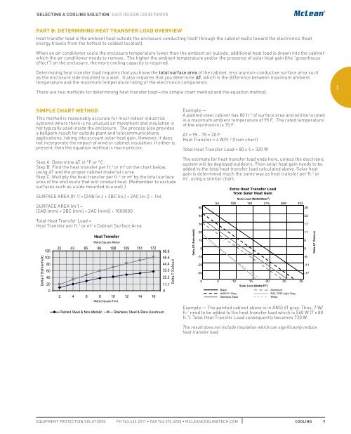
- Page 9 and 10: Selecting A Cooling Solution oVERVI
- Page 11: Selecting A Cooling Solution Sealed
- Page 15 and 16: Selecting A Cooling Solution Sealed
- Page 17 and 18: Selecting A Cooling Solution FRESH
- Page 19 and 20: Selecting A Cooling Solution FRESH
- Page 21 and 22: Selecting A Cooling Solution FRESH
- Page 23 and 24: Selecting A Cooling Solution FRESH
- Page 25 and 26: Intro Page Chapter Contents Technic
- Page 27 and 28: Technical InfoRMATion UL and IP DEF
- Page 29 and 30: Technical InfoRMATion UL and IP DEF
- Page 31 and 32: Intro Page Chapter Contents Sealed
- Page 33 and 34: Sealed EncloSURE Cooling aIR ConDIT
- Page 35 and 36: Sealed EncloSURE Cooling aIR ConDIT
- Page 37 and 38: Sealed EncloSURE Cooling aIR ConDIT
- Page 39 and 40: Sealed EncloSURE Cooling aIR ConDIT
- Page 41 and 42: Sealed EncloSURE Cooling aIR ConDIT
- Page 43 and 44: Sealed EncloSURE Cooling aIR ConDIT
- Page 45 and 46: Sealed EncloSURE Cooling aIR ConDIT
- Page 47 and 48: Sealed EncloSURE Cooling aIR ConDIT
- Page 49 and 50: Sealed EncloSURE Cooling aIR ConDIT
- Page 51 and 52: Sealed EncloSURE Cooling aIR ConDIT
- Page 53 and 54: Sealed EncloSURE Cooling aIR ConDIT
- Page 55 and 56: Sealed EncloSURE Cooling aIR ConDIT
- Page 57 and 58: Sealed EncloSURE Cooling aIR ConDIT
- Page 59 and 60: Sealed EncloSURE Cooling aIR ConDIT
- Page 61 and 62: Sealed EncloSURE Cooling aIR ConDIT
- Page 63 and 64:
Sealed EncloSURE Cooling aIR ConDIT
- Page 65 and 66:
Sealed EncloSURE Cooling aIR ConDIT
- Page 67 and 68:
Sealed EncloSURE Cooling aIR ConDIT
- Page 69 and 70:
Sealed EncloSURE Cooling aIR ConDIT
- Page 71 and 72:
Sealed EncloSURE Cooling aIR ConDIT
- Page 73 and 74:
Sealed EncloSURE Cooling aIR ConDIT
- Page 75 and 76:
Sealed EncloSURE Cooling aIR ConDIT
- Page 77 and 78:
Sealed EncloSURE Cooling aIR ConDIT
- Page 79 and 80:
Sealed EncloSURE Cooling aIR ConDIT
- Page 81 and 82:
Sealed EncloSURE Cooling aIR ConDIT
- Page 83 and 84:
Sealed EncloSURE Cooling aIR ConDIT
- Page 85 and 86:
Sealed EncloSURE Cooling aIR ConDIT
- Page 87 and 88:
Sealed EncloSURE Cooling aIR ConDIT
- Page 89 and 90:
Sealed EncloSURE Cooling aIR ConDIT
- Page 91 and 92:
Sealed EncloSURE Cooling aIR ConDIT
- Page 93 and 94:
Sealed EncloSURE Cooling aIR ConDIT
- Page 95 and 96:
Sealed EncloSURE Cooling aIR ConDIT
- Page 97 and 98:
Sealed EncloSURE Cooling aIR ConDIT
- Page 99 and 100:
Sealed EncloSURE Cooling aIR ConDIT
- Page 101 and 102:
Sealed EncloSURE Cooling aIR ConDIT
- Page 103 and 104:
Sealed EncloSURE Cooling aIR ConDIT
- Page 105 and 106:
Sealed EncloSURE Cooling aIR ConDIT
- Page 107 and 108:
Sealed EncloSURE Cooling aIR ConDIT
- Page 109 and 110:
Sealed EncloSURE Cooling aIR ConDIT
- Page 111 and 112:
Sealed EncloSURE Cooling aIR ConDIT
- Page 113 and 114:
Sealed EncloSURE Cooling aIR ConDIT
- Page 115 and 116:
Sealed EncloSURE Cooling aIR ConDIT
- Page 117 and 118:
Sealed EncloSURE Cooling aIR ConDIT
- Page 119 and 120:
Sealed EncloSURE Cooling aIR ConDIT
- Page 121 and 122:
Sealed EncloSURE Cooling aIR ConDIT
- Page 123 and 124:
Sealed EncloSURE Cooling aIR ConDIT
- Page 125 and 126:
Sealed EncloSURE Cooling aIR ConDIT
- Page 127 and 128:
Sealed EncloSURE Cooling aIR ConDIT
- Page 129 and 130:
Sealed EncloSURE Cooling aIR ConDIT
- Page 131 and 132:
Sealed EncloSURE Cooling aIR ConDIT
- Page 133 and 134:
Sealed EncloSURE Cooling aIR ConDIT
- Page 135 and 136:
Sealed EncloSURE Cooling aIR ConDIT
- Page 137 and 138:
Sealed EncloSURE Cooling aIR ConDIT
- Page 139 and 140:
Sealed EncloSURE Cooling aIR ConDIT
- Page 141 and 142:
Sealed EncloSURE Cooling aIR ConDIT
- Page 143 and 144:
Sealed EncloSURE Cooling aIR ConDIT
- Page 145 and 146:
Sealed EncloSURE Cooling aIR ConDIT
- Page 147 and 148:
Sealed EncloSURE Cooling aIR ConDIT
- Page 149 and 150:
Sealed EncloSURE Cooling Heat EXCHa
- Page 151 and 152:
Sealed EncloSURE Cooling Heat EXCHa
- Page 153 and 154:
Sealed EncloSURE Cooling Heat EXCHa
- Page 155 and 156:
Sealed EncloSURE Cooling Heat EXCHa
- Page 157 and 158:
Sealed EncloSURE Cooling Heat EXCHa
- Page 159 and 160:
Sealed EncloSURE Cooling Heat EXCHa
- Page 161 and 162:
Sealed EncloSURE Cooling Heat EXCHa
- Page 163 and 164:
Sealed EncloSURE Cooling Heat EXCHa
- Page 165 and 166:
Sealed EncloSURE Cooling Heat EXCHa
- Page 167 and 168:
Sealed EncloSURE Cooling Heat EXCHa
- Page 169 and 170:
Sealed EncloSURE Cooling Heat EXCHa
- Page 171 and 172:
Sealed EncloSURE Cooling Heat EXCHa
- Page 173 and 174:
Sealed EncloSURE Cooling Heat EXCHa
- Page 175 and 176:
Sealed EncloSURE Cooling Heat EXCHa
- Page 177 and 178:
Sealed EncloSURE Cooling Heat EXCHa
- Page 179 and 180:
Sealed EncloSURE Cooling Heat EXCHa
- Page 181 and 182:
Sealed EncloSURE Cooling Heat EXCHa
- Page 183 and 184:
Sealed EncloSURE Cooling Heat EXCHa
- Page 185 and 186:
Sealed EncloSURE Cooling Heat EXCHa
- Page 187 and 188:
Sealed EncloSURE Cooling Heat EXCHa
- Page 189 and 190:
Sealed EncloSURE Cooling THERMoelEC
- Page 191 and 192:
Sealed EncloSURE Cooling THERMoelEC
- Page 193 and 194:
Sealed EncloSURE Cooling THERMoelEC
- Page 195 and 196:
Sealed EncloSURE Cooling THERMoelEC
- Page 197 and 198:
Sealed EncloSURE Cooling THERMoelEC
- Page 199 and 200:
Sealed EncloSURE Cooling VoRTEX Coo
- Page 201 and 202:
Sealed EncloSURE Cooling VoRTEX Coo
- Page 203 and 204:
Intro Page FAN TRAYS Fan Trays deli
- Page 205 and 206:
Fresh Air EncloSURE Cooling DIRECT
- Page 207 and 208:
Fresh Air EncloSURE Cooling DIRECT
- Page 209 and 210:
Fresh Air EncloSURE Cooling DIRECT
- Page 211 and 212:
Fresh Air EncloSURE Cooling FilTER
- Page 213 and 214:
Fresh Air EncloSURE Cooling FilTER
- Page 215 and 216:
Fresh Air EncloSURE Cooling FilTER
- Page 217 and 218:
Fresh Air EncloSURE Cooling FilTER
- Page 219 and 220:
Fresh Air EncloSURE Cooling FilTER
- Page 221 and 222:
Fresh Air EncloSURE Cooling FilTER
- Page 223 and 224:
Fresh Air EncloSURE Cooling FilTER
- Page 225 and 226:
Fresh Air EncloSURE Cooling FilTER
- Page 227 and 228:
Fresh Air EncloSURE Cooling FilTER
- Page 229 and 230:
Fresh Air EncloSURE Cooling FilTER
- Page 231 and 232:
Fresh Air EncloSURE Cooling FilTER
- Page 233 and 234:
Fresh Air EncloSURE Cooling FilTER
- Page 235 and 236:
Fresh Air EncloSURE Cooling FilTER
- Page 237 and 238:
Fresh Air EncloSURE Cooling FilTER
- Page 239 and 240:
Fresh Air EncloSURE Cooling FilTER
- Page 241 and 242:
Fresh Air EncloSURE Cooling FilTER
- Page 243 and 244:
Fresh Air EncloSURE Cooling FilTER
- Page 245 and 246:
Fresh Air EncloSURE Cooling FilTER
- Page 247 and 248:
Fresh Air EncloSURE Cooling FilTER
- Page 249 and 250:
Fresh Air EncloSURE Cooling FilTER
- Page 251 and 252:
Fresh Air EncloSURE Cooling aXIal F
- Page 253 and 254:
Fresh Air EncloSURE Cooling aXIal F
- Page 255 and 256:
Fresh Air EncloSURE Cooling aXIal F
- Page 257 and 258:
Fresh Air EncloSURE Cooling Fan Tra
- Page 259 and 260:
Fresh Air EncloSURE Cooling Fan Tra
- Page 261 and 262:
Fresh Air EncloSURE Cooling PackaGE
- Page 263 and 264:
Fresh Air EncloSURE Cooling PackaGE
- Page 265 and 266:
Fresh Air EncloSURE Cooling PackaGE
- Page 267 and 268:
Fresh Air EncloSURE Cooling aIR MoV
- Page 269 and 270:
Fresh Air EncloSURE Cooling aIR MoV
- Page 271 and 272:
Fresh Air EncloSURE Cooling BloWERS
- Page 273 and 274:
Fresh Air EncloSURE Cooling BloWERS
- Page 275 and 276:
Fresh Air EncloSURE Cooling Motoriz
- Page 277 and 278:
Fresh Air EncloSURE Cooling Motoriz
- Page 279 and 280:
Fresh Air EncloSURE Cooling Motoriz
- Page 281 and 282:
Fresh Air EncloSURE Cooling Motoriz
- Page 283 and 284:
Fresh Air EncloSURE Cooling Motoriz
- Page 285 and 286:
Fresh Air EncloSURE Cooling Motoriz
- Page 287 and 288:
Fresh Air EncloSURE Cooling Motoriz
- Page 289 and 290:
Fresh Air EncloSURE Cooling Motoriz
- Page 291 and 292:
Fresh Air EncloSURE Cooling aCCESSo
- Page 293 and 294:
Fresh Air EncloSURE Cooling aCCESSo
- Page 295 and 296:
Intro Page Chapter Contents Accesso
- Page 297 and 298:
Accessories Condensation ManaGEMEnt
- Page 299 and 300:
Accessories Condensation ManaGEMEnt
- Page 301 and 302:
Accessories EncloSURE HeaTERS Semic
- Page 303 and 304:
Accessories EncloSURE HeaTERS Elect
- Page 305 and 306:
Accessories EncloSURE HeaTERS 5 EQU
- Page 307 and 308:
Accessories EncloSURE HeaTERS Hazar
- Page 309 and 310:
Accessories ControllERS Dual Thermo
- Page 311 and 312:
Accessories ControllERS Mechanical
- Page 313 and 314:
Accessories ControllERS Panel-Mount
- Page 315 and 316:
Accessories ControllERS Notes 5 EQU
- Page 317 and 318:
Accessories PRESSURE CoMPEnsation P
- Page 319 and 320:
6 Catalog nUMBER Index PH FAX MCLEA
- Page 321 and 322:
6 Catalog nUMBER Index PH FAX MCLEA
- Page 323 and 324:
6 Catalog nUMBER Index PH FAX MCLEA
- Page 325 and 326:
Notes
- Page 327:
SKARPNÄCK HEMEL HEMPSTEAD DZIERŻO