Bulletin M 0104 UK Rev 4
Bulletin M 0104 UK Rev. 4 - Commercial Fuel Solutions Ltd
Bulletin M 0104 UK Rev. 4 - Commercial Fuel Solutions Ltd

Create successful ePaper yourself
Turn your PDF publications into a flip-book with our unique Google optimized e-Paper software.
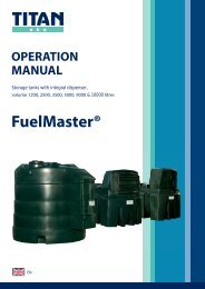
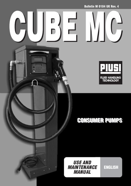
<strong>Bulletin</strong> M <strong>0104</strong> <strong>UK</strong> <strong>Rev</strong>. 4
2<br />
ENGLISH ................................................................... pag. 27
E<br />
DECLARATION OF CONFORMITY<br />
The undersigned, representing the following manufacturer<br />
PIUSI S.p.A.<br />
46029 SUZZARA (MANTOVA) ITALY<br />
hereby CERTIFIES that the equipment described below:<br />
Description:<br />
Model:<br />
DIESEL FUEL DISPENSER<br />
CUBE MC<br />
Complies with the following directives:<br />
- 89/336 EEC (Electromagnetic Compatibility Directive EMC) and subsequent amendments<br />
- 73/23 EEC (Low-Voltage Directive) and subsequent amendments<br />
This is in conformity with the following International Standards (and their subsequent amendments):<br />
EN 292-1<br />
EN 292-2<br />
EN 294<br />
Safety of Machinery - Basic Concepts, General Principles for Design - Terminology,<br />
Basic Methodology.<br />
Safety of Machinery - Basic Concepts, General Principles for Design - Specifications<br />
and Technical Principles.<br />
Safety of Machinery - Safe Distances to Prevent the Operator's Upper Limbs from<br />
Reaching Dangerous Areas.<br />
EN 61000-6-1<br />
EN 61000-6-3<br />
Electromagnetic compatibility - Generic standards - Immunity for residential,<br />
commercial and light-industrial environments.<br />
Electro-Magnetic Compatibility - Generic Emission Standards - Residential,<br />
Commercial and Light Industrial Environments.<br />
EN 60204-1<br />
EN 60335-1<br />
Safety of Machinery - Electric Equipment of Machines - General Rules.<br />
Household and similar appliances - Safety - General requirements.<br />
EN 60335-2-41/A1 Household and similar appliances - Safety - Particular requirements for pumps.<br />
EN 60335-2-75 Household and similar appliances - Safety - Particular requirements for commercial<br />
dispensing appliances and vending machines (electrical or gas powered).<br />
And is in conformity with the following Italian National Decrees:<br />
MD 31.07.1934 -Heading 1 No. XVII<br />
Approval of the applicable Safety Rules for the storing, use and transport of mineral oils.<br />
Last two figures of the year of CE marking: 04<br />
Suzzara, 01.01.04<br />
OTTO VARINI, Chairman<br />
28
E<br />
B<br />
FIRST AID RULES<br />
Persons who have ingested toxic liquids: whenever fuel has been swallowed, do<br />
not induce vomiting, but have the injured person drink large quantities of milk or<br />
water.<br />
Persons who have suffered electric shock: disconnect the power source, or use<br />
a dry insulator to protect yourself while you move the injured person away from any<br />
electrical conductor. Avoid touching the injured person with your bare hands until<br />
he is far away from any conductor. Immediately call for help from qualified and<br />
trained personnel.<br />
IN ALL CASES, SEEK MEDICAL ATTENTION IMMEDIATELY<br />
C<br />
GENERAL INFORMATION<br />
CUBE MC dispensers are appliances designed for the private distribution of diesel fuel for<br />
motor transport. All the models of the series have the same sturdy metal structure and selfpriming<br />
type pumps. Reliability of the pumping units, precise measuring of the dispensed<br />
product and Control System efficiency are the strong points of CUBE MC.<br />
This manual refers to CUBE MC models only.<br />
D<br />
SAFETY INSTRUCTIONS<br />
All the CUBE MC models have been designed and built according to applicable EC directives<br />
relating to essential safety and health requirements.<br />
Page 28 of this manual shows a copy of the manufacturer's DECLARATION OF CONFORMITY.<br />
D1<br />
SAFETY RULES<br />
Protective gloves. Prolonged contact with hydrocarbons can cause skin irritation:<br />
when dispensing fuel always use PVC gloves conforming to the standard EN 388<br />
cat.2.<br />
Permitted uses. The unit must always be used for the purpose intended. Follow the<br />
instructions listed in the chapter Instructions for Use.<br />
Overheating. To prevent overheating, make sure that the pump of the dispenser<br />
stops whenever fuel has not been dispensed for more than 2 minutes.<br />
Smoking prohibited. When operating the dispenser and in particular during<br />
refuelling, do not smoke and do not use open flame.<br />
Electrical precautions. There are dangerously high voltages inside the unit.<br />
Only qualified and authorized technical personnel are allowed to open the<br />
dispenser.<br />
Service. Service of the dispenser must be performed by qualified personnel.<br />
29
E<br />
D2<br />
TRANSPORT, HANDLING AND UNPACKING<br />
CUBE MC is shipped inside stackable<br />
cardboard packaging.<br />
DIMENSIONS OF PACKAGING:<br />
h=480 mm /<br />
L=380 mm /<br />
D=380 mm<br />
TOTAL WEIGHT:<br />
CUBE 70 MC = 26.5 kg<br />
WEIGHT OF<br />
PACKAGING: 1.8 kg<br />
When the machine is not used, whether it is packed or unpacked, it must be stored in a place<br />
protected from the weather (rain, damp, sun, etc.) and from dust. To remove the cardboard<br />
packaging, use a pair of scissors or cutters, being careful not to damage the appliance. Fully open<br />
the packaging and take out the CUBE MC so that it can be taken to the place of final installation.<br />
Once the packaging has been removed, the station must always be kept in vertical position.<br />
Packaging parts (cardboard, wood, cellophane, etc...) must be placed in specific containers and not<br />
left lying around or within reach of children, as these represent a potential risk hazard. They must be<br />
disposed of according to the regulations applicable in the country of use.<br />
Check the integrity of the machine by making sure the shipped parts are not damaged in any<br />
way that could affect safety and operation. In case of any doubts, do not start the appliance<br />
but contact the manufacturer's after-sales service.<br />
After unpacking, proceed to assemble the CUBE MC, as shown below:<br />
- Fit the hose support hook (PHOTO No. 1)<br />
- Fit the equaliser operating lever (PHOTO No. 2)<br />
- Apply thread sealer at the points shown in the photo, before proceeding with final assembly.<br />
(PHOTO No. 3)<br />
PHOTO No. 1 PHOTO No. 2 PHOTO No. 3<br />
30
E<br />
D3<br />
DISPOSAL<br />
In the event that the dispenser is to be demolished, the parts of which it is composed must be sent<br />
to companies that specialize in the disposal and recycling of industrial refuse and, in particular:<br />
PACKING MATERIAL DISPOSAL:<br />
The packing material consists of biodegradable cardboard that can be delivered to<br />
companies that normally recover cellulose.<br />
METAL PARTS DISPOSAL:<br />
The metal parts, both painted and stainless steel are normally recoverable by companies<br />
specialized in scrapping metal.<br />
DISPOSAL OF ELECTRONIC BOARDS:<br />
The electronic boards must necessarily be disposed of through companies specialised in the<br />
disposal of electronic components.<br />
MISCELLANEOUS PARTS DISPOSAL:<br />
Additional parts making up the dispenser, such as tubes, rubber gaskets, plastic parts and wiring<br />
harness, must be delivered to companies specialized in the disposal of industrial refuse.<br />
E<br />
USING AND LOOKING AFTER MANUALS<br />
This manual is common to all CUBE MC models and illustrates the main characteristics of the<br />
various models, providing information on:<br />
- electrical and mechanical installation<br />
- first start up operations<br />
- daily use<br />
This manual DOES NOT cover other aspects such as:<br />
- configuration and operation of the Control system<br />
For these aspects, refer to the specific manuals which accompany each station model.<br />
ATTENTION<br />
The list in paragraph F1 indicates the number of the manual where the component is<br />
described in detail (pump, meter, control system, etc.)<br />
For the installer's convenience, all supplied manuals are grouped together in an envelope.<br />
This collection of manuals is an integral and essential part of the product and, as provided by<br />
EEC directive 89/392, must be given to the persons in charge of using and servicing the<br />
machine, to ensure fulfilment of the provisions relating to training/information referred to in<br />
EEC directive 89/391.<br />
Carefully read the instructions contained in these manuals, as these are most important for<br />
installation safety, operation and maintenance.<br />
The manufacturer disclaims all liability for injury to persons or damage to things, or the<br />
machine, in the event of this being used in a way different to that indicated in the instructions.<br />
Look after this manual carefully in a place protected from damp, heat, dust, oils, greases, etc.,<br />
as it will be useful for future reference and consultation. Do not remove, tear or amend any<br />
parts of the manual for any reason. In case of loss or damage, ask the manufacturer for a<br />
copy, quoting the manual code.<br />
This manual must always remain with the machine; in the event of the machine being sold, it<br />
must be given to the new user.<br />
ATTENTION<br />
The company reserves the right to change CUBE MC features and specifications at any time.<br />
31
E<br />
E1<br />
LIST OF SUPPLIED MANUALS<br />
Below is a list of all the manuals, besides this one, to be provided together with the CUBE MC:<br />
- M0042 Panther 72 pump manual<br />
- M0046 K600 meter manual<br />
- M0103 CUBE MC control system manual<br />
- M0105 Cube MC software manual<br />
E2<br />
IDENTIFICATION PLATE<br />
The cube MC stations feature an<br />
identification plate showing:<br />
- Model<br />
- Serial number / Year of manufacture<br />
- Technical specifications<br />
- CE mark<br />
PRODUCT<br />
NAME<br />
PRODUCT<br />
CODE<br />
MANUFACTURER<br />
TECHNICAL<br />
SPECIFICATIONS<br />
SERIAL<br />
NUMBER<br />
PRODUCTION<br />
YEAR<br />
"CE" MARK<br />
ATTENTION<br />
Before installing, always make sure the dispenser model is correct and suitable for the<br />
available power supply (voltage/frequency).<br />
32
E<br />
F<br />
DESCRIPTION OF MAIN PARTS<br />
CUBE MC dispensers are designed for the transfer of diesel fuel<br />
for private use. Characterized by maximum safety and simplicity<br />
of use, CUBE dispensers are dependable, high-performance<br />
equipment that is quickly installed and ready for use.<br />
Equipment and features are:<br />
1 Blade type rotating self-priming pump with incorporated<br />
bypass valve.<br />
2 Motor with degree of protection IP55 and heat protection,<br />
230 V AC single phase.<br />
3 Four meters of anti-static rubber tube for fuel.<br />
4 Automatic type dispenser nozzle with ON/OFF switch<br />
integrated in the nozzle support.<br />
5 Steel body with anti-corrosion treatment and paint finish.<br />
6 Control system.<br />
7 Meter<br />
6<br />
ROOF<br />
INSPECTION<br />
PANEL<br />
4<br />
5<br />
FRONT<br />
F2<br />
PUMP UNIT<br />
Unit with blade type self-priming electric pump,<br />
featuring bypass valve. Such a valve allows<br />
functioning for brief periods of time even with<br />
the dispensing nozzle closed.<br />
The motor, which is directly coupled to the<br />
pump body, is asynchronous, of the closed<br />
type (degree of protection IP 55 according to<br />
EN 60034-5-86 standard) self-ventilated, single<br />
phase. For further details, refer to the relevant<br />
manuals indicated in the summary table of<br />
paragraph E1.<br />
3<br />
7<br />
1<br />
2<br />
F3<br />
PULSER METER<br />
The K600/3 Pulser meter features a measurement system with high-precision oval gears<br />
designed for accurate fuel metering. These have a sturdy drawn aluminium structure and are<br />
complete with suction filter. They are easy to service and reliable. For further details, see the<br />
manual indicated on the summary table of paragraph E1.<br />
F4<br />
CONTROL SYSTEM<br />
The electronic control system -MC- ensures the dispenser can only be used by authorised<br />
personnel. All the data relating to each dispensing operation are stored and can be transferred<br />
to a PC (optional).<br />
For further details, see the manual indicated on the summary table of paragraph E1.<br />
F5<br />
NOZZLE<br />
The nozzle supplied with CUBE MC is of automatic type; it is fitted with a shut-off device for full tank.<br />
F6<br />
DISPLAY UNIT COVER<br />
To ensure adequate protection and the correct visibility of the CUBE MC display units,<br />
including in very strong light conditions, a pull-out display unit cover has been integrated in<br />
the structure. This can be lowered in case of need. In very strong light conditions, we<br />
advise always keeping the display cover lowered when not in use.<br />
33
E<br />
G<br />
TECHNICAL SPECIFICATIONS<br />
MODEL POWER VOLTAGE ABSORPTION (A) POWER (W) FLOW RATE (l/min)<br />
CUBE MC 230 V / 50 Hz 4.2 900<br />
70<br />
G1<br />
PERMITTED USES<br />
Transfer of diesel fuel with a viscosity from 2 to 5.35 cSt at 37.8° C and PM flash point > 55° C.<br />
G2<br />
USES NOT PERMITTED<br />
The transfer of fluids with different characteristics than those indicated above is not allowed.<br />
In particular:<br />
- Gasoline, solvents and inflammable liquids with PM < 55° C (danger of fire/explosion).<br />
- Liquid food products (contamination of the same).<br />
- Water (pump oxidation).<br />
- Corrosive chemical products (pump corrosion).<br />
- Liquids with viscosity >20 cSt (motor overload).<br />
G3<br />
ABSORBED POWER<br />
The CUBE MC stations must be powered by a power line with the same RATED VOLTAGE /<br />
FREQUENCY as that indicated on the IDENTIFICATION PLATE.<br />
The maximum acceptable variations from the electrical parameters are:<br />
- VOLTAGE +/- 5%<br />
- FREQUENCY +/- 2%<br />
The IDENTIFICATION PLATE shows maximum ABSORBED POWER (in Ampères), with<br />
respect to which, the power protection appliances required by applicable standards (not<br />
supplied with the station) must be sized.<br />
The maximum absorbed power refers to intended-use operation - DISPENSING OF DIESEL<br />
FUEL - with power supply within the above-mentioned limits.<br />
G4<br />
HYDRAULIC PERFORMANCE<br />
When correctly installed and powered, and used for the purpose for which they were designed<br />
- DISPENSING OF DIESEL FUEL - the CUBE MC stations perform as follows:<br />
- Model CUBE MC: FLOW RATE MAX 70 litres/minute<br />
The installed pumps ensure CONTINUOUS operation of the stations.<br />
G5<br />
CONTROL SYSTEM PERFORMANCE<br />
The performance of the MC control system is detailed in the M0103 manual supplied together<br />
with the CUBE MC.<br />
G6<br />
METERING ACCURACY<br />
Thanks to the PULSER K600 METER and to the MC control system which ensures precise<br />
CALIBRATION, the CUBE MC stations provide the following performance:<br />
34<br />
ACCURACY: +/- 0,5%<br />
(after calibration, for flow rates above 5 litres/minute).
E<br />
H<br />
INSTALLATION<br />
H1<br />
GENERAL<br />
CUBE MC can be installed outside. Nevertheless, it is advisable to locate it under the shelter<br />
of a roof to ensure the dispenser's longevity and provide greater comfort during refuelling in<br />
the event of bad weather. The installation of the dispenser must be carried out by skilled<br />
personnel and performed according to the instructions provided in this chapter.<br />
Whenever CUBE MC is not installed under cover, a "display cover" is provided to protected the<br />
display and keyboard.<br />
ATTENTION<br />
The motors are not of an anti-explosive type. DO NOT install CUBE MC in places where<br />
there is risk of explosion.<br />
The CUBE MC stations can be connected both to tanks above ground and tanks under ground.<br />
H2<br />
STATION POSITIONING<br />
The positioning of the SELF SERVICE must be such that it is possible to:<br />
- Easily remove the panels to access the inner components when necessary.<br />
- Observe the distances and maximum differences in level between the station and the tank.<br />
- Securely fasten the casing to the ground on a horizontal surface.<br />
Station positioning determines the following parameters, which distinguish each installation:<br />
Hp: Priming height<br />
Ls: Total length of the suction pipe - from the foot valve to the station<br />
(expressed in metres)<br />
To ensure correct station operation, the following limitations must always be kept to:<br />
Hp max: not over 3 metres<br />
LS max: not over 15 metres<br />
H3<br />
MECHANICAL INSTALLATION<br />
Before starting installation, make sure no packaging materials are trapped in the pipes.<br />
Prepare suitable stilts or fixing brackets depending on the fixing position of the CUBE MC.<br />
The tube coming from the tank must be aligned to the threaded inlet of the pump filter which<br />
is located under the CUBE MC.<br />
TANK ABOVE<br />
GROUND<br />
TANK UNDER<br />
GROUND<br />
35
E<br />
H4<br />
HYDRAULIC CONNECTIONS<br />
SUCTION LINE<br />
The diameter of the "Ds" suction line must be selected according to the station model and the<br />
position of the station with respect to the tank.<br />
With reference to the "Hp" and "Ls" values indicated at point H2, the following MINIMUM<br />
DIAMETERS of the suction pipe must always be ensured.<br />
H4.1 MAXIMUM LENGTH OF THE SUCTION PIPES<br />
The maximum length of the tubing, the diameter of the tubing, the difference in height, are<br />
parameters that are tightly linked to creating suction conditions. The latter must not be such<br />
as to create backpressure greater than 0.6 bar. It follows as a consequence that, after<br />
respecting the minimum diameter of the tubing specified in the "Recommendations and<br />
Warnings" below, the length of the tubing decreases as the difference in height that the diesel<br />
fuel must overcome increases and vice versa: in fact, the back pressure progressively<br />
increases by 0.08 bar for every meter increase in the static height of the pump with respect to<br />
the level of the diesel fuel in the tank.<br />
RECOMMENDATIONS AND WARNINGS:<br />
- The suction pipe must resist a pressure of at least 10 bar and must be of a diameter<br />
NOT LOWER THAN 1'' 1/4.<br />
- The tubing must be suitable to functioning under backpressure.<br />
- Use tubing and accessories suitable for use with diesel fuel. Materials that are not<br />
suitable for use with diesel fuel can cause damage to the pump, harm people and<br />
cause pollution.<br />
- Any curves in the suction pipes must be of the widest radius possible to limit the loss of head.<br />
- Make sure that the suction pipe is clean and free of scum.<br />
ATTENTION<br />
In all cases, always take the following PRECAUTIONS:<br />
- Use pipes and connections suitable for vacuum operation.<br />
- Use pipes and accessories suitable for use with diesel fuel. Materials that are not suitable<br />
for such use can cause serious damage to the pump or injury to people; they can also be<br />
the cause of pollution.<br />
- Do not use conical threaded connectors that could cause damage to the threaded<br />
connector on the pump filter.<br />
- Use large-radius bends so as to reduce flow resistance to a minimum.<br />
- Make sure that the suction pipe is clean and free of scum.<br />
- At the end of the suction pipe, always fit a FOOT VALVE complete with FILTER. The valve<br />
must be placed on the bottom of the tank and be of the SAME DIAMETER as the pipe.<br />
- Before starting installation, make sure no packaging materials are trapped in the pipes.<br />
H5<br />
ELECTRICAL CONNECTIONS<br />
The power connections must be workmanlike performed by skilled personnel, in strict<br />
compliance with the laws applicable in the country of installation and with the instructions on<br />
the wiring diagrams in this manual.<br />
Maximum acceptable electrical parameter variations are ±5%.<br />
ATTENTION<br />
The CUBE MC dispenser does not feature overload cutouts and, consequently, a<br />
switchboard must be fitted upstream of the CUBE MC complete with residual current<br />
circuit breaker suitable for the type of CUBE MC to be installed.<br />
36
E<br />
CUBE MC features a terminal board cover. Inside this cover are the terminals which the<br />
installer must connect up to:<br />
- The mains power line<br />
- The RS 485 data line to the PC (optional).<br />
The connector block, accessible through the front panel opening, is already wired up to the<br />
CUBE MC components, according to the block diagram shown below.<br />
1- Remove the right terminal<br />
board cover.<br />
2- Connect the cables as<br />
shown in the diagram.<br />
3- Close the terminal board<br />
cover box again.<br />
NOTE:<br />
The parts indicated in the diagram are the only connections to be made by the customer:<br />
- Connection to power mains (230V)<br />
- RS485 output to PC (OPTIONAL).<br />
ATTENTION<br />
For CUBE MC commissioning, no further power connections are required.<br />
All the electronic components housed in the MC BOX are already wired up and factory<br />
tested.<br />
It is therefore NEVER necessary for the installer or station manager to open the MC BOX<br />
except to replace the protection fuses housed on the I/O card (see photo below).<br />
37
E<br />
Below are the main connections and the fuses to be replaced by skilled service technicians<br />
only.<br />
KEY:<br />
1 Key reader (I-Button)<br />
2 Display card<br />
3 CPU card<br />
4 Keyboard<br />
5 I / O card<br />
6 Jumper<br />
7 Electrical boxes<br />
38
E<br />
I<br />
COMMISSIONING<br />
To correctly commission the CUBE MC the sequence of operations indicated below must be<br />
followed and the MC control system functions must be known (see attached manual).<br />
I1<br />
ELECTRICAL POWER SUPPLY<br />
Once the power connections have been made, the CUBE MC can be energised by means of<br />
the master switch to be fitted by the installer on the upstream line. Switching on of the MC<br />
system will be indicated by the lighting up of the two backlit LCDs fitted on the front.<br />
Even when the nozzle is taken out of its seat, the pump WILL NOT start as it has not been<br />
enabled by the MC system.<br />
I2<br />
WETTING THE PUMP<br />
CUBE MC features a self-priming pump that makes first startup easier. To start the appliance, the<br />
suction pipe need not therefore be completely full of diesel fuel. For quick priming, especially in<br />
the case of installations distinguished by a considerable difference in level between the pump<br />
and the tank, it is however important for the pump to be "wetted", meaning that there must be a<br />
small quantity of diesel fuel inside the impeller chamber.<br />
The pump is supplied adequately "wetted" and ready for use. If however the installer considers<br />
the pump to be totally dry, perhaps due to prolonged storage, he will have to wet it as he thinks<br />
best.<br />
I3<br />
STATION CONFIGURATION<br />
Every CUBE MC station can be adapted to the specific requirements of the station manager.<br />
To do this the MC control system must be CONFIGURED.<br />
ATTENTION<br />
MC configuration is crucial and must be done by skilled personnel.<br />
To perform this operation, the MC manual must be carefully and thoroughly read.<br />
After completing configuration, user PIN CODES can be assigned to the persons charged with<br />
using CUBE MC, in accordance with the detailed information in the MC manual.<br />
I4<br />
DISENGAGING THE "MC" SYSTEM<br />
All the CUBE MC functions are controlled by the MC control system. The MC system can<br />
nevertheless be disengaged for any startup or maintenance activities requiring repeated<br />
pump starting.<br />
In these case, it is often convenient to simplify pump startup by not having to enter any code<br />
and record any dispensing data.<br />
To do this, a JUMPER has been fitted on the card that permits switching from AUTOMATIC<br />
mode (code request to access dispensing) to MANUAL mode (no code request).<br />
39
E<br />
ATTENTION<br />
The jumper is only accessible by opening the front panel and is positioned as shown in the<br />
photo. In this operating mode, MC does not record any data relating to performed<br />
dispensing operations.<br />
BEFORE ACCESSING THIS JUMPER, ALWAYS INTERRUPT THE POWER SUPPLY<br />
In MANUAL mode:<br />
- The MC LCDs could be off or continue to display<br />
whatever was showing at the time of switchover<br />
from AUTO to MAN.<br />
- To start the pump, no PIN CODE is required; the<br />
pump will start as soon as the nozzle is taken off<br />
its seat and will stop when the nozzle is put<br />
back.<br />
- The quantity dispensed by CUBE MC is not<br />
indicated in any way.<br />
I5<br />
FIRST PRIMING<br />
To prime the pump:<br />
- Take the nozzle off its seat<br />
- Enter the previously assigned PIN CODE (if the jumper is on)<br />
- Lift the control lever<br />
- The pump will start immediately and will continue running indefinitely until the control lever<br />
is moved to OFF position.<br />
ON Position<br />
OFF Position<br />
Operate the lever of the automatic nozzle, keeping the spout inside an adequate container or<br />
the same suction tank.<br />
Air will first of all come out of the nozzle and then DIESEL FUEL will gradually begin to flow.<br />
ATTENTION<br />
The first priming of the pump must be done by skilled personnel who must monitor all<br />
the various stages involved.<br />
If only air continues to come out after more than two minutes, STOP THE PUMP and<br />
make sure:<br />
40
E<br />
• This is not working dry, but is at least "wetted" with diesel fuel.<br />
• The suction pipe prevents any air from infiltrating and that this is completely submerged.<br />
• The filters are not blocked.<br />
• The suction and/or supply lines are not blocked.<br />
• Installation (level difference, diameter and pipe length) is within the limits indicated at point H4.<br />
• The disconnection valve is closed.<br />
Continue dispensing until the flow is regular and air free.<br />
Position the control lever in OFF position:<br />
- The pump stops.<br />
Place the nozzle back in its seat.<br />
I6<br />
METER CALIBRATION<br />
Before using the CUBE MC station, check the METER ACCURACY.<br />
For this purpose, proceed as follows:<br />
• Enter a previously enabled USER PIN code.<br />
• Run the fuel into a calibrated container.<br />
• Compare the quantity of dispensed diesel fuel using a calibrated container.<br />
If accuracy is NOT satisfactory, proceed to CALIBRATE THE METER according to the<br />
instructions in the specific manual.<br />
ATTENTION<br />
To correctly check accuracy, always keep to the following instructions:<br />
• Use a precision sample container, featuring a graduated scale, with a capacity of at<br />
least 20 litres.<br />
• Before making the check, always make sure you have eliminated all the air from the<br />
system and then run the fuel until a full and regular flow is achieved.<br />
• Dispense continuously at CUBE MC maximum flow rate<br />
• Stop the flow by quickly closing the nozzle.<br />
• Reach the graduated area of the sample container, avoiding prolonged dispensing at<br />
low flow rate, but rather performing short dispensing operations at maximum flow rate.<br />
• Compare the reading provided by the container, with that provided by CUBE MC,<br />
after waiting for all the froth to disappear.<br />
ATTENTION<br />
Differences of up to 1/10 of a litre affecting the dispensing of 20 litres of fluid fall within<br />
the guaranteed accuracy of +/- 0.5%.<br />
41
E<br />
L<br />
DAILY USE<br />
Thanks to the MC control system, all the CUBE MC models provide access to authorised<br />
users only.<br />
MC acknowledges User authorisation by means of two alternative systems:<br />
- The entering of a 4-figure SECRET CODE (PIN CODE).<br />
- The fitting of an electronic key (OPTIONAL).<br />
ATTENTION<br />
All the users to whom a PIN CODE is assigned must be adequately instructed and be<br />
at least acquainted with the contents of this chapter.<br />
The configuration of the MC system permits requiring the User to enter further optional data<br />
(vehicle licence plate, mileage, quantity to be dispensed).<br />
See MC manual (M0103) for details.<br />
If these options are not set, MC recognises an authorised PIN CODE and immediately enables<br />
the pump to dispense fuel.<br />
ATTENTION<br />
Such enabling does not result in immediate pump startup. The pump is in fact<br />
controlled by a switch (positioned in the nozzle seat) operated by the user.<br />
The pump will start (if previously enabled) just as soon as the control lever is moved to ON<br />
position, while it switches off as soon as the control lever is moved to OFF position.<br />
No further manual operation is required to start or stop the pump.<br />
L1<br />
FUEL DISPENSING<br />
ATTENTION<br />
Fuel MUST ONLY be dispensed under the careful control of the User.<br />
In the case of the simplest configuration (no optional data required), the fuel dispensing<br />
procedure is the following:<br />
1 Enter PIN CODE<br />
If the MC recognises an authorised code, it displays the following messages and enables the pump.<br />
42
E<br />
2 Move the control lever to ON position (see photo on page 17)<br />
MC operates the pump.<br />
ATTENTION<br />
Never operate the nozzle lever before placing this in the fuel container.<br />
3 Operate the nozzle lever to start the dispensing operation<br />
MC indicates the dispensed quantity.<br />
ATTENTION<br />
The dispensing operation can be interrupted as required. If the interruption continues<br />
for over a certain time (which can be set as required by the station manager during MC<br />
configuration) the pump is stopped and disabled. To continue dispensing fuel, the<br />
various steps will have to be repeated starting from no. 1.<br />
4 After terminating the dispensing operation, rewind the hose around the hose carrier,<br />
move the control lever to OFF position and put the nozzle back in its seat.<br />
MC stops the pump.<br />
M<br />
ROUTINE MAINTENANCE<br />
CUBE MC has been designed so as to require minimum maintenance. For utmost station<br />
efficiency and safety, the following inspection and ROUTINE maintenance operations should<br />
however be regularly performed.<br />
M1<br />
OPENING AND CLOSING THE CUBE MC<br />
- Lower the display cover<br />
- Loosen the 2 screws on the right side (marked by the arrows)<br />
- Open the inspection side of the CUBE MC<br />
- To reclose it, perform these steps in reverse order.<br />
M2<br />
PUMP AND PIPES<br />
Check the pump, the pipes and other internal components of the station and keep them clean.<br />
Make sure there are no leaks in the flanged or threaded connections and that the hoses are<br />
in perfect condition (not damaged) - refer to the Panther M0042 and K600, M0046 manual.<br />
43
E<br />
M3<br />
DISPENSER PIPE AND NOZZLE<br />
Keep the dispenser pipe and nozzle clean and make sure especially that:<br />
- The pipe is in perfect condition and has not been damaged by vehicle transit.<br />
- The threaded connections are tight and not leaking.<br />
- The swivel connections (at dispenser exit and on the nozzle) are turning freely and do not<br />
show leaks.<br />
- The hole of the automatic stop probe at the end of the pipe nozzle spout.<br />
SWIVEL<br />
CONNECTIONS<br />
FLANGED<br />
CONNECTIONS<br />
PROBE HOLE<br />
AUTOMATIC<br />
STOP<br />
(SPOUT)<br />
M4<br />
"MC" CONTROL SYSTEM<br />
The MC system is maintenance free. To control it however, refer to the dedicated M0103<br />
manual provided.<br />
M5<br />
FILTERS<br />
CUBE MC features a number of filters having different functions. The inspection and cleaning<br />
(or replacement) of each filter is crucial to ensure:<br />
- The protection of the various station components (pulser, pump, nozzle).<br />
- Station performance remains high over the years (maximum flow rate).<br />
- Protection of the engines using the dispensed diesel fuel.<br />
ATTENTION<br />
Dirty or partially blocked filters can increase flow resistance and cause a considerable<br />
reduction in the maximum flow rate of the pump.<br />
Dirty or blocked pump suction filters also cause a big increase in vacuum during<br />
suction and this in turn can make the pump particularly noisy.<br />
44
E<br />
M5.2 PUMP FILTER<br />
This is fitted in the pump body, as a standard PANTHER pump fitting.<br />
To inspect and clean it:<br />
1 Loosen the two filter cover screws and take the cover off.<br />
2 Take out the mesh filter with the aid of a pair of pliers.<br />
3 If the filter needs cleaning, wash and blow it.<br />
4 Put the filter carefully back in its housing in the pump body, making sure it does not protrude<br />
from the cover housing.<br />
5 Check and clean the flat seal, reposition the cover and tighten the screws.<br />
M5.3 PULSER FILTER<br />
The pulser filter represents a further protection against the risk of foreign bodies entering the<br />
oval-gear pulser.<br />
Because this filter is fitted downstream of the suction filter, it does not require regular<br />
inspection and cleaning.<br />
Should the need arise however and/or in case of special maintenance, it can be cleaned as<br />
described in the PULSER MANUAL, after removing the roof of CUBE MC (if necessary) by<br />
means of its relevant upper screws (see exploded view, pos.14).<br />
M6<br />
PULSER<br />
The meter / pulser is a carefully-made and assembled high-precision measuring instrument.<br />
It normally requires no routine maintenance.<br />
CALIBRATION, normally done during station installation, can be repeated whenever accuracy<br />
checks, to be performed every 3/6 months, show the need.<br />
CALIBRATION is done electronically by means of the MC control system, and does not require<br />
any adjustments to be made to the pulser.<br />
For all details, refer to the K600, M0046 meter manual.<br />
45
E<br />
M7<br />
TROUBLESHOOTING<br />
PROBLEM<br />
THE MOTOR IS NOT<br />
TURNING<br />
MOTOR WON'T<br />
START WITH<br />
NOZZLE CLOSED<br />
POSSIBLE CAUSES<br />
Lack of electric power<br />
Fuse burned out<br />
Motor problems<br />
Electric voltage too low<br />
Excessive suction pressure<br />
High loss of head<br />
Suction pipe resting on the<br />
bottom of the tank<br />
Low level in the suction tank<br />
POSSIBLE SOLUTIONS<br />
- Make sure the operating lever is in<br />
ON position<br />
- Recock the external residual current<br />
circuit-breaker<br />
- Check the electrical connections<br />
Change the fuses on the switchboard<br />
If the rotor is jammed, dismount<br />
and check for damage and<br />
obstructions, then remount.<br />
Contact the Service Department<br />
Check that the voltage is not more<br />
than 5% below the nominal voltage<br />
Lower the CUBE MC with respect<br />
to the tank or increase the diameter<br />
of the tubing<br />
Use shorter tubing or of greater<br />
diameter<br />
Raise the suction pipe<br />
Refill the tank<br />
LOW OR NO FLOW<br />
RATE<br />
METER NOT<br />
ACCURATE ENOUGH<br />
THE NOZZLE TRIPS<br />
TOO OFTEN<br />
Air entering the suction pipe<br />
or in the pump<br />
Check the voltage at the motor:<br />
Motor low rotation speed adjust the voltage and/or use<br />
cables of greater cross-section<br />
Check valve blocked Clean or replace<br />
Tank filter clogged<br />
Clean the filter<br />
Pump filter clogged<br />
Clean the filter<br />
Fluid leaking<br />
Check the seals of the connections<br />
and the condition of the rubber tubes.<br />
Meter chamber obstructed Clean the meter chamber<br />
Air in the suction line<br />
Check the seals of the connections<br />
Lack of calibration Calibrate the meter (see M0033)<br />
Automatic stop probe hole<br />
blocked<br />
Check the connections seal in the<br />
tubing and the level of diesel fuel in<br />
the tank<br />
Remove any dirt and/or blockages<br />
from the automatic stop probe hole<br />
46
E<br />
N<br />
SPECIAL MAINTENANCE<br />
In order to change the fuses inside the electronic board panel, we suggest proceeding as<br />
follows:<br />
- Interrupt power to the CUBE MC<br />
- Remove the cover of the MC BOX panel<br />
- Replace the burnt out fuses<br />
- Close the panel again<br />
- Restore power to the CUBE MC.<br />
MOTOR FUSES - 8A<br />
POWER SUPPLY UNIT<br />
FUSE - 100mA<br />
47
E<br />
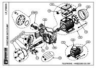
O<br />
CUBE MC SPARE PARTS<br />
O1<br />
CUBE MC EXPLODED VIEW<br />
48
E<br />
O2<br />
LIST OF CUBE MC COMPONENTS<br />
Position<br />
1<br />
2<br />
3<br />
4<br />
5<br />
6<br />
7<br />
8<br />
9<br />
10<br />
11<br />
12<br />
13<br />
14<br />
15<br />
16<br />
17<br />
18<br />
19<br />
20<br />
21<br />
22<br />
Description<br />
BOARD PANEL ASSEMBLY KIT<br />
CUBE MC SUN GUARD KIT<br />
HOSE SUPPORT KIT<br />
EQUALISER OPERATION KIT<br />
CUBE MC HINGE KIT<br />
PUMP FASTENING KIT<br />
CUBE MC OPERATING KIT<br />
PANTHER 72 UNIT - 230V/50HZ<br />
CUBE 70/33 MANIFOLD KIT<br />
KIT K600/3 + CABLE 0.5 M<br />
CUBE MC DELIVERY KIT<br />
PUMP CABLE/MC BOX FOR CUBE MC KIT<br />
FOOT VALVE KIT<br />
CUBE MC ROOF KIT<br />
CUBE MC CABLE RETAINER KIT<br />
CUBE MC BASE KIT<br />
CUBE MC STRUCTURE REINFORCEMENT KIT<br />
CUBE MC FRONT DOOR KIT<br />
NOZZLE SEAT CUBE 50<br />
AUTOMATIC NOZZLE 60 1in F BLACK<br />
KEYBOARD + SENSOR KIT<br />
FUSE KIT<br />
Quantity<br />
1<br />
1<br />
1<br />
1<br />
1<br />
1<br />
1<br />
1<br />
1<br />
1<br />
1<br />
1<br />
1<br />
1<br />
1<br />
1<br />
1<br />
1<br />
1<br />
1<br />
1<br />
1<br />
49
E<br />
P<br />
MANUFACTURER'S DETAILS AND AFTER-SALES SERVICE<br />
MANUFACTURER: PIUSI S.p.A.<br />
DOCUMENT TYPE: General description and instructions<br />
for its installation, activation,<br />
use and maintenance<br />
EDITION: Bullettin M<strong>0104</strong> <strong>Rev</strong>. 4<br />
PRODUCT: Diesel fuel dispenser for private use with meter<br />
MODEL: All the models of the CUBE MC range,<br />
with single-phase/three-phase<br />
mechanical/electronic meter,<br />
with various voltages/frequencies<br />
CONFORMITY: CE MARK<br />
(see Declaration of conformity, page 28)<br />
TECHNICAL SUPPORT: Provided by the Service Departments<br />
of our Authorized Resellers<br />
The information contained in this manual is provided by the Manufacturer, who reserves the<br />
right to make changes without prior notice.<br />
50
NOTE<br />
51
52<br />
NOTE
NOTE<br />
53
54<br />
NOTE
Impaginazione e grafica: NEGRINI&VARETTO, Modena<br />
www.negrinievaretto.com<br />
Traduzioni: FERRARI STUDIO, Suzzara (Mn)<br />
www.ferraristudio.it<br />
Stampa: LA CITTADINA, Gianico (Bs)<br />
www.lacittadina.it<br />
55
Authorized reseller's stamp<br />
Timbre du revendeur autorisé<br />
Stempel des autorisierten Vertragshändlers<br />
Timbro del rivenditore autorizzato<br />
M <strong>0104</strong> IT<strong>UK</strong> <strong>Rev</strong>. 4