AVENTOS
AVENTOS - Blum
AVENTOS - Blum
- No tags were found...

Create successful ePaper yourself
Turn your PDF publications into a flip-book with our unique Google optimized e-Paper software.
BLUMOTION<br />
inside<br />
<strong>AVENTOS</strong><br />
Various applications for lift systems<br />
connect.blum.com
<strong>AVENTOS</strong> – Moving solutions for every lift system<br />
2
Use <strong>AVENTOS</strong> to address<br />
individual customer requests<br />
<strong>AVENTOS</strong> is the lift system programme that provides<br />
perfect motion in the wall cabinet area: Even wide lift<br />
systems will open easily and close silently and effortlessly<br />
thanks to BLUMOTION. The variable stop ensures<br />
that <strong>AVENTOS</strong> lift systems always remain in the desired<br />
position. Your customers will be amazed at how easy it is<br />
to use.<br />
These excellent solutions for Bi-Fold, up & over,<br />
lift up & stay lift applications can accommodate many new<br />
design options. We have further enhanced this range with<br />
a new product specifically for small stay-lifts. With these<br />
products you can fulfil all your customers‘ desires by offering<br />
the correct solution for any wall cabinet.<br />
Contents<br />
4 - 7 The lift system programme<br />
18 - 29 <strong>AVENTOS</strong> HF<br />
8 - 10 Inspirational action<br />
30 - 37 <strong>AVENTOS</strong> HS<br />
10 - 11 Inspiring quality<br />
38 - 45 <strong>AVENTOS</strong> HL<br />
12 - 13 Easy assembly and adjustment<br />
46 - 53 <strong>AVENTOS</strong> HK<br />
14 - 15 Programme with many options<br />
54 - 63 TIP-ON for <strong>AVENTOS</strong> HK<br />
16 - 17 Harmonious design<br />
64 - 71 <strong>AVENTOS</strong> HK-S<br />
3
The lift system programme<br />
<strong>AVENTOS</strong> HF<br />
for bi-fold lift systems<br />
■■Ideal for higher wall cabinets because<br />
the handle remains easy to reach in<br />
any position.<br />
■■Due to the two-part front, the space<br />
requirement at the top is low for very<br />
high cabinet heights.<br />
■■<strong>AVENTOS</strong> HF can also be used with<br />
fronts of different heights.<br />
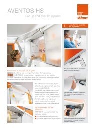
<strong>AVENTOS</strong> HS<br />
for up & over lift systems<br />
■■Ideal for large-area, single fronts.<br />
■<br />
■ Space requirement above the cabinet<br />
is minimised due to highly engineered<br />
movement.<br />
■■You can also use cornice or crown<br />
moulding with <strong>AVENTOS</strong> HS.<br />
<strong>AVENTOS</strong> HL<br />
for lift ups<br />
■■Ideal for applications in high or wall<br />
cabinets with fronts above as well as<br />
recessed cabinets.<br />
■■Well-suited for small-area,<br />
single fronts.<br />
■■<strong>AVENTOS</strong> HL can be used in isolation<br />
with low wall cabinets.<br />
4
Versatile application<br />
There are many good reasons why <strong>AVENTOS</strong> lift systems are a good choice<br />
for the wall cabinet.<br />
Because lift systems open upwards, they provide an excellent view into the cabinet<br />
interior. This enables comfortable and ergonomic access to the items stored.<br />
The furniture user retains freedom of motion, unhindered by the lift mechanism.<br />
Additionally, lift systems can offer a huge variety of design options for wide fronts.<br />
The visual effect achieved on the base units can often be replicated on the wall<br />
cabinets.<br />
<strong>AVENTOS</strong> HK<br />
for stay lifts<br />
■■Ideal solution for low cabinet heights<br />
in the wall cabinet.<br />
■■<strong>AVENTOS</strong> HK requires only a small<br />
amount of space at the top due to the<br />
pivot action.<br />
■■No hinges are required.<br />
TIP-ON for <strong>AVENTOS</strong> HK<br />
for small stay lifts<br />
■■Easy to open with just a light touch<br />
■<br />
■■Excellent durability.<br />
■<br />
■ Mechanical opening support system<br />
■ Ideal solution for handle-less cabinets<br />
<strong>AVENTOS</strong> HK-S<br />
for small stay lifts<br />
■■Ideal solution for small cabinets,<br />
e.g. over the larder unit or refrigerator,<br />
can use as a dishrack cabinet<br />
■■<strong>AVENTOS</strong> HK-S requires only a small<br />
amount of space at the top due to the<br />
pivot action.<br />
■■No hinges are required.<br />
5
The lift system programme<br />
Choosing the right<br />
lift system<br />
The following graphic shows where the six <strong>AVENTOS</strong> programme types can be used in a common<br />
kitchen system.<br />
<strong>AVENTOS</strong> HK-S<br />
<strong>AVENTOS</strong> HL<br />
<strong>AVENTOS</strong> HL <strong>AVENTOS</strong> HF <strong>AVENTOS</strong> HS <strong>AVENTOS</strong> HS <strong>AVENTOS</strong> HF <strong>AVENTOS</strong> HS<br />
<strong>AVENTOS</strong> HL<br />
<strong>AVENTOS</strong> HK<br />
TIP-ON for<br />
<strong>AVENTOS</strong> HK<br />
<strong>AVENTOS</strong> HS<br />
<strong>AVENTOS</strong> HL<br />
<strong>AVENTOS</strong> HK/<br />
TIP-ON for<br />
<strong>AVENTOS</strong> HK<br />
<strong>AVENTOS</strong> HK/<br />
TIP-ON for<br />
<strong>AVENTOS</strong> HK<br />
<strong>AVENTOS</strong><br />
HK-S<br />
17 R<br />
16 R<br />
15 R<br />
14 R<br />
13 R<br />
12 R<br />
11 R<br />
10 R<br />
9 R<br />
8 R<br />
7 R<br />
6 R<br />
5 R<br />
4 R<br />
3 R<br />
2 R<br />
1 R<br />
High cabinet<br />
Wall cabinet<br />
Recess<br />
R<br />
System*<br />
* <strong>AVENTOS</strong> can also be used in common 4 systems in the wall cabinet area.<br />
6
<strong>AVENTOS</strong><br />
at a glance<br />
Area of application<br />
Higher wall cabinets<br />
Medium wall cabinets<br />
Low wall cabinets<br />
High cabinets<br />
Room planning<br />
Min. top space requirement<br />
Design<br />
Single front<br />
Two-part front<br />
Can be combined with cornice or<br />
crown moulding<br />
Cabinet height dimensions in mm<br />
HF<br />
X<br />
X<br />
X<br />
X<br />
HS<br />
X<br />
X<br />
X<br />
HL<br />
X<br />
X<br />
X<br />
480–1.040 350–800 300–580<br />
HK/TIP-ON for<br />
<strong>AVENTOS</strong> HK<br />
X<br />
X<br />
X<br />
up to 600*<br />
HK-S<br />
X<br />
X<br />
X X X X<br />
X X X X<br />
X<br />
X<br />
max. 400<br />
Cabinet width dimensions in mm<br />
Ergonomics<br />
Handles within easy reach<br />
Good access to cabinet interior<br />
up to<br />
1.800<br />
X<br />
X<br />
up to<br />
1.800<br />
up to<br />
1.800<br />
up to<br />
1.800<br />
**<br />
X X X X<br />
X X X X<br />
* For ergonomic reasons, we recommend a maximum cabinet height of 600 mm. However, higher lift systems can also be used<br />
subject to the power factor limits (see page 48).<br />
** Depending on the power factor<br />
DYNAMIC SPACE is a marketing tool from Blum that helps to make good arguments for adding high-quality equipment to a<br />
kitchen: Better ergonomics, more comfort and more fun in the kitchen.<br />
www.dynamicspace.com<br />
7
Motion that inspires<br />
BLUMOTION<br />
inside<br />
8
Four ways of experiencing<br />
Perfect Motion<br />
Surprise and fascinate your<br />
customers:<br />
Frontals open effortlessly with all<br />
<strong>AVENTOS</strong> options. Even heavy fronts<br />
only require light operating forces. The<br />
variable stop means that fronts always<br />
remain in the desired position. This<br />
ensures that the handle is always within<br />
easy reach.<br />
<strong>AVENTOS</strong> also offers a high degree<br />
of elegance and comfort when closing.<br />
The intelligent technology of the<br />
BLUMOTION adaptive system ensures<br />
that fronts always close silently and<br />
effortlessly – regardless of the size,<br />
weight and closing speed.<br />
9
Quality<br />
<strong>AVENTOS</strong> HF<br />
Fine adjustment screw<br />
BLUMOTION – Open<br />
Spring package<br />
BLUMOTION – Close<br />
Drop curve<br />
<strong>AVENTOS</strong> HS<br />
Fine adjustment screw<br />
BLUMOTION – Open<br />
Spring package<br />
Drop curve<br />
BLUMOTION – Close<br />
<strong>AVENTOS</strong> HL<br />
Fine adjustment screw<br />
BLUMOTION – Open<br />
Spring package<br />
BLUMOTION – Close<br />
Drop curve<br />
10
Quality –<br />
for the lifetime of the furniture<br />
<strong>AVENTOS</strong> lift systems will bring your customers years of happiness.<br />
The core of these fitting solutions is the lift mechanism with BLUMOTION and<br />
a robust spring package. This ensures high durability and ease of use when opening<br />
and closing.<br />
<strong>AVENTOS</strong> HK<br />
Lever<br />
Fine adjustment<br />
screw<br />
Spring<br />
package<br />
BLUMOTION – Close<br />
<strong>AVENTOS</strong> HK-S<br />
BLUMOTION – Close<br />
Lever<br />
Spring<br />
Fine adjustment screw<br />
11
Assembly<br />
12
Perfect assembly and accurate<br />
adjustment made easy<br />
Assembly and adjustment need to be<br />
precise if you are to guarantee that your<br />
customers receive the full “<strong>AVENTOS</strong><br />
experience”.<br />
The lift force can be adjusted (according<br />
to the frontal weight) using a power screw<br />
driver (Pozidriv ® , size 2, length 39 mm).<br />
To make adjustment easier all <strong>AVENTOS</strong><br />
mechanisms include a calibrated scale.<br />
<strong>AVENTOS</strong> components are light,<br />
regardless of the frontal size, and can<br />
be assembled quickly and easily.<br />
Thanks to proven CLIP technology,<br />
assembly is almost entirely tool-free.<br />
Fronts can be adjusted in 3 dimensions<br />
to ensure the correct gap alignment.<br />
13
Programme<br />
14
Every conceivable application<br />
within a concise programme<br />
The <strong>AVENTOS</strong> programme comprises of<br />
a minumum number of symmetrical parts<br />
that can be used in multiple applications.<br />
With a straightforward programme of<br />
lift mechanisms and lever arms, practically<br />
all front sizes and door weights are<br />
covered. The programme encompasses<br />
cabinet widths up to 1800 mm as well as<br />
every conceivable cabinet height.<br />
<strong>AVENTOS</strong> opens up numerous design<br />
options:<br />
All programmes can be combined with<br />
composite frontals (wood, MFC, MDF,<br />
etc) as well as narrow and wide aluminium<br />
frames.<br />
15
Design<br />
16
Harmonious design and<br />
high functionality<br />
Technology that inspires.<br />
Along with high functionality,<br />
the <strong>AVENTOS</strong> programme also inspires<br />
through its simple yet elegant design.<br />
This was also the opinion of the expert<br />
jury at the 2007 Interzum Awards.<br />
As winner of the "best of the best"<br />
category. This award was won by<br />
<strong>AVENTOS</strong> on the combined strengths of;<br />
unsurpassed function and sleek design.<br />
The lift system won the "red dot award<br />
for product design" in 2008 and was<br />
nominated for the "Design Prize from the<br />
Federal Republic of Germany" in 2009.<br />
17
<strong>AVENTOS</strong> HF<br />
The bi-fold lift system can be used in<br />
the kitchen and living area.<br />
Whether wooden fronts, narrow or wide<br />
alu frames or a combination of different<br />
materials: <strong>AVENTOS</strong> HF creates numerous<br />
design options. It can also be used<br />
with fronts of different heights.<br />
18
Other persuasive advantages<br />
22 mm<br />
480 – 1.040 mm<br />
Handle position<br />
22 mm<br />
up to 1.800 mm<br />
Small programme –<br />
wide range of solutions<br />
<strong>AVENTOS</strong> HF completely covers all<br />
common lift system widths and heights<br />
with just one small programme. The<br />
product line comprises 3 lift mechanisms<br />
and 4 telescopic arms. What‘s more; all<br />
main components are symmetrical.<br />
The narrow programme range<br />
simplifies ordering, commissioning<br />
and warehousing.<br />
<strong>AVENTOS</strong> HF is suitable for cabinet<br />
widths up to 1.800 mm and for cabinet<br />
heights from 480 to 1.040 mm.<br />
Free positioning of handles<br />
Every type of handle can be used alongside<br />
<strong>AVENTOS</strong> HF. Ideally the handle<br />
should be located near the bottom edge<br />
of the lower frontal to ensure that it is<br />
always within easy reach. <strong>AVENTOS</strong> HF<br />
can also be used with handle-less<br />
frontals (where the lower frontal slightly<br />
overhangs the underside of the cabinet).<br />
Similar shelves possible<br />
Optimal use of storage space: Lift<br />
mechanisms are attached so that<br />
depending on the height of the cabinet<br />
up to two identical shelves can be used<br />
(with a space allowance/cut back of only<br />
22 mm).<br />
Includes a finger safety feature<br />
The CLIP top centre hinge is characterized<br />
by an innovative “release” feature<br />
that ensures finger safety.<br />
No protruding parts<br />
As the telescopic arm can be removed,<br />
there are no protruding parts to obstruct<br />
internal transport during furniture<br />
manufacturing. This is also an advantage<br />
during kitchen assembly.<br />
19
<strong>AVENTOS</strong> HF<br />
Assembly in<br />
just a few steps<br />
Nearly all steps are tool-free thanks to CLIP assembly. We recommend removing the front for safe<br />
and easy cabinet assembly onsite. This is also made very easy with CLIP technology.<br />
1. The telescopic arms are attached<br />
to the lift mechanism using CLIP<br />
technology.<br />
2.<br />
The upper front is placed on the<br />
telescopic arm and CLIP top hinges<br />
are attached.<br />
3.<br />
CLIP top centre hinges are used to<br />
connect both fronts.<br />
Warning<br />
There is a danger of injury if the telescopic<br />
arm springs upward. Remove the<br />
telescopic arm rather than pushing it<br />
down.<br />
Special warning and safety information<br />
must be sent out when used in North<br />
America.<br />
4.<br />
The telescopic arm and lower front<br />
are connected to each other via the<br />
CLIP mechanism.<br />
20
Quick adjustment,<br />
precise adjustment<br />
Both bi-fold lift system fronts can be adjusted in all 3 dimensions for a precise gap design.<br />
The fine adjustment for the opening and closing forces for <strong>AVENTOS</strong> HF is carried out using a<br />
power screwdriver. The force can be adjusted precisely to the corresponding door weight. It’s child’s<br />
play thanks to the integrated callibrated scale.<br />
Perfect motion requires precise adjustment:<br />
1.<br />
Simple and infinitely variable: A power<br />
screwdriver is used to properly set<br />
the lift mechanism (Pozidriv ® , size 2,<br />
length 39 mm).<br />
If the front falls when let go, it must be<br />
turned clockwise.<br />
If the front rises when let go, it must be<br />
turned anti-clockwise.<br />
2. The telescopic arms adjust themselves<br />
by closing the front. They are the fronts using the CLIP top centre<br />
3. You can set the desired gap between<br />
fastened using the centre lever. This hinge.<br />
process also adjusts the tensions in<br />
the front.<br />
21
Order specifications<br />
Wooden fronts and wide alu frames symmetrical/asymmetrical<br />
3 types of lift mechanisms are<br />
enough to cover a wide range<br />
of applications.<br />
Using the power factor, you can<br />
calculate the required lift mecha-<br />
3a<br />
3b<br />
7<br />
5<br />
1 2<br />
8<br />
6<br />
4<br />
nisms. The power factor required<br />
depends on the weight of the lower<br />
and upper front (incl. handle) and<br />
cabinet height.<br />
The power factor and the door<br />
weight can be increased by 50%<br />
when a third lift mechanism is used.<br />
The larger front must be at the top<br />
for asymmetrical fronts.<br />
This is how it’s done: Power factor LF = cabinet height 1) [mm] x door weight including handle [kg]<br />
LF 2.600–5.500<br />
20F2201.05<br />
20F2201.05 20F2501.05<br />
LF 960–2.650<br />
LF 5.350–10.150<br />
LF 9.000–17.250<br />
20F2801.05<br />
20F2801.05<br />
LF 13.500–25.900<br />
Lift mechanism one-sided Lift mechanism two-sided Additional 3rd lift mechanism<br />
A trial application is recommended when you are in a borderline area for the individual lift mechanism.<br />
LF Power factor<br />
1<br />
Lift mechanism set<br />
2<br />
Telescopic arm set<br />
Power factor LF<br />
Nickel plated steel<br />
960–2.650 1 x 20F2201.05<br />
Cabinet height 1) 480-570 mm<br />
20F3201<br />
2.600–5.500<br />
2 x<br />
20F2201.05<br />
Cabinet height 1) 560-710 mm<br />
20F3501<br />
5.350–10.150<br />
2 x<br />
20F2501.05<br />
Cabinet height 1) 700-900 mm<br />
20F3801<br />
9.000–17.250<br />
2 x<br />
20F2801.05<br />
Cabinet height 1) 760-1,040 mm<br />
20F3901<br />
13.500–25.900<br />
3 x<br />
20F2801.05<br />
Composed of:<br />
Composed of:<br />
2 x symmetrical telescopic arms<br />
2 x symmetrical lift mechanisms<br />
1)<br />
"Theoretical cabinet height" for asymmetrical fronts = upper front height (FHO) x 2 (including gaps)<br />
22
3<br />
Cover cap set<br />
7<br />
CLIP top 120° hinge<br />
light grey, silk white, nickel plated<br />
Boss:<br />
Steel boss<br />
Screws 2)<br />
unsprung<br />
70T5550.TL<br />
Composed of:<br />
3a<br />
2 x cover plates left/right<br />
20F8001<br />
3b<br />
2 x round cover caps<br />
20F9001.BL<br />
8<br />
CLIP top centre hinge<br />
4<br />
Mounting plate for telescopic arm<br />
All horizontal mounting plates with 0 mm distance<br />
Boss:<br />
Zinc boss<br />
Screws 2)<br />
unsprung<br />
78Z5500T<br />
Recommendation<br />
Screws 2)<br />
Spacing 0 mm<br />
175H5400<br />
Optional:<br />
Opening angle stop<br />
5<br />
Mounting plate for CLIP top 120° hinge<br />
83°<br />
20F7011<br />
Standard mounting plates, spacing depends on the top gap<br />
104°<br />
20F7051<br />
Recommendation<br />
Bit PZ cross slot<br />
Screws 2)<br />
Spacing 0 mm<br />
175H5400<br />
Size 2, length 39 mm<br />
BIT-PZ KS2<br />
6<br />
Mounting plate for CLIP top centre hinge<br />
Standard mounting plates with 0 mm distance<br />
Recommendation<br />
Screws 2)<br />
Spacing 0 mm<br />
Only use a cruciform mounting plate for wide alu frames<br />
under a 55 mm frame width<br />
175H5400<br />
2)<br />
Use chipboard screws (609.1x00) for wooden fronts. Use self tapping screw, countersunk head (608.085) for wide alu frames.<br />
23
Planning Information<br />
Wooden fronts and wide alu frames symmetrical<br />
Peg positions for lift mechanism<br />
Fixing positions for lift mechanism<br />
Space requirement<br />
13.5<br />
24<br />
21<br />
<br />
<br />
<br />
<br />
<br />
266<br />
229<br />
52<br />
37<br />
* Drilling depth 5 mm<br />
Cabinet height KH<br />
H<br />
480–549 mm KH x 0.3 - 28 mm<br />
4 x Ø 4 x 35 mm<br />
KH<br />
Cabinet height<br />
550–1.040 mm KH x 0.3 - 57 mm<br />
Front assembly<br />
CLIP top 120° hinge unsprung<br />
CLIP top centre hinge<br />
SFA Side front overlay<br />
Cabinet height KH<br />
<br />
<br />
3 hinges starting at cabinet width 1200 mm<br />
and/or 12 kg door weight<br />
4 hinges starting at cabinet width 1800 mm<br />
and/or 20 kg door weight<br />
X<br />
Screw-on/<br />
EXPANDO<br />
X<br />
Knock-in<br />
480–549 mm 68 mm 70 mm<br />
550–1.040 mm 45 mm 47 mm<br />
F Gap<br />
Drilling distance TB<br />
Front overlay FA<br />
5 6 7 8 9 10 11 12 13 14 15 16 17<br />
0<br />
3 4 5 6<br />
3<br />
3 4 5 6<br />
6<br />
3 4 5 6<br />
9 3 4 5 6<br />
Mounting plate<br />
Min. gap F = 1.5 mm<br />
Drilling distance TB<br />
Centre gap F<br />
0<br />
3<br />
6<br />
9<br />
Mounting plate<br />
<br />
* 37 mm for cruciform mounting plates (37/32)<br />
<br />
<br />
3 4 5 6<br />
6<br />
5 4 3<br />
Screw-on<br />
INSERTA/knock-in/EXPANDO assembly<br />
Space requirement<br />
OEB =<br />
Opening angle stop<br />
Without OEB<br />
OEB 104°<br />
OEB 83°<br />
Y = FH x 0.44 + 38<br />
Y = FH x 0.24 + 34<br />
Y = 0<br />
24
Wooden fronts and wide alu frames asymmetrical<br />
Peg positions for lift mechanism<br />
Fixing positions for lift mechanism<br />
Space requirement<br />
13.5 24<br />
21<br />
266<br />
229<br />
52<br />
37<br />
* Drilling depth 5 mm<br />
TKH<br />
H<br />
480–549 mm TKH x 0.3 - 28 mm<br />
550–1.040 mm TKH x 0.3 - 57 mm<br />
4 x Ø 4 x 35 mm<br />
TKH Theoretical cabinet height<br />
FHo Upper front height<br />
FHu Lower front height<br />
TKH = FHo mm x 2 (including gaps)<br />
Front assembly<br />
CLIP top 120° hinge unsprung<br />
CLIP top centre hinge<br />
<br />
<br />
* 37 mm for cruciform<br />
mounting plates<br />
(37/32)<br />
F<br />
Gap<br />
<br />
Min. gap F = 1.5 mm<br />
FHo Upper front height<br />
Drilling distance TB<br />
Drilling distance TB<br />
TKH Theoretical cabinet height<br />
SFA Side front overlay<br />
FAu Lower front overlay<br />
TKH<br />
X<br />
Screw-on/<br />
EXPANDO<br />
X<br />
Knock-in<br />
0<br />
3<br />
6<br />
Front overlay FA<br />
5 6 7 8 9 10 11 12 13 14 15 16 17<br />
3 4 5 6<br />
3 4 5 6<br />
3 4 5 6<br />
0<br />
3<br />
6<br />
Centre gap F<br />
<br />
<br />
3 4 5 6<br />
6 5 4 3<br />
480–549 mm FHo/2 + 68 mm<br />
FHo/2 + 70 mm<br />
9<br />
3<br />
4<br />
5 6<br />
9<br />
550–1.040 mm FHo/2 + 45 mm<br />
FHo/2 + 47 mm<br />
Mounting plate<br />
Mounting plate<br />
Min. lower front height Number of Hinges Space requirement<br />
X + 19 + FAu<br />
3 hinges starting at cabinet width 1200 mm<br />
and/or 12 kg door weight<br />
4 hinges starting at cabinet width 1800 mm<br />
and/or 20 kg door weight<br />
<br />
<br />
FAu Lower front overlay<br />
Screw-on<br />
INSERTA/knock-in/EXPANDO assembly<br />
OEB = Opening angle stop<br />
Without OEB<br />
OEB 104°<br />
OEB 83°<br />
Y = FH x 0.44 + 38<br />
Y = FH x 0.24 + 34<br />
Y = 0<br />
25
Order specifications<br />
Narrow alu frames symmetrical/asymmetrical<br />
3 types of lift mechanisms are<br />
enough to cover a wide range<br />
of applications.<br />
Using the power factor, you can calculate<br />
the required lift mechanisms.<br />
The power factor required depends<br />
on the weight of the lower and upper<br />
3a<br />
3b<br />
7<br />
5<br />
8<br />
6<br />
front and the cabinet height.<br />
The larger front must be at the top<br />
for asymmetrical fronts.<br />
1 2 4<br />
This is how it’s done: Power factor LF = cabinet height 1) [mm] x door weight including handle [kg]<br />
LF 2.600–5.500<br />
20F2201.05<br />
20F2201.05 20F2501.05<br />
LF 960–2.650<br />
LF 5.350–10.150<br />
LF 9.000–17.250<br />
20F2801.05<br />
Lift mechanism one-sided<br />
Lift mechanism two-sided<br />
A trial application is recommended when you are in a borderline area for the individual lift mechanism.<br />
LF Power factor<br />
1<br />
Lift mechanism set<br />
2<br />
Telescopic arm set<br />
Power factor LF<br />
Nickel plated steel<br />
2.600–5.500<br />
20F2201.05<br />
Cabinet height 1) 480-570 mm<br />
20F3201<br />
5.350–10.150<br />
20F2501.05<br />
Cabinet height 1) 560-710 mm<br />
20F3501<br />
9.000–17.250<br />
20F2801.05<br />
Cabinet height 1) 700-900 mm<br />
20F3801<br />
Composed of:<br />
Cabinet height 1) 760-1,040 mm<br />
20F3901<br />
2 x symmetrical lift mechanisms<br />
Composed of:<br />
2 x symmetrical telescopic arms<br />
1)<br />
"Theoretical cabinet height" for asymmetrical fronts = upper front height (FHO) x 2 (including gaps)<br />
26
3<br />
Cover cap set<br />
7<br />
CLIP top 120° alu frame hinge<br />
light grey, silk white, nickel plated<br />
Boss:<br />
Steel boss<br />
Screw-on<br />
unsprung<br />
72T550A.TL<br />
Composed of:<br />
3a<br />
2 x cover plates left/right<br />
20F8001<br />
3b<br />
2 x round cover caps<br />
20F9001<br />
8<br />
CLIP top alu frame centre hinge<br />
4<br />
CLIP adapter plate for telescopic arms<br />
Boss:<br />
Zinc boss<br />
Screw-on<br />
unsprung<br />
78Z550AT<br />
Distance 0 mm left/right<br />
175H5B00<br />
Optional:<br />
Opening angle stop<br />
5<br />
Mounting plate for CLIP top 120° hinge<br />
83°<br />
20F7011<br />
Standard mounting plates, spacing depends on the top gap<br />
104°<br />
20F7051<br />
Recommendation<br />
Bit PZ cross slot<br />
Screw-on<br />
Spacing 0 mm<br />
175H5400<br />
Size 2, length 39 mm<br />
BIT-PZ KS2<br />
6<br />
CLIP adapter plate for centre hinges<br />
Symmetrical<br />
175H5A00<br />
27
Planning Information<br />
Narrow alu frames symmetrical<br />
Peg positions for lift mechanism<br />
Fixing positions for lift mechanism<br />
Space requirement<br />
13.5 24<br />
21<br />
<br />
<br />
<br />
<br />
<br />
266<br />
229<br />
52<br />
37<br />
* Drilling depth 5 mm<br />
Cabinet height KH<br />
H<br />
4 x Ø 4 x 35 mm<br />
KH<br />
Cabinet height<br />
480–549 mm KH x 0.3 - 28 mm<br />
550–1.040 mm KH x 0.3 - 57 mm<br />
Front assembly<br />
CLIP top 120°<br />
alu frame hinge unsprung<br />
CLIP top alu frame centre hinge<br />
3 hinges starting at cabinet width 1200 mm<br />
and/or 12 kg door weight<br />
4 hinges starting at cabinet width 1800 mm<br />
and/or 20 kg door weight<br />
Cabinet height KH<br />
X<br />
Min. gap F = 1.5 mm<br />
480–549 mm<br />
54 mm<br />
550–1.040 mm 31 mm<br />
An adjustment has to be made for frame<br />
thicknesses over 20.5 mm<br />
Front assembly<br />
Space requirement<br />
* When changing material thickness, adjust<br />
the assembly dimensions accordingly<br />
<br />
<br />
OEB =<br />
Opening angle stop<br />
<br />
<br />
<br />
Without OEB<br />
OEB 104°<br />
OEB 83°<br />
Y = FH x 0.44 + 38<br />
Y = FH x 0.24 + 34<br />
Y = 0<br />
28
Narrow alu frames asymmetrical<br />
Peg positions for lift mechanism<br />
Fixing positions for lift mechanism<br />
Space requirement<br />
13.5 24<br />
21<br />
266<br />
229<br />
52<br />
37<br />
* Drilling depth 5 mm<br />
TKH Theoretical cabinet height<br />
TKH<br />
H<br />
FHo Upper front height<br />
480–549 mm<br />
TKH x 0.3 - 28 mm<br />
4 x Ø 4 x 35 mm<br />
FHu Lower front height<br />
550–1.040 mm<br />
TKH x 0.3 - 57 mm<br />
TKH = FHo mm x 2 (including gaps)<br />
Front assembly<br />
CLIP top 120°<br />
alu frame hinge unsprung<br />
CLIP top alu frame centre hinge<br />
FHo Upper front height<br />
TKH Theoretical cabinet height<br />
FAu Lower front overlay<br />
TKH<br />
X<br />
480–549 mm FHo/2 + 54 mm<br />
550–1.040 mm FHo/2 + 31 mm<br />
Min. gap F = 1.5 mm<br />
An adjustment has to be made for frame<br />
thicknesses over 20.5 mm<br />
Min. lower front height<br />
Number of Hinges<br />
Space requirement<br />
X + 33 + FAu<br />
3 hinges starting at cabinet width 1200 mm<br />
and/or 12 kg door weight<br />
4 hinges starting at cabinet width 1800 mm<br />
and/or 20 kg door weight<br />
<br />
<br />
FAu Lower front overlay<br />
Screw-on<br />
* When changing material thickness, adjust<br />
the assembly dimensions accordingly<br />
OEB = Opening angle stop<br />
Without OEB<br />
Y = FH x 0.44 + 38<br />
<br />
<br />
<br />
<br />
OEB 104°<br />
OEB 83°<br />
Y = FH x 0.24 + 34<br />
Y = 0<br />
29
<strong>AVENTOS</strong> HS<br />
Design freedom for cornice<br />
or crown mouldings.<br />
The <strong>AVENTOS</strong> HS up & over lift system<br />
can easily be combined with cabinets<br />
fitted with cornice or crown mouldings<br />
because the frontal swings up over the<br />
cabinet with enough space.<br />
<strong>AVENTOS</strong> HS opens up a variety of<br />
design options.<br />
30
Other persuasive advantages<br />
350-800 mm<br />
22 mm<br />
up to 1,800 mm<br />
Small programme,<br />
huge application variety<br />
<strong>AVENTOS</strong> HS completely covers all<br />
common frontal widths and heights with<br />
one simple programme: 9 different lift<br />
mechanisms and only 1 lever arm cover<br />
every size and front weight.<br />
<strong>AVENTOS</strong> HS is suitable for cabinet<br />
widths up to 1800 mm and for cabinet<br />
heights from 350 to 800 mm. The narrow<br />
programme range simplifies ordering,<br />
commissioning and warehousing.<br />
Because of its symmetrical design, the<br />
lift mechanism can be used on both the<br />
right and left.<br />
Option of shelves<br />
With <strong>AVENTOS</strong> HS, storage space is<br />
optimised in wall cabinets. Even smaller<br />
wall cabinets can be easily fitted with a<br />
shelf. A shelf with a recess of only<br />
22 mm from the front can be used starting<br />
at a cabinet height of 500 mm. Starting<br />
with a cabinet height of 740 mm, two<br />
shelves are possible.<br />
No protruding parts<br />
There are no protruding parts thanks<br />
to the removable lever arm. This guarantees<br />
a high degree of safety during<br />
internal transport, furniture manufacturing<br />
and delivery to the customer.<br />
31
<strong>AVENTOS</strong> HS<br />
Assembly in<br />
just a few steps<br />
<strong>AVENTOS</strong> HS assembly is almost entirely tool-free. For final assembly onsite, the wall cabinet front<br />
can be removed and then later reattached without the use of tools thanks to proven CLIP technology.<br />
This makes cabinet assembly easier, faster and safer.<br />
1. The lift mechanism is attached. 2. The cross stabiliser is attached to 3.<br />
Installing the lever arm requires no the lift mechanism for optimal side<br />
tools.<br />
stability.<br />
The symmetrical front fixing bracket is<br />
attached to the front.<br />
Warning<br />
There is a danger of injury if the lever arm<br />
HL springs upward. Remove the lever<br />
arm HL rather than pushing it down.<br />
Special warning and safety information<br />
must be added for use in North America.<br />
4.<br />
The lever arm and the front are connected<br />
via the CLIP mechanism.<br />
32
Quick adjustment,<br />
precise adjustment<br />
The front can be adjusted quickly in all 3 dimensions. Width, depth and height adjustment can be<br />
carried out onsite for perfect gap alignment.<br />
Perfect motion requires a precise setting:<br />
1.<br />
Lift mechanisms are set to the respective<br />
door weight using a power<br />
screwdriver (Pozidriv © , size 2,<br />
length 39 mm).<br />
If the lift system falls when let go,<br />
it must be turned to the right.<br />
If the lift system rises when let go,<br />
it must be turned to the left.<br />
2.<br />
The front can be manually adjusted<br />
in all 3 dimensions.<br />
33
Order specifications<br />
3b<br />
3a 5<br />
4<br />
2<br />
2<br />
2<br />
1<br />
Lift mechanism set<br />
Cabinet height 350-525<br />
20S2A01.05<br />
20S2B01.05<br />
20S2C01.05<br />
Cabinet height 526-675<br />
20S2D01.05<br />
20S2E01.05<br />
20S2F01.05<br />
Cabinet height 676-800<br />
20S2G01.05<br />
20S2H01.05<br />
20S2I01.05<br />
Composed of:<br />
2 x symmetrical lift mechanisms<br />
2<br />
Lever arm set<br />
5<br />
Cross stabiliser rod round<br />
Nickel plated steel<br />
20S3501.05<br />
Alu, Ø 16 mm<br />
Composed of:<br />
For cutting to size, 1061 mm<br />
20Q1061U<br />
2 x level arm left/right<br />
Stabiliser adapters and cover caps<br />
3<br />
Cover cap set<br />
2 x stabiliser adapters<br />
20Q0002<br />
light grey, silk white, nickel plated<br />
2 x cross stabiliser cover caps<br />
20Q0003<br />
3a<br />
3b<br />
Composed of:<br />
2 x cover plates left/right<br />
2 x round cover caps<br />
20S8001<br />
20S9001<br />
Optional:<br />
Bit PZ cross slot<br />
Size 2, length 39 mm<br />
BIT-PZ KS2<br />
4<br />
Front fixing bracket set<br />
Connecting piece for cross stabiliser set<br />
Nickel plated<br />
Alu, Ø 16 mm, KB 1219 mm and higher<br />
20Q091Z<br />
Wooden fronts and wide alu frames 1)<br />
20S4201<br />
Composed of:<br />
Narrow alu frames<br />
Composed of:<br />
20S4201A<br />
1 x connecting piece, 1 x fixing, 2 x connectors, 2 x cover<br />
caps<br />
2 x symmetrical front fixing brackets<br />
1)<br />
Use 4 chipboard screws (609.1x00) for wooden fronts. Use 4 self tapping screw, countersunk head (608.085) for wide alu frames.<br />
34
The cabinet front and door weight is required in order to select<br />
the correct lift mechanism.<br />
Example:<br />
KH (mm)<br />
20S2E01.05<br />
20S2G01.05 20S2H01.05 20S2I01.05<br />
800 4.00–7.00 6.00–12.25 10.50–20.00<br />
795 4.00–7.00 6.00–12.25 10.50–20.00<br />
790 4.00–7.00 6.00–12.25 10.75–20.00<br />
785 4.00–7.00 6.25–12.50 10.75–20.00<br />
780 4.00–7.00 6.25–12.50 10.75–20.25<br />
775 3.75–7.00 6.25–12.50 11.00–20.25<br />
770 3.75–7.00 6.25–12.50 11.00–20.25<br />
765 3.75–7.25 6.50–12.50 11.00–20.25<br />
760 3.75–7.25 6.50–12.75 11.25–20.25<br />
755 3.75–7.25 6.50–12.75 11.25–20.50<br />
750 3.50–7.25 6.50–12.75 11.50–20.50<br />
745 3.50–7.25 6.50–12.75 11.50–20.50<br />
740 3.50–7.25 6.50–12.75 11.75–20.75<br />
735 3.50–7.50 6.50–13.00 11.75–20.75<br />
730 3.50–7.50 6.75–13.00 11.75–21.00<br />
725 3.50–7.50 6.75–13.00 12.00–21.00<br />
720 3.50–7.50 6.75–13.00 12.00–21.25<br />
715 3.50–7.50 6.75–13.00 12.00–21.25<br />
710 3.50–7.75 6.75–13.25 12.25–21.25<br />
705 3.50–7.75 6.75–13.25 12.25–21.50<br />
700 3.50–7.75 6.75–13.25 12.50–21.50<br />
695 3.50–7.75 6.75–13.25 12.50–21.50<br />
690 3.50–7.75 6.75–13.25 12.75–21.50<br />
685 3.50–8.00 7.00–13.25 12.75–21.50<br />
680 3.50–8.00 7.00–13.50 13.00–21.50<br />
676 3.50–8.00 7.00–13.50 13.00–21.50<br />
KH (mm)<br />
Cabinet height KH = 600 mm<br />
Weight of front = 10 kg<br />
Lift mechanism selection =<br />
Cabinet height KH = 602 mm rounded to KH = 600 mm<br />
Cabinet height KH = 603 mm rounded to KH = 605 mm<br />
Door weight (kg)<br />
20S2D01.05 20S2E01.05 20S2F01.05<br />
675 3.00–5.25 5.00–11.00 09.75–19.00<br />
670 3.00–5.25 5.00–11.00 09.75–19.00<br />
665 3.00–5.25 5.00–11.00 09.75–19.00<br />
660 3.00–5.50 5.25–11.25 10.00–19.00<br />
655 3.00–5.50 5.25–11.25 10.00–19.00<br />
650 3.00–5.50 5.25–11.25 10.00–19.00<br />
645 3.00–5.50 5.25–11.25 10.00–18.75<br />
640 3.00–5.50 5.25–11.25 10.00–18.75<br />
635 3.00–5.50 5.25–11.50 10.25–18.75<br />
630 3.00–5.75 5.50–11.50 10.25–18.75<br />
625 3.00–5.75 5.50–11.50 10.25–18.75<br />
620 3.00–5.75 5.50–11.50 10.25–18.75<br />
615 3.00–5.75 5.50–11.50 10.25–18.75<br />
610 3.00–6.00 5.50–11.75 10.50–18.50<br />
605 3.00–6.00 5.50–11.75 10.50–18.50<br />
600 3.00–6.00 5.50–11.75 10.50–18.50<br />
595 3.00–6.00 5.50–11.75 10.50–18.50<br />
590 3.00–6.00 5.50–12.00 10.75–18.25<br />
585 3.00–6.25 5.75–12.00 10.75–18.25<br />
580 3.00–6.25 5.75–12.00 11.00–18.00<br />
575 3.00–6.25 5.75–12.00 11.00–18.00<br />
570 3.00–6.25 5.75-12.25 11.25–17.75<br />
565 3.00–6.25 5.75–12.25 11.25–17.75<br />
560 3.00–6.50 6.00–12.25 11.25–17.50<br />
555 3.00–6.50 6.00–12.50 11.50–17.50<br />
550 3.00–6.50 6.00–12.50 11.50–17.25<br />
545 3.00–6.50 6.00–12.50 11.50–17.25<br />
540 3.00–6.50 6.00–12.75 11.75–17.00<br />
535 3.00–6.75 6.25–12.75 11.75–16.75<br />
530 3.00–6.75 6.25–12.75 11.75–16.75<br />
526 3.00–6.75 6.25–13.00 12.00–16.50<br />
KH (mm)<br />
20S2A01.05 20S2B01.05 20S2C01.05<br />
525 2.50–4.00 3.25–7.50 7.25–15.00<br />
520 2.50–4.00 3.50–7.50 7.25–15.00<br />
515 2.50–4.00 3.50–7.50 7.25–14.75<br />
510 2.50–4.00 3.50–7.75 7.50–14.75<br />
505 2.50–4.00 3.50–7.75 7.50–14.75<br />
500 2.50–4.25 3.50–7.75 7.50–14.75<br />
495 2.50–4.25 3.75–7.75 7.50–14.50<br />
490 2.50–4.25 3.75–8.00 7.75–14.50<br />
485 2.50–4.25 3.75–8.00 7.75–14.25<br />
480 2.50–4.25 3.75–8.00 7.75–14.25<br />
475 2.50–4.25 3.75–8.00 7.75–14.00<br />
470 2.50–4.25 4.00–8.25 8.00–14.00<br />
465 2.25–4.25 4.00–8.25 8.00–13.75<br />
460 2.25–4.25 4.00–8.25 8.00–13.75<br />
455 2.25–4.25 4.00–8.50 8.25–13.50<br />
450 2.25–4.25 4.00–8.50 8.25–13.50<br />
445 2.25–4.50 4.25–8.50 8.25–13.25<br />
440 2.25–4.50 4.25–8.50 8.25–13.00<br />
435 2.25–4.50 4.25–8.75 8.50–13.00<br />
430 2.25–4.50 4.25–8.75 8.50–12.75<br />
425 2.25–4.50 4.25–8.75 8.50–12.75<br />
420 2.25–4.50 4.25–8.75 8.50–12.50<br />
415 2.25–4.50 4.25–8.75 8.50–12.50<br />
410 2.25–4.50 4.25–9.00 8.75–12.25<br />
405 2.25–4.50 4.25–9.00 8.75–12.00<br />
400 2.00–4.75 4.25–9.00 8.75–12.00<br />
395 2.00–4.75 4.50–9.00 8.75–11.75<br />
390 2.00–4.75 4.50–9.00 8.75–11.50<br />
385 2.00–4.75 4.50–9.25 9.00–11.50<br />
380 2.00–4.75 4.50–9.25 9.00–11.25<br />
375 2.00–4.75 4.50–9.25 9.00–11.25<br />
370 2.00–4.75 4.50–9.25 9.00–11.00<br />
365 2.00–4.75 4.50–9.25 9.00–11.00<br />
360 2.00–4.75 4.50–9.50 9.25–10.75<br />
355 2.00–4.75 4.50–9.50 9.25–10.50<br />
350 2.00–5.00 4.50–9.50 9.25–10.50<br />
35
Planning Information<br />
Peg positions for lift mechanism<br />
Fixing positions for lift mechanism<br />
Space requirement<br />
60<br />
42.5<br />
7.5<br />
35<br />
258<br />
230.5<br />
105.5<br />
83*<br />
H<br />
33<br />
35<br />
123<br />
89.5**<br />
5 x Ø 4 x 35 mm<br />
* Drilling depth 5 mm<br />
SOB Top panel thickness<br />
* Left<br />
** Right<br />
Front assembly<br />
Planning narrow alu frames<br />
Narrow alu frames<br />
FAo Upper front overlay<br />
SFA Side front overlay<br />
Wooden fronts<br />
and wide alu<br />
frames 1)<br />
Wall application: Requires 5 mm min. gap<br />
SFA Side front overlay<br />
For frame width 19 mm:<br />
SFA of 11-18 mm possible<br />
* When changing material thickness, adjust the<br />
assembly dimensions accordingly<br />
1)<br />
Use 4 chipboard screws (609.1x00) for wooden fronts. Use 4 self tapping screw, countersunk head (608.085) for wide alu frames.<br />
36
Front setting Cornice and crown moulding clearance Cross stabiliser<br />
[1] KB (KS 16–19mm) - 158 mm<br />
and/or inner width -120 mm<br />
Connecting piece<br />
Gap F<br />
X max<br />
Y max<br />
3 mm<br />
35 mm<br />
101 mm<br />
2 mm<br />
31 mm<br />
101 mm<br />
[2] half KB (KS 16–19mm) -158 mm<br />
Dimensions depend on tilt adjustment<br />
1.5 mm<br />
28 mm<br />
101 mm<br />
KB<br />
Cabinet width<br />
KS<br />
Cabinet thickness<br />
37
<strong>AVENTOS</strong> HL<br />
Full access.<br />
Because the <strong>AVENTOS</strong> HL parallel lift<br />
can be completely raised it provides<br />
excellent access to the cabinet interior.<br />
The different lever arms always ensure<br />
the best access to storage items in the<br />
cabinet interior - even for mid height<br />
cabinets.<br />
38
Other persuasive advantages<br />
300-580 mm<br />
up to 1,800 mm<br />
Small programme – wide range<br />
of solutions<br />
<strong>AVENTOS</strong> HL completely covers all common<br />
lift system widths and heights, and<br />
is also suitable for wide fronts.<br />
<strong>AVENTOS</strong> HL is suitable for cabinet<br />
widths up to 1800 mm and for cabinet<br />
heights from 300 to 580 mm.<br />
Numerous design options<br />
Because the <strong>AVENTOS</strong> HL opens parallel<br />
to the cabinet, it can be used in wall<br />
cabinets or in the upper half of tall units.<br />
At mid-height it can be adapted to conceal<br />
small appliances (i.e. microwaves).<br />
No protruding parts<br />
There are no protruding parts thanks to<br />
the removable lever arm. This makes furniture<br />
manufacturing, transport and final<br />
assembly both easier and safer.<br />
This small programme comprises just<br />
5 different lift mechanisms and 4 lever<br />
arms. This selection enables a variable<br />
stop for every front size and weight.<br />
The straightforward programme range<br />
simplifies ordering, commissioning and<br />
warehousing.<br />
39
<strong>AVENTOS</strong> HL<br />
Assembly in<br />
just a few steps<br />
Nearly all steps for <strong>AVENTOS</strong> HL assembly are tool-free.<br />
We recommend removing and reattaching the fronts later on (again tool-free) for simple,<br />
safe and quick cabinet assembly onsite.<br />
1.<br />
The lever arm is attached to the lift<br />
mechanism without the need for tools.<br />
2. The cross stabiliser is attached to 3.<br />
the lift mechanism for optimal side<br />
stability.<br />
The symmetrical front fixing bracket is<br />
attached to the front.<br />
Warning<br />
There is a danger of injury if the lever arm<br />
HL springs upward. Remove the lever<br />
arm HL rather than pushing it down.<br />
Special warning and safety information<br />
must be added for use in North America.<br />
4.<br />
The lever arm and the front are connected<br />
via the CLIP mechanism.<br />
40
Quick adjustment,<br />
precise adjustment<br />
The front can be adjusted in all 3 dimensions in only a few steps. Therefore the; front height, width<br />
and tilt positions can be precisely set. A calibrated scale is used for the fine adjustment of lift<br />
mechanism opening and closing forces.<br />
Perfect motion requires a precise setting:<br />
1.<br />
Lift mechanisms are set to the respective<br />
door weight using an electric<br />
screwdriver (Pozidriv © , size 2,<br />
length 39 mm).<br />
If the lift system falls when let go, it must<br />
be turned to the right.<br />
If the lift system rises when let go, it must<br />
be turned to the left.<br />
2.<br />
Optimal front adjustment via the 3-dimensional<br />
setting.<br />
41
Order specifications<br />
5 types of lift mechanisms are enough<br />
to cover a wide range of applications.<br />
In order to select the correct lift mechanism,<br />
it is necessary to establish both;<br />
the cabinet height and the weight of the<br />
front (including the handle)<br />
3b<br />
3a<br />
4<br />
Cabinet height Lever arm Lift mechanism<br />
300–349 mm<br />
350–399 mm<br />
400–550 mm<br />
450–580 mm<br />
20L2101.05 20L2301.05<br />
20L3201.05 1.25–4.25 kg 3.50–7.25 kg<br />
20L3501.05 1.25–2.50 kg 1.75–5.00 kg<br />
20L3801.05<br />
1.75–3.50 kg<br />
20L3901.05<br />
20L2501.05 20L2701.05 20L2901.05<br />
6.50–12.00 kg<br />
4.25–9.00 kg<br />
2.75–6.75 kg<br />
11.00–20.00 kg<br />
8.00–14.75 kg<br />
5.75–11.75 kg<br />
13.50–20.00 kg<br />
10.50–20.00 kg<br />
2.00–5.25 kg 4.25–9.25 kg 8.25–16.50 kg<br />
A trial application is recommended when you are in a borderline area for the individual lift mechanism.<br />
1<br />
Lift mechanism set<br />
2<br />
Lever arm set<br />
20L2101.05<br />
Nickel plated steel<br />
20L2301.05<br />
Cabinet height 300-349 mm<br />
left/right<br />
20L3201.05<br />
20L2501.05<br />
Cabinet height 350-399 mm<br />
left/right<br />
20L3501.05<br />
20L2701.05<br />
Cabinet height 400-550 mm<br />
left/right<br />
20L3801.05<br />
20L2901.05<br />
Cabinet height 450-580 mm<br />
left/right<br />
20L3901.05<br />
Composed of:<br />
Composed of:<br />
2 x symmetrical lift mechanisms<br />
2<br />
2 x lever arm variants<br />
42
3<br />
Cover cap set<br />
6a<br />
Cross stabiliser rod oval<br />
light grey, silk white, nickel plated<br />
Alu<br />
For cutting to size, 1061 mm<br />
20Q1061UA<br />
Composed of:<br />
3a<br />
2 x cover plates left/right<br />
20L8001<br />
Stabiliser adapters and cover caps<br />
3b<br />
2 x round cover caps<br />
20F9001.BL<br />
2 x stabiliser adapters<br />
20Q0002<br />
2 x cross stabiliser cover caps<br />
20Q0003<br />
4<br />
Front fixing bracket set<br />
Optional:<br />
Nickel plated<br />
Connecting piece for cross stabiliser set<br />
Wooden fronts and wide alu frames 1)<br />
20S4201<br />
Alu, Ø 16 mm, cabinet width<br />
1219 mm and higher<br />
20Q091ZA<br />
Narrow alu frames<br />
20S4201-A<br />
Composed of:<br />
Composed of:<br />
1 x connecting piece<br />
2 x symmetrical front fixing brackets<br />
1 x fixing<br />
2 x attachments<br />
2 x cover caps<br />
Bit PZ cross slot<br />
Size 2, length 39 mm<br />
BIT-PZ KS2<br />
1)<br />
Use 4 chipboard screws (609.1x00) for wooden fronts. Use 4 self tapping screw, countersunk head (608.085) for wide alu frames.<br />
43
Planning Information<br />
Peg positions for lift mechanism<br />
Fixing positions for lift mechanism<br />
Space requirement<br />
21.5<br />
44**<br />
13.5<br />
52*<br />
21<br />
62<br />
102**<br />
53**<br />
266<br />
229<br />
116<br />
96*<br />
21*<br />
Lever arm<br />
min. LH (mm)*<br />
Y (mm)*<br />
* Left<br />
20L3200.05<br />
262<br />
264<br />
SOB Top panel thickness<br />
** Right<br />
20L3500.05<br />
312<br />
352<br />
* Drilling depth 5 mm<br />
5 x Ø 4 x 35 mm<br />
20L3800.05<br />
362<br />
440<br />
20L3900.05<br />
412<br />
529<br />
* Dimensions apply to lower gap = 0 mm<br />
Front assembly<br />
Planning narrow alu frames<br />
Narrow alu frames<br />
Wooden fronts and wide alu<br />
frames 1)<br />
Lever arm<br />
X (mm)<br />
FAo Upper front overlay<br />
20L3200.05<br />
153<br />
SFA Side front overlay<br />
SFA Side front overlay<br />
20L3500.05<br />
203<br />
Wall application: Requires 5 mm min. gap<br />
For frame width 19 mm: SFA of 11-18 mm possible<br />
20L3800.05<br />
20L3900.05<br />
253<br />
303<br />
* When changing material thickness, adjust the assembly<br />
dimensions accordingly<br />
1)<br />
Use 4 chipboard screws (609.1x00) for wooden fronts. Use 4 self tapping screw, countersunk head (608.085) for wide alu frames.<br />
44
Front setting<br />
Cornice/Crown moulding clearance<br />
Cross stabiliser<br />
[1] KB (KS 16-19 mm) -158 mm<br />
and/or inner width -120 mm<br />
1<br />
Connecting piece<br />
Lever arm<br />
a (mm)*<br />
b (mm)*<br />
SOB (mm)<br />
X (mm)<br />
20L3200.05<br />
114<br />
257<br />
16<br />
28<br />
20L3500.05<br />
146<br />
345<br />
18<br />
30<br />
[2] half KB (KS 16–19 mm) -158 mm<br />
20L3800.05<br />
178<br />
433<br />
19<br />
31<br />
KB<br />
Cabinet width<br />
20L3900.05<br />
210<br />
522<br />
KS<br />
Cabinet thickness<br />
* Dimensions apply to lower gap = 0 mm<br />
SOB Top panel thickness<br />
45
<strong>AVENTOS</strong> HK<br />
Design freedom for cornice or crown<br />
mouldings.<br />
When developing <strong>AVENTOS</strong> HK, we also<br />
took into account cabinets with cornices<br />
and crown moulding. This provides more<br />
design freedom for kitchen planning.<br />
46
Other persuasive advantages<br />
up to 600 mm*<br />
up to 1,800 mm<br />
Small programme – wide range of<br />
solutions<br />
The <strong>AVENTOS</strong> HK programme only has<br />
4 lift mechanism types. This completely<br />
covers all common lift system widths and<br />
heights. The small programme range<br />
simplifies ordering, commissioning and<br />
warehousing. Because of its symmetrical<br />
design, the lift mechanism can be used<br />
on both the left and right. Hinges are not<br />
necessary.<br />
No protruding parts<br />
The <strong>AVENTOS</strong> HK fitting is delivered<br />
with a closed lever. This way no parts<br />
protrude over the cabinet front edge. The<br />
result is safer, more convenient transport<br />
- both within and out of the factory.<br />
<strong>AVENTOS</strong> HK can be used for cabinet<br />
widths up to 1800 mm.<br />
* For ergonomic reasons, we recommend<br />
a maximum cabinet height of 600 mm.<br />
However, higher flaps can also be used<br />
subject to the power factor limits.<br />
47
<strong>AVENTOS</strong> HK<br />
Assembly in<br />
just a few steps<br />
<strong>AVENTOS</strong> HK assembly can be carried out by hand. The front of the wall cabinet can be removed,<br />
without the need of tools, thanks to CLIP technology. This makes cabinet assembly easier, faster<br />
and safer.<br />
1.<br />
Lift mechanism assembly: The symmetrical<br />
design enables it to be used<br />
on both the left and the right.<br />
2. The symmetrical front fixing bracket is 3.<br />
attached to the front.<br />
Tool-free front assembly to the lift<br />
mechanism using CLIP technology.<br />
Warning<br />
There is a danger of injury if the lever<br />
springs upward. After opening, do not<br />
push down on the lever.<br />
Special warning and safety information<br />
must be added for use in North America.<br />
48
Quick adjustment,<br />
precise adjustment<br />
The <strong>AVENTOS</strong> HK front can be adjusted in all 3 dimensions. This enables you to create perfect<br />
gap alignment onsite - it's quick, precise and easy.<br />
The power calibration feature of <strong>AVENTOS</strong> HF is used to make the fine adjustment to the opening<br />
and closing power.<br />
The force adjustment can be set exactly to the respective door weight. A calibrated scale facilitates<br />
the correct setting.<br />
Perfect motion requires a precise setting:<br />
1.<br />
The fine adjustment to the opening<br />
and closing forces on the lift mechanism<br />
are made using an electric<br />
screwdriver (Pozidriv © , size 2, length<br />
39 mm).<br />
If the lift system falls when let go,<br />
it must be turned to the right.<br />
If the lift system rises when let go,<br />
it must be turned to the left.<br />
2. The front can be manually adjusted in<br />
all 3 dimensions.<br />
49
Order specifications<br />
4 types of lift mechanisms are<br />
enough to cover a wide range<br />
of applications.<br />
2<br />
23<br />
By establishing the power factor you<br />
can calculate the type and quantity<br />
of lift mechanisms. The power factor<br />
required depends on the weight of<br />
the lower and upper front (incl. double<br />
the handle weight) and cabinet<br />
height.<br />
The power factor and the door<br />
weight can be increased by 50%<br />
when a third lift mechanism is used.<br />
1c 2b<br />
1b 2a<br />
1a 1<br />
This is how it’s done: Power factor = cabinet height (KH) [mm]<br />
x front weight including double the handle weight [kg]<br />
LF 750–2.500<br />
20K2501.05<br />
20K2301.05<br />
20K2701.05<br />
LF 480–1.500<br />
LF 1.500–4.900<br />
LF 3.200–9.000<br />
20K2901.05<br />
Lift mechanism two-sided<br />
A trial application is recommended when you are in a borderline area for the individual lift mechanism.<br />
LF Power factor<br />
1<br />
Lift mechanism set<br />
Power factor LF<br />
480–1.500<br />
750–2.500<br />
1.500–4.900<br />
3.200–9.000<br />
Max. door weight 18 kg for two lift mechanisms<br />
Composed of:<br />
2 x symmetrical lift mechanisms<br />
Opening angle<br />
107°<br />
107°<br />
107°<br />
100°<br />
20K2301.05<br />
20K2501.05<br />
20K2701.05<br />
20K2901.05<br />
Note<br />
We recommend a lift mechanism attached to the centre panel for wide cabinets.<br />
The reason for this is to prevent the middle of the front from sagging when open.<br />
50
2<br />
Cover cap set<br />
Optional:<br />
light grey, silk white, nickel plated<br />
Bit PZ cross slot<br />
Size 2, length 39 mm<br />
BIT-PZ KS2<br />
Composed of:<br />
2a<br />
2 x cover plates left/right<br />
20K8001<br />
Opening angle stop<br />
2b<br />
2 x round cover caps 20K9001<br />
Nylon<br />
100°<br />
20K7041<br />
75°<br />
20K7011<br />
3<br />
Front fixing bracket set<br />
Nickel plated<br />
Wooden fronts and wide alu<br />
frames 1)<br />
20S4201<br />
Narrow alu frames<br />
20S4201A<br />
Composed of:<br />
2 x symmetrical front fixing brackets<br />
1)<br />
Use 4 chipboard screws (609.1x00) for wooden fronts. Use 4 self tapping screw, countersunk head (608.085) for wide alu frames.<br />
51
Planning Information<br />
Peg positions for lift mechanism<br />
Fixing positions for lift mechanism<br />
Space requirement<br />
100**<br />
93.5*<br />
154* 168**<br />
65*<br />
79**<br />
44.5<br />
96<br />
75<br />
* Drilling depth 5 mm<br />
SOB Top panel thickness<br />
3 x Ø 4 x 35 mm<br />
* Left<br />
** Right<br />
* min. 261 with visible wall hanging bracket<br />
Front assembly<br />
Planning narrow alu frames<br />
Narrow alu frames<br />
SOB Top panel thickness<br />
F Gap<br />
SFA Side front overlay<br />
Wooden fronts<br />
and wide alu<br />
frames 1)<br />
SFA Side front overlay<br />
For frame width 19 mm, a SFA of 11–18 mm<br />
is possible<br />
* When changing material thickness, adjust the<br />
assembly dimensions accordingly<br />
1)<br />
Use 4 chipboard screws (609.1x00) for wooden fronts. Use 4 self tapping screw, countersunk head (608.085) for wide alu frames.<br />
52
Cornice and crown moulding clearance<br />
Min. gap<br />
Cabinet assembly<br />
D (mm)<br />
X (mm)<br />
16 19 22 26 28<br />
70 59 49 35 26<br />
Without OEB<br />
Y = FH x 0.29 - 15 + D<br />
OEB 100°<br />
Y = FH x 0.17 - 15 + D<br />
OEB 75°<br />
A = FH x 0.26 + 15 - D<br />
FH<br />
Front height<br />
MF<br />
Minimum gap for opening (2 mm)<br />
Drilling template<br />
65.1051.01<br />
OEB Opening angle stop<br />
Can be used for all lift systems<br />
53
TIP-ON for <strong>AVENTOS</strong> HK<br />
54
High quality down to the smallest detail<br />
The TIP-ON unit is drilled into<br />
the centre of the cabinet bottom<br />
panel<br />
For TIP-ON assembly and adapter plate, the adapter plate is<br />
attached to the centre of the cabinet bottom panel.<br />
The catch plate is the counterpart<br />
to TIP-ON and it is screwed<br />
into the front.<br />
55
TIP-ON for <strong>AVENTOS</strong> HK<br />
Assembly in<br />
just a few steps<br />
We have even paid attention to extremely easy assembly for TIP-ON for <strong>AVENTOS</strong> HK – as with all<br />
of our other products. The assembly of individual parts takes just a few steps.<br />
1. TIP-ON assembly is carried out in<br />
the centre of the cabinet bottom<br />
panel. Our drilling template makes<br />
this quite simple<br />
2. For assembly with an adapter plate,<br />
the plate is attached to the centre of<br />
the cabinet bottom panel.<br />
3.<br />
The TIP-ON unit can be attached to<br />
the side of the cabinet panel.<br />
4. The screw-on catch plate is screwed 5. The lift mechanism is attached 6.<br />
in by hand.<br />
quickly and easily to the cabinet.<br />
After removing the transportation<br />
lock, the lever on the lift mechanism<br />
can be opened.<br />
56
Quick adjustment,<br />
precise adjustment<br />
Final adjustment can also be carried out safely and easily: The fine adjustment to opening and closing forces is<br />
carried out via the lift mechanism. A calibration feature helps in this regard. Then the front height, width and tilt can<br />
be Final set exactly adjustment in 3 dimensions.<br />
can also be carried out safely and easily: The fine adjustment to opening and closing<br />
forces is carried out via the lift mechanism. A calibration feature helps in this regard. Then the<br />
front height, width and tilt can be set exactly in 3 dimensions.<br />
Perfect motion requires a precise setting:<br />
The fine adjustment to the opening<br />
The and fine closing adjustment forces to on the the openinnism<br />
and closing is made forces using on an the electric<br />
lift mecha-<br />
lift<br />
mechanism screwdriver is made (Pozidriv®, using an size electric 2,<br />
screwdriver length 39 (Pozidriv mm).<br />
, size 2, length<br />
39 mm).<br />
If the lift system falls when let go, it<br />
If the lift must system be turned falls when to the let right. go, it must<br />
be turned to the right.<br />
If the lift system rises when let go, it<br />
If the must lift system be turned rises to when the left. let go, it must<br />
be turned to the left.<br />
Warning<br />
Warning There is a danger of injury if the lever<br />
There springs is a upward. danger of After injury opening, if the lever do not<br />
springs push down upward. on the After lever. opening, do not<br />
push down on the lever.<br />
Special warning and safety information<br />
Special must be warning added and for use safety in North information<br />
must America. be added for use in North America.<br />
The The front front can can be set be set in in 3-dimensions<br />
by hand. by hand.<br />
57
Order specifications<br />
4 4b<br />
4 types of lift mechanisms are<br />
enough to cover a wide range of<br />
applications.<br />
3<br />
3<br />
Using the power factor, you can calculate<br />
the required lift mechanisms.<br />
The power factor required depends<br />
on the weight of the front and the<br />
cabinet height.<br />
When using a third lift mechanism<br />
(a power factor increase of up to 50<br />
2b<br />
2a<br />
1<br />
%), we recommend a trial application.<br />
5<br />
4a<br />
4b<br />
This is how it’s done: Power factor = cabinet height (KH) [mm] x door weight<br />
LF 750–2.500<br />
20K2501T<br />
LF 3.200–9.000<br />
20K2901T<br />
20K2301T<br />
LF 480–1.500<br />
20K2701T<br />
LF 1.500–4.900<br />
Lift mechanism two-sided<br />
LF Power factor<br />
A trial application is recommended when you are in a borderline area for the individual lift mechanism.<br />
1<br />
Lift mechanism set<br />
Power factor LF<br />
480–1.500<br />
750–2.500<br />
1.500–4.900<br />
3.200–9.000<br />
Max. door weight 18 kg for two lift mechanisms<br />
Composed of:<br />
2 x symmetrical lift mechanisms<br />
Opening angle<br />
107°<br />
107°<br />
107°<br />
100°<br />
20K2301T<br />
20K2501T<br />
20K2701T<br />
20K2901T<br />
58
2<br />
Cover cap set<br />
5 Adapter plate<br />
light grey, silk white, nickel plated<br />
Cruciform adapter plate<br />
Screw-on<br />
955.1501<br />
Composed of:<br />
2a<br />
2b<br />
2 x cover plates left/right<br />
20K8001<br />
2 x round cover caps 20K9001<br />
Optional:<br />
Opening angle stop<br />
Nylon<br />
3<br />
Front fixing bracket set<br />
100° 2x<br />
20K7041<br />
Nickel plated<br />
75° 2x<br />
20K7011<br />
Wooden fronts and wide alu frames 1)<br />
20S4201<br />
Narrow alu frames<br />
20S4201A<br />
Universal individual template<br />
Composed of:<br />
For pre-drilling peg positions for all<br />
<strong>AVENTOS</strong> lift mechanism types<br />
2 x symmetrical front fixing brackets<br />
65.1051.01<br />
Drilling template<br />
For drilling TIP-ON<br />
4a<br />
TIP-ON “standard” set<br />
For drilling Ø 10 x 50 mm<br />
65.5010<br />
RAL 7037 nylon, dust grey<br />
955.1002<br />
With magnet<br />
Template<br />
Output path approx. 18 mm<br />
For fronts up to a height of 500 mm<br />
To pre-drill fixing positions of adapter<br />
plates<br />
Incl. screw-on catch plates<br />
955.1008S<br />
65.5310<br />
Catch plate positioning template<br />
4b<br />
TIP-ON “long version” set<br />
For drilling Ø 10 x 76 mm<br />
RAL 7037 nylon, dust grey<br />
955A1002<br />
For determining the screw-on position of<br />
the TIP-ON catch plate<br />
65.5210<br />
With magnet<br />
Output path approx. 38 mm<br />
Bit PZ cross slot<br />
For front heights over 500 mm<br />
Size 2, length 39 mm<br />
Incl. screw-on catch plates 955.1008S<br />
BIT - PZ KS2<br />
1)<br />
Use 4 chipboard screws (609.1x00) for wooden fronts. Use 4 counter sunk self tapping screws (608.085) for wide alu frames.<br />
59
Planning Information<br />
Peg positions for lift mechanism<br />
Fixing positions for lift mechanism<br />
Space requirement<br />
* Drilling depth 5 mm<br />
SOB Top panel thickness<br />
* left ** right<br />
3 x Ø 4 x 35 mm<br />
* min. 261 with visible wall hanging bracket<br />
Front assembly<br />
Planning narrow alu frames<br />
Narrow alu frames<br />
Wooden fronts and<br />
wide alu frames 1)<br />
SFA Side front overlay<br />
Wall application: Requires 5 mm min. gap<br />
SOB Top panel thickness<br />
F Gap<br />
SFA Side front overlay<br />
possible<br />
* When changing material thickness, adjust<br />
the assembly dimensions accordingly<br />
Cornice and crown moulding clearance<br />
Min. gap<br />
Cabinet assembly<br />
D (mm)<br />
X (mm)<br />
16 19 22 26 28<br />
70 59 49 35 26<br />
Without OEB<br />
Y = FH x 0.29 - 15 + D<br />
OEB 100°<br />
Y = FH x 0.17 - 15 + D<br />
OEB 75°<br />
A = FH x 0.26 + 15 - D<br />
OEB = Opening angle stop<br />
MF<br />
Minimum gap for opening (2 mm)<br />
1)<br />
Use 4 chipboard screws (609.1x00) for wooden fronts. Use 4 counter sunk self tapping screws (608.085) for wide alu frames.<br />
60
TIP-ON fixing position<br />
Standard<br />
Long version<br />
For fronts up to a height of 500 mm<br />
For front heights over 500 mm<br />
TIP-ON installation dimension<br />
Standard<br />
Long version<br />
* min. 3.1 mm with screw-on catch plate<br />
Adapter plate fixing position<br />
Horizontal adapter plate<br />
Cruciform adapter plate<br />
Adapter plate installation dimension<br />
Horizontal adapter plate<br />
Cruciform adapter plate<br />
* Factory setting = 2 mm * Factory setting = 2 mm<br />
61
Planning Information<br />
Screw-on catch plate planning<br />
For drilling<br />
Horizontal adapter<br />
plate<br />
Cruciform adapter<br />
plate<br />
* We recommen d setting back the positionin g of TIP-ON by 3 mm for the screw-on catch plate.<br />
FAU = Lower front overlay<br />
62
Assembly<br />
For drilling<br />
Assembly<br />
Screw-on catch plate<br />
Horizontal adapter plate<br />
Assembly<br />
Screw-on catch plate<br />
Crucifor m adapter plate<br />
Assembly<br />
Screw-on catch plate<br />
Adjustment<br />
63
<strong>AVENTOS</strong> HK-S<br />
Used in small stay lift applications<br />
<strong>AVENTOS</strong> HK-S is well-suited for small<br />
cabinets, e.g. over the larder unit or<br />
refrigerator. Therefore there is a corresponding<br />
lift system for any installation<br />
situation. If the height of the room allows,<br />
you can even use design elements such<br />
as cornice or crown moulding.<br />
64
Other persuasive advantages<br />
<strong>AVENTOS</strong> HK-S<br />
max. 400 mm<br />
<strong>AVENTOS</strong> HK<br />
Depending on the power factor<br />
The fitting for small stay<br />
lift applications<br />
The performance of the lift mechanism<br />
was specially designed for smaller stay<br />
lift applications. <strong>AVENTOS</strong> HK-S is<br />
suited for cabinet heights up to a<br />
max. of 400 mm.<br />
Compact proportions<br />
Due to its minimal size, <strong>AVENTOS</strong> HK-S<br />
fits harmoniously into smaller cabinets.<br />
In a direct comparison, this version is<br />
even more compact than <strong>AVENTOS</strong> HK.<br />
No protruding parts<br />
The <strong>AVENTOS</strong> HK-S fitting is delivered<br />
with a closed lever. Thus no protruding<br />
parts, providing the best possible safety<br />
during internal transport.<br />
65
<strong>AVENTOS</strong> HK-S<br />
Assembly in<br />
just a few steps<br />
<strong>AVENTOS</strong> HK-S is quick and easy to install. The front of the wall cabinet can be removed tool-free<br />
for cabinet assembly onsite. This is due to our proven CLIP technology.<br />
1. Lift mechanism assembly: It can 2. The symmetrical front fixing bracket is 3.<br />
be installed on the left or the right – attached to the front.<br />
thanks to its symmetrical design.<br />
CLIP technology enables tool-free<br />
front assembly to the lift mechanism.<br />
Warning<br />
There is a danger of injury if the lever<br />
springs upward. After opening, do not<br />
push down on the lever.<br />
Special warning and safety information<br />
must be added for use in North America.<br />
66
Quick adjustment,<br />
precise adjustment<br />
The <strong>AVENTOS</strong> HK-S lift system front can also be adjusted in 3 dimensions: To ensure correct visual<br />
effect. The fine adjustment to opening and closing forces is very easy and carried out via the lift<br />
mechanism. A calibration feature makes this easy.<br />
Perfect motion requires a precise setting:<br />
1.<br />
The fine adjustment of the lift mechanism<br />
requires an electric screwdriver<br />
(Pozidriv ® , size 2, length 39 mm).<br />
If the lift system falls when let go,<br />
it must be turned to the right.<br />
If the lift system rises when let go,<br />
it must be turned to the left.<br />
2.<br />
The front can be manually adjusted in<br />
all 3 dimensions.<br />
67
Order specifications<br />
3 types of lift mechanisms are<br />
enough to cover a wide range<br />
of applications.<br />
By establishing the power factor you<br />
1b<br />
1a<br />
2<br />
can calculate the type and quantity<br />
of lift mechanisms. The power factor<br />
required depends on the weight of<br />
the lower and upper front (incl. double<br />
the handle weight) and cabinet<br />
height.<br />
The power factor and the door<br />
weight can be increased by 50%<br />
when a third lift mechanism is used.<br />
This is how it’s done: Power factor = cabinet height (KH) [mm] x front weight<br />
including double the handle weight[kg]<br />
20K2B00<br />
LF 220–500<br />
LF 400–1.000<br />
20K2C00<br />
20K2E00<br />
LF 960–2.215*<br />
Lift mechanism two-sided<br />
A trial application is recommended when you are in a borderline area for the individual lift mechanism.<br />
LF Power factor<br />
1<br />
Lift mechanism set<br />
Power factor LF<br />
Spring<br />
Opening angle<br />
Combinations<br />
220–200<br />
Weak<br />
107°<br />
1 x 20K2A01 1 x 20K2C01<br />
400–1.000<br />
Medium<br />
107°<br />
2 x<br />
20K2C01<br />
680–1.520 Strong<br />
107°<br />
1 x<br />
20K2C01<br />
1 x<br />
20K2E01<br />
960–2.040<br />
Strong<br />
107°<br />
2 x<br />
20K2E01<br />
Composed of:<br />
1a<br />
2 x symmetrical lift mechanisms<br />
1b<br />
2 x cover caps left/right<br />
20K8A01<br />
Note<br />
We recommend a lift mechanism attached to the centre panel for wide cabinets.<br />
The reason for this is to prevent the middle of the front from sagging when open.<br />
68
2<br />
Front fixing bracket set<br />
Optional:<br />
Nickel plated<br />
Opening angle stop<br />
Wooden fronts and wide alu<br />
frames 1)<br />
20K4A01<br />
Nylon<br />
100°<br />
20K7A41<br />
Narrow alu frames<br />
20K4A01A<br />
75°<br />
20K7A11<br />
Composed of:<br />
2 x symmetrical front fixing brackets<br />
Bit PZ cross slot<br />
Size 2, length 39 mm<br />
BIT-PZ KS2<br />
1)<br />
Use 2 chipboard screws (609.1x00) for wooden fronts. Use 2 self tapping screw, countersunk head (608.085) for wide alu frames.<br />
69
Planning Information<br />
Peg positions for lift mechanism<br />
Fixing positions for lift mechanism<br />
Space requirement<br />
SOB Top panel thickness<br />
3 x Ø 4 x 35 mm<br />
* min. 240 with visible wall hanging bracket<br />
Front assembly<br />
Planning narrow alu frames<br />
Narrow alu frames<br />
Wooden fronts and wide alu<br />
frames 1)<br />
F<br />
SFA<br />
SOB<br />
Gap<br />
Side front overlay<br />
Top panel thickness<br />
* When changing material thickness, adjust the assembly<br />
dimensions accordingly<br />
1)<br />
Use 2 chipboard screws (609.1x00) for wooden fronts. Use 2 self tapping screw, countersunk head (608.085) for wide alu frames.<br />
70
Cornice and crown moulding clearance<br />
Min. gap<br />
Cabinet assembly<br />
D (mm)<br />
X (mm)<br />
16 19 22 26<br />
70 59 49 35<br />
Without OEB<br />
Y = FH x 0.29 - 15 + D<br />
OEB 100°<br />
Y = FH x 0.17 - 15 + D<br />
MF<br />
Min. gap top and bottom (2 mm)<br />
Drilling template<br />
65.1051.01<br />
OEB 75°<br />
A = FH x 0.26 + 15 - D<br />
Can be used for all lift systems<br />
OEB Opening angle stop<br />
71
Subject to technical modifications and changes to the range without notice<br />
All content is copyrighted by Blum<br />
Printed in Austria · IDNR: 725.619.6 725.612.7 · EP-167/1 EN-HK/01.11-1<br />
EN-AL/01.11-1<br />
LightHaus<br />
Blum Fittings<br />
For the lifetime of your kitchen<br />
Blum South East Asia Pte. Ltd.<br />
150 Ubi Avenue 4<br />
#02-00 Ubi Biz-Hub<br />
Singapore 408825<br />
Tel.: (65) 6547 1760<br />
Fax: (65) 6547 1761<br />
Email: info.sg@blum.com<br />
Website: connect.blum.com