CamCon DC16/IO
CamCon DC16/IO - Digitronic GmbH
CamCon DC16/IO - Digitronic GmbH

Create successful ePaper yourself
Turn your PDF publications into a flip-book with our unique Google optimized e-Paper software.
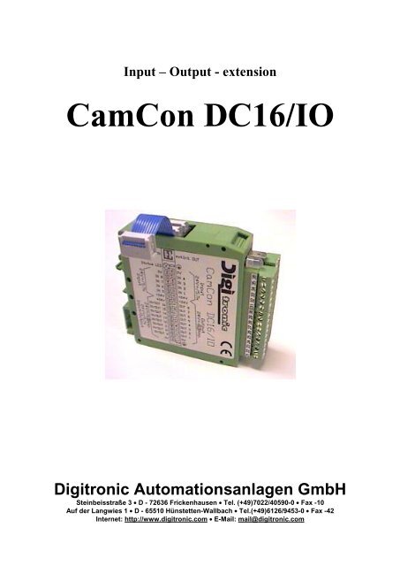
Input – Output - extension<br />
<strong>CamCon</strong> <strong>DC16</strong>/<strong>IO</strong><br />
Digitronic Automationsanlagen GmbH<br />
Steinbeisstraße 3 • D - 72636 Frickenhausen • Tel. (+49)7022/40590-0 • Fax -10<br />
Auf der Langwies 1 • D - 65510 Hünstetten-Wallbach • Tel.(+49)6126/9453-0 • Fax -42<br />
Internet: http://www.digitronic.com • E-Mail: mail@digitronic.com
Digitronic<br />
Automationsanlagen GmbH<br />
Input - Output - extension<br />
<strong>CamCon</strong> <strong>DC16</strong>/<strong>IO</strong><br />
For your attention<br />
This instruction manual relates to the <strong>CamCon</strong> <strong>DC16</strong>/<strong>IO</strong> from 5.1.1998. The company Digitronic<br />
Automationsanlagen GmbH reserves the right to make changes which present an improvement of the<br />
quality or functionality of the device without prior notice. The instruction manual was created with great<br />
care, although it may not be error-proof. We would be grateful for any communication relating to any<br />
errors you may have found.<br />
UP-date<br />
You can also obtain this instruction manual on the Internet at http://www.digitronic.com in the latest<br />
version as PDF file.<br />
Qualified personnel<br />
This device may only be started and operated by qualified staff. By qualified we mean personnel who<br />
are entitled to handle, to earth and to lable devices, systems and power circuits in accordance with the<br />
technology safety standards.<br />
Liability<br />
(1) The supplier is liable for damages caused by himself or by the owner of the rights up to the sum of<br />
the sales price. He is not liable for loss of profits, forfeited savings, intermediate and successive<br />
damages.<br />
(2) The above mentioned limits to liability do not apply to insurance of named characteristics and<br />
damages which were caused deliberately or through negligence.<br />
Protection<br />
The <strong>CamCon</strong> <strong>DC16</strong>/<strong>IO</strong> and this instruction manual are protected by copyright. All rights are reserved.<br />
Neither the <strong>CamCon</strong> <strong>DC16</strong>/<strong>IO</strong>, nor this document may be copied as a whole or partially, photocopied,<br />
reproduced, translated or transferred to electronic media of any kind or into machine readable format<br />
without prior written permission by the company Digitronic Automationsanlagen GmbH.<br />
Note: We have examined the devices of the <strong>CamCon</strong> series for year 2000 compatibility and<br />
have not found any adverse effects on any functions.<br />
Note: <strong>CamCon</strong> is a registered trademark of the company Firma Digitronic<br />
Automationsanlagen GmbH.<br />
Note: The devices of the <strong>CamCon</strong> series comply with the standards for electromagnetic<br />
compatibility: EN 55011, EN 55022, EN 55024 Part 2, EN 50082 Part 2, ENV 50140,<br />
VDE 0843 Part 2, VDE 0843 Part 4, VDE 0871, VDE 0875 Part 3 ("N"),<br />
VDE 0875 Part 11, VDE 0877 Part 2, IEC 801 Part 3, IEC 801 Part 2, IEC 801 Part 4,<br />
IEC 801 Part 5.<br />
(c) Copyright 1992 - 2004 / File: <strong>DC16</strong><strong>IO</strong>E.DOC<br />
Digitronic Automationsanlagen GmbH<br />
Auf der Langwies 1<br />
D-65510 Hünstetten - Wallbach<br />
Tel. (+49)6126/9453-0 Fax. (+49)6126/9453-42<br />
Internet: http://www.digitronic.com<br />
E-Mail: mail@digitronic.com<br />
Issue: Aug. 04 page: 2
Digitronic<br />
Automationsanlagen GmbH<br />
Input - Output - extension<br />
<strong>CamCon</strong> <strong>DC16</strong>/<strong>IO</strong><br />
Content<br />
1. Introduction ..........................................................................................................................................3<br />
2. Assembling ..........................................................................................................................................4<br />
3. Status LED...........................................................................................................................................4<br />
4. Dimensions ..........................................................................................................................................4<br />
5. Electrical connections ..........................................................................................................................5<br />
5.1. Clamping allocation...........................................................................................................................5<br />
5.1.1. Clamping allocation of the voltage supply......................................................................................5<br />
5.1.2. Clamping allocation of the outputs 1 - 8.........................................................................................5<br />
5.1.3. Clamping allocation of the outputs 9 - 16 / inputs 9 - 16................................................................5<br />
5.1.4. Clamping allocation of the inputs 1 - 4...........................................................................................5<br />
5.1.5. Clamping allocation of the inputs 5-8.............................................................................................5<br />
5.2. External interface..............................................................................................................................6<br />
5.2.1. Pin allocation of the external interface IN ......................................................................................6<br />
5.2.2. Pin allocation of the external interface OUT ..................................................................................6<br />
5.2.3. External interface having a cable length from 0.5 to 300m............................................................6<br />
6. Outputs ................................................................................................................................................7<br />
7. Inputs ...................................................................................................................................................7<br />
8. Comissioning .......................................................................................................................................7<br />
9. Technical data......................................................................................................................................8<br />
1. Introduction<br />
The <strong>CamCon</strong> <strong>DC16</strong>/<strong>IO</strong> is used as an input / output extension for the electronic cam-switch<br />
mechanisms of the <strong>CamCon</strong> series. Each <strong>CamCon</strong> <strong>DC16</strong>/<strong>IO</strong> module has got 16 inputs and 16 outputs,<br />
it can be connected by means of the external interface of the <strong>CamCon</strong> <strong>DC16</strong>, 50, 90 or DC115<br />
devices. By a series connection of several <strong>CamCon</strong> <strong>DC16</strong>/<strong>IO</strong> modules it is possible to increase the<br />
total number of inputs and outputs at one Camcon to at maximum 200 inputs and 200 outputs. Thus,<br />
at a <strong>CamCon</strong> <strong>DC16</strong> having 16 outputs and 8 inputs another 11 <strong>CamCon</strong> <strong>DC16</strong>/<strong>IO</strong> modules could be<br />
connected. With 10 <strong>CamCon</strong> <strong>DC16</strong>/<strong>IO</strong> modules, for instance, you have got additionally 176 outputs<br />
and 168 inputs at your disposal. But, please note that the outputs 9 to 16 and the inputs 9 to 16 share<br />
one clamp at the <strong>CamCon</strong> <strong>DC16</strong>/<strong>IO</strong> at the time, so that they can be used either as an output only or as<br />
an input.<br />
Issue: Aug. 04 page: 3
Digitronic<br />
Automationsanlagen GmbH<br />
Input - Output - extension<br />
<strong>CamCon</strong> <strong>DC16</strong>/<strong>IO</strong><br />
2. Assembling<br />
The <strong>CamCon</strong> <strong>DC16</strong>/<strong>IO</strong> input – output extension is locked on an EN carrier bar in the switch cabinet. In<br />
order to avoid the overheating of the module there should be an air gap of 10 mm between the<br />
devices. The earthing clamps shall be connected to the central earth connection point of the mounting<br />
panel on the shortest possible way. By means of the enclosed ten-pole flat cable the external interface<br />
of the <strong>CamCon</strong> <strong>DC16</strong> is connected to the ten-pole pin plug "ext.Int.IN" at the <strong>CamCon</strong> <strong>DC16</strong>/<strong>IO</strong><br />
module. Each other <strong>CamCon</strong> <strong>DC16</strong>/<strong>IO</strong> module is connected to the plug "ext.Int.OUT" by the<br />
respective ten-pole flat cable. Each <strong>CamCon</strong> <strong>DC16</strong>/<strong>IO</strong> module shall be connected with the supply<br />
voltage which amounts to 24VDC +/-20 %. The data line of the <strong>CamCon</strong> <strong>DC16</strong>/<strong>IO</strong> modules are<br />
connected to each other via optical-couplers, thus being free of potentials. For monitoring the data<br />
exchange you should program the safety output of the <strong>CamCon</strong> at the last <strong>CamCon</strong> <strong>DC16</strong>/<strong>IO</strong> module,<br />
because this will switch off in the case of an interruption of the cable connection. All cable connections<br />
should be established in cold state!<br />
3. Status LED<br />
The <strong>CamCon</strong> <strong>DC16</strong>/<strong>IO</strong> module has got a three-coloured status LED:<br />
dark:<br />
green:<br />
red:<br />
orange:<br />
There is no supply voltage.<br />
Indicates an operation without errors.<br />
Indicates that the outputs were switched off due to overload or short circuit.<br />
Indicates that there is no data exchange by a <strong>CamCon</strong> at the moment. The possible reasons<br />
are: the cable length adjusted at the <strong>CamCon</strong> exceeds the admissible limit of 300 metres, the<br />
<strong>CamCon</strong> is switched off or the data exchange is interrupted (e. g. by a cable break). In all<br />
cases all outputs of the <strong>CamCon</strong> <strong>DC16</strong>/<strong>IO</strong> module are set back.<br />
4. Dimensions<br />
Issue: Aug. 04 page: 4
Digitronic<br />
Automationsanlagen GmbH<br />
Input - Output - extension<br />
<strong>CamCon</strong> <strong>DC16</strong>/<strong>IO</strong><br />
5. Electrical connections<br />
Before you begin with wiring, please consult the following chapters: "6. Outputs" on page 7, "7. Inputs"<br />
on page 7.<br />
5.1. Clamping allocation<br />
.<br />
5.1.1. Clamping allocation of the voltage supply<br />
The voltage supply of the device is performed by the voltage supply of the outputs.<br />
Note:<br />
0V clamps 1, 21, 16 and 36 are interconnected.<br />
+24VDC clamps 10, 11, 30 and 31 are interconnected.<br />
5.1.2. Clamping allocation of the outputs 1 - 8<br />
Clamp 1: 0V voltage supply for the outputs 1 - 8<br />
Clamp 2: Output 1<br />
Clamp 3: Output 2<br />
Clamp 4: Output 3<br />
Clamp 5: Output 4<br />
Clamp 6: Output 5<br />
Clamp 7: Output 6<br />
Clamp 8: Output 7<br />
Clamp 9: Output 8<br />
Clamp 10: +24VDC voltage supply for the outputs 1 - 8<br />
5.1.3. Clamping allocation of the outputs 9 - 16 / inputs 9 - 16<br />
The connecting clamps of the outputs 9 - 16 are double used. If, for instance output, 13 is set at the<br />
same time input 13 is activated.<br />
Clamp 21: 0V voltage supply for the outputs / inputs 9 - 16<br />
Clamp 22: Output 9 / Input 9<br />
Clamp 23: Output 10 / Input 10<br />
Clamp 24: Output 11 / Input 11<br />
Clamp 25: Output 12 / Input 12<br />
Clamp 26: Output 13 / Input 13<br />
Clamp 27: Output 14 / Input 14<br />
Clamp 28: Output 15 / Input 15<br />
Clamp 29: Output 16 / Input 16<br />
Clamp 30: +24VDC voltage supply for the outputs / inputs 9 - 16<br />
5.1.4. Clamping allocation of the inputs 1 - 4<br />
Clamp 11: +24VDC voltage supply, connected with the clamps 10, 30 and 31<br />
Clamp 12: Input 1<br />
Clamp 13: Input 2<br />
Clamp 14: Input 3<br />
Clamp 15: Input 4<br />
Clamp 16: 0V reference potential for inputs, connected with the clamps 1, 21 and 36<br />
5.1.5. Clamping allocation of the inputs 5-8<br />
Clamp 31: +24VDC voltage supply, connected with the clamps 10, 11 and 30<br />
Clamp 32: Input 5<br />
Clamp 33: Input 6<br />
Clamp 34: Input 7<br />
Clamp 35: Input 8<br />
Clamp 36: 0V reference potential for inputs, connected with the clamps 1, 21 and 16<br />
Issue: Aug. 04 page: 5
Digitronic<br />
Automationsanlagen GmbH<br />
Input - Output - extension<br />
<strong>CamCon</strong> <strong>DC16</strong>/<strong>IO</strong><br />
5.2. External interface<br />
The data exchange with the <strong>CamCon</strong> cam-switch mechanism is performed via the external interface.<br />
The <strong>CamCon</strong> DAC16 module has got two ten-pole pin plugs, the connections "ext.Int.IN" and<br />
"ext.Int.OUT". The data exchange with the <strong>CamCon</strong> cam-switch mechanism is carried out via<br />
ext.Int.IN. The data exchange with another <strong>CamCon</strong> module (e. g.. <strong>CamCon</strong> DAC16, <strong>CamCon</strong><br />
<strong>DC16</strong>/<strong>IO</strong> or <strong>CamCon</strong> DC91/<strong>IO</strong> and DC92/I respectively) is carried out via ext.Int.OUT. the data<br />
exchange is performed by optical-couplers so that the connection remains free of potentials. By this<br />
connection system a bus system can be established for the most various applications. For connecting<br />
the <strong>DC16</strong>/<strong>IO</strong> module with the <strong>CamCon</strong> <strong>DC16</strong> an approximately 4.5 cm long ten-pole flat cable is<br />
enclosed.<br />
<strong>DC16</strong>/<strong>IO</strong> <strong>DC16</strong> 5.2.1. Pin allocation of the external interface IN<br />
Pin 1,10: not engaged<br />
Pin 4,7: Earth (0V)<br />
Pin 2: RxD -<br />
Pin 3: RxD +<br />
Pin 5: CLK -<br />
Pin 6: CLK +<br />
Pin 8: TxD -<br />
Pin 9: TxD +<br />
5.2.2. Pin allocation of the external interface OUT<br />
Pin 1,4,7,10: not engaged<br />
Pin 2: TxD -<br />
Pin 3: TxD +<br />
Pin 5: CLK -<br />
Pin 6: CLK +<br />
Pin 8: RxD -<br />
Pin 9: RxD +<br />
5.2.3. External interface having a cable length from 0.5 to 300m<br />
The maximum cable length of the external interface is 300 metres. For this purpose a shielded six-pole<br />
data cable with cores twisted in pairs and an adapter cable from the ten-pole flat cable to the nine-pole<br />
DSUB plug are needed. The shielding of this cable shall be placed upon the earth plugs at both sides.<br />
Issue: Aug. 04 page: 6
Digitronic<br />
Automationsanlagen GmbH<br />
Input - Output - extension<br />
<strong>CamCon</strong> <strong>DC16</strong>/<strong>IO</strong><br />
6. Outputs<br />
The <strong>CamCon</strong> <strong>DC16</strong>/<strong>IO</strong> has got 16 short-circuit-proof outputs. They deliver 24V highly active signals<br />
and they are not free of potentials to the supply voltage of the device. They are supplied with +24 V via<br />
the clamps 10 and 30 and with 0 V via the clamps 1 and 21.<br />
At a surrounding temperature of 25°C one output delivers up to 200 mA permanent current. Is the<br />
output overloaded or is there a short circuit, the status LED will emit a red light and at the <strong>CamCon</strong><br />
cam-switch mechanism the fault signal "Off-Err" will occur. The fault signal can be acknowledged by<br />
pressing the<br />
button at the <strong>CamCon</strong> or by switching the voltage supply off and on.<br />
Please, note: The outputs 9 - 16 share the clamps with the inputs 9 - 16.<br />
Note:<br />
For inductive loads the outputs shall be wired with a free-wheeling diode. Contactors or<br />
inductors, which are located in the switch cabinet in the immediate vicinity of the device or<br />
which influence the device or the wiring of the device by their wiring, shall be wired with<br />
commutating elements.<br />
7. Inputs<br />
The <strong>CamCon</strong> <strong>DC16</strong>/<strong>IO</strong> has got 16 inputs. These inputs function with highly active 24 V signals and are<br />
not free of potentials. The reference potential (0V) of the inputs is on clamps 1,16, 21 and 36.<br />
Please, note: The inputs 9 - 16 share the clamps with the outputs 9 - 16.<br />
The input resistance amounts to approx. 5.7 KOhm.<br />
Input circuit:<br />
8. Comissioning<br />
Before switching the device on for the first time, please check the wiring of the device. See chapter "5.<br />
Electrical connections" at page 5. In order to configurate the outputs, please refer to the sub-chapter<br />
“System extension” in the chapter “System adjustment” and to the sub-chapter “SPS configuration”<br />
(Option) in the chapter ”Configuration of the device” in the manual of the cam-switch device.<br />
Issue: Aug. 04 page: 7
Digitronic<br />
Automationsanlagen GmbH<br />
Input - Output - extension<br />
<strong>CamCon</strong> <strong>DC16</strong>/<strong>IO</strong><br />
9. Technical data<br />
Indication.............................................................three-colour status LED<br />
Number of outputs ..............................................16,<br />
whereby the outputs 9 – 16 are<br />
connected with the inputs 9 - 16.<br />
Number of inputs.................................................16,<br />
whereby the inputs 9 – 16 are<br />
connected with the outputs 9 - 16.<br />
Length of the connecting cable<br />
between <strong>CamCon</strong> and <strong>CamCon</strong> <strong>DC16</strong>/<strong>IO</strong>..........max. 300 m.<br />
Supply voltage.....................................................24VDC ±20 %<br />
Output voltage.....................................................24VDC, positively connecting<br />
Output current .....................................................0,2A per output, short-circuit-proof<br />
Current consumption...........................................approx. 80mA without load.<br />
Connections for:<br />
Voltage supply and outputs ................................via plug-in screw clamps IP20<br />
Inputs .................................................................via plug-in screw clamps IP20<br />
Assembly.............................................................convenient snap-on assembly; carrier bar according to<br />
EN 50 022, can be put together with an air gap of 10<br />
mm.<br />
Dismantling .........................................................by pulling back the snap lock.<br />
Dimensions .........................................................Please see chapter 4. Dimensions at page 4.<br />
International protection........................................The case fulfils IP20.<br />
Operation temperature........................................0°C ... + 50° C<br />
Weight.................................................................approx. 150 g<br />
Issue: Aug. 04 page: 8