CamCon DC60/61
Digital Cam Controller CamCon DC60/61
Digital Cam Controller CamCon DC60/61
- No tags were found...

Create successful ePaper yourself
Turn your PDF publications into a flip-book with our unique Google optimized e-Paper software.
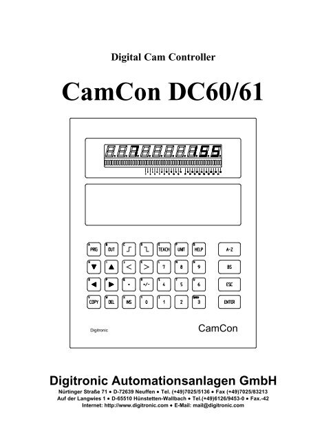
Digital Cam Controller<br />
<strong>CamCon</strong> <strong>DC60</strong>/<strong>61</strong><br />
Digitronic<br />
<strong>CamCon</strong><br />
Digitronic Automationsanlagen GmbH<br />
Nürtinger Straße 71 • D-72639 Neuffen • Tel. (+49)7025/5136 • Fax (+49)7025/83213<br />
Auf der Langwies 1 • D-65510 Hünstetten-Wallbach • Tel.(+49)<strong>61</strong>26/9453-0 • Fax.-42<br />
Internet: http://www.digitronic.com • E-Mail: mail@digitronic.com
Digital Cam Controller<br />
<strong>CamCon</strong> <strong>DC60</strong>/L<br />
Digitronic<br />
Automationsanlagen GmbH<br />
Notification<br />
This booklet corresponds with the state of the <strong>CamCon</strong> <strong>DC60</strong>/<strong>61</strong> from June 10th 1996. The company<br />
Digitronic Automationsanlagen GmbH has reserved all rights to alterations without prior notice, if these are<br />
followed by an inprovement of the quality or the functioning of this piece of equipment.<br />
The instruction booklet has been constructed exercising maximum care, but mistakes are not exactly out of<br />
the question. We are grateful for any hints concerning possible mistakes in the booklet.<br />
Qualified personal only<br />
Commissioning and operation of the device may only be carried out by qualified personal. Qualified personal<br />
are persons, authorized with commissioning, grounding and labeling devices, systems and electrical circuits<br />
according to the applicable standards of security<br />
LIABILITY<br />
(1) The salesperson is liable for any damages for which he or the rightful owner is responsible up to the<br />
amount of the actual salesprice. Liability concerning missed profits, failed-to-appear savings, indirect<br />
damages and consequential damage is excluded.<br />
(2) The liability restrictions above are not valid concerning assured characteristics and damages, which are<br />
caused by intention or coarse negligence.<br />
PROTECTION<br />
<strong>CamCon</strong> <strong>DC60</strong>/<strong>61</strong> and this booklet are protected by copyright. All rights are reserved. Neither <strong>CamCon</strong><br />
<strong>DC60</strong>/<strong>61</strong> nor this document may be partly or wholly copied, photocopied, reproduced, translated or<br />
transfered onto any electrical media or forms which are readable by machine without prior, written permit<br />
through the company Digitronic Automationsanlagen GmbH.<br />
Note:<br />
Note:<br />
Note:<br />
The products of Digitronic are so well constructed that they will not be effected by the<br />
millenium.<br />
<strong>CamCon</strong> is a registered trademark of the company Firma Digitronic Automationsanlagen<br />
GmbH.<br />
The cam controllers of the <strong>CamCon</strong> series fullfill the norms regarding electromagnetic<br />
emmission: EN 55011, EN 55022, EN 55024 Part 2, EN 50082 Part 2, ENV 50140,<br />
VDE 0843 Part 2, VDE 0843 Part 4, VDE 0871, VDE 0875 Part 3 ("N"),<br />
VDE 0875 Part 11, VDE 0877 Part 2, IEC 801 Part 3, IEC 801 Part 2, IEC 801 Part 4,<br />
IEC 801 Part 5.<br />
(c) Copyright 1992 - 2000 / File: DC_L_E.DOC<br />
Digitronic Automationsanlagen GmbH<br />
Auf der Langwies 1<br />
D-65510 Hünstetten - Wallbach<br />
Tel. (+49)<strong>61</strong>26/9453-0 Fax. (+49)<strong>61</strong>26/9453-42<br />
Internet: http://www.digitronic.com<br />
E-Mail: mail@digitronic.com<br />
Page: 2 Version: April 00
Digitronic<br />
Automationsanlagen GmbH<br />
Digital Cam Controller<br />
<strong>CamCon</strong> <strong>DC60</strong>/L<br />
Table of contents<br />
1. Introduction ......................................................................................................................................5<br />
2. Principle of function...........................................................................................................................6<br />
3. Mechanical installation instructions......................................................................................................7<br />
4. Electrical connections ........................................................................................................................8<br />
4.1. The encoder ..................................................................................................................................8<br />
4.2. The external program selection .......................................................................................................8<br />
4.3. The serial interface.........................................................................................................................8<br />
4.4. The outputs ...................................................................................................................................8<br />
4.5. Precautions to be taken during welding operations............................................................................9<br />
4.6. The pin allocation of the single axis compact unit ............................................................................10<br />
5. Multi axis systems...........................................................................................................................11<br />
5.1. Construction of a dual controller system.........................................................................................11<br />
5.2. Construction of a tripple controller system......................................................................................12<br />
5.3. Upgrading multi axis units..............................................................................................................13<br />
5.4. Ordering the new axis...................................................................................................................13<br />
5.5. Adjustment of the board to the axis number....................................................................................13<br />
5.6. The option program change ..........................................................................................................14<br />
5.7. Opening the multi axis device ........................................................................................................14<br />
5.8. Wiring of the new axes .................................................................................................................15<br />
5.9. Pin allocation in a multi axis system ...............................................................................................15<br />
6. The user terminal ............................................................................................................................17<br />
6.1. Outline of the user terminal ...........................................................................................................17<br />
6.2. The LED display unit.....................................................................................................................18<br />
6.2.1. The seven-segment display........................................................................................................18<br />
6.2.2. The LED display bar..................................................................................................................18<br />
6.3. The Liquid Crystal Display (LCD)...................................................................................................18<br />
6.4. The speed and position display .....................................................................................................18<br />
6.5. The keyboard ..............................................................................................................................19<br />
6.6. Outline of the key functions ...........................................................................................................19<br />
7. Commissioning................................................................................................................................21<br />
8. Programming ..................................................................................................................................21<br />
8.1. General information......................................................................................................................21<br />
8.2. <strong>CamCon</strong> main menu .....................................................................................................................21<br />
8.3. The user key................................................................................................................................22<br />
8.4. Complete deletion ........................................................................................................................22<br />
8.5. The system constants...................................................................................................................23<br />
8.5.1. Language .................................................................................................................................23<br />
8.5.2. Real encoder resolution .............................................................................................................24<br />
8.5.3. Electronic gear and change of the rotation direction .....................................................................24<br />
8.5.4. Zero point, Offset......................................................................................................................24<br />
8.5.5. Speed factor.............................................................................................................................25<br />
8.6. Program selection........................................................................................................................26<br />
Version: April 00 Page: 3
Digital Cam Controller<br />
<strong>CamCon</strong> <strong>DC60</strong>/L<br />
Digitronic<br />
Automationsanlagen GmbH<br />
8.7. Programming cams ......................................................................................................................26<br />
8.7.1. Output selection........................................................................................................................26<br />
8.7.2. Giving outputs names ................................................................................................................26<br />
8.7.3. Input of cams ............................................................................................................................27<br />
8.7.4. Programming additional cams on an output..................................................................................27<br />
8.7.5. Cam search..............................................................................................................................27<br />
8.7.6. Editing cams .............................................................................................................................27<br />
8.7.7. Optimizing cams........................................................................................................................28<br />
8.7.8. The "TEACH IN" function............................................................................................................28<br />
8.7.9. Deletion....................................................................................................................................28<br />
8.7.9.1. Deletion of a programmed cam................................................................................................28<br />
8.7.9.2. Deletion of a programmed output (cam track)...........................................................................29<br />
8.7.9.3. Deletion of a program.............................................................................................................29<br />
8.7.10. Exit cam programming .............................................................................................................29<br />
8.7.11. Example for cam programming .................................................................................................30<br />
8.7.11.1. First cam programming .........................................................................................................30<br />
8.7.11.2. Programming additional cams on an output .............................................................................31<br />
8.8. Automatic display (output display) .................................................................................................31<br />
8.8.1. Program selection .....................................................................................................................31<br />
9. Disruptions .....................................................................................................................................32<br />
9.1. I-ERR (Actual position error).........................................................................................................32<br />
9.2. A-ERR (Output error) ...................................................................................................................32<br />
9.3. <strong>CamCon</strong> does not save data.........................................................................................................32<br />
10. watch doc.....................................................................................................................................33<br />
11. Technichal data of the <strong>CamCon</strong>......................................................................................................34<br />
12. Key word table .............................................................................................................................35<br />
Page: 4 Version: April 00
Digitronic<br />
Automationsanlagen GmbH<br />
Digital Cam Controller<br />
<strong>CamCon</strong> <strong>DC60</strong>/L<br />
1. Introduction<br />
Electrical cam switch units have been used successfully by the industry for a long time.The experiences<br />
which have been collected in close co-operation during these years have been considered during the<br />
development of the <strong>CamCon</strong>. The result is a compact digital cam switch unit which ownes a maximum of<br />
user comfort and reliability.<br />
The following characteristics distinguish the <strong>CamCon</strong>:<br />
* Experienced and reliable hardware<br />
* Big seven-segment display for program, position and speed<br />
* Multi language LC-Display with good contrast 8 lines, 40 characters<br />
* Front panel with accoustic buttons<br />
* Compact construction<br />
* In/Outputs with separate potential<br />
* Display status of all 32 outputs at the same time<br />
* As many cams per output as programmable<br />
* Optimizing of the switching points while the machine operates<br />
* Digital speed display with programmable factor<br />
* Integrated electronic gear with free programmable gear factor<br />
* Optionally upgradable to 64 outputs<br />
* In steps of 1 ms adjustable compensation of the mechanical dead time of switching devices<br />
* Voltage supply 24V DC +/- 20%<br />
Cam controllers are being used everywhere where switching procedures are being periodically repeated.<br />
Digital cam controllers replace mechanical ones optimally and furthermore offer other advantages, for<br />
example:<br />
* Simplification of assembly and adjustment procedures<br />
* Reproducible justage<br />
* Standardization for all possible ranges of operation<br />
* Reliability<br />
Version: April 00 Page: 5
Digital Cam Controller<br />
<strong>CamCon</strong> <strong>DC60</strong>/L<br />
Digitronic<br />
Automationsanlagen GmbH<br />
2. Principle of function<br />
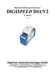
Fig.: Priciple of function of a cam controller<br />
For a better understanding of the function of a cam switch unit its principle is presented here. It has 3<br />
outputs containing the following cams:<br />
Output 1 Cam 1: Activation point 60° Deactivation point 85°<br />
Cam 2: Activation point 95° Deactivation point 145°<br />
Cam 3: Activation point 325° Deactivation point 355°<br />
Output 2 Cam 1: Activation point 5° Deactivation point 20°<br />
Cam 2: Activation point 95° Deactivation point 145°<br />
Output 3 Cam 1: Activation point 30° Deactivation point 85°<br />
The 3 as beds presented progressions of the output signals occur, if the 3 cam plates turn anticlockwise<br />
past a sensor, which scans the cams on the 0° axis.<br />
The duration of the switching on of a mechanical cam switch unit, i.e. the range between the on and off<br />
position, is determined by the length of the cams. The length and the position of the cams can only be<br />
limitedly varied, which aditionally demands a relatively high mechanical and chronological expenditure. With<br />
the <strong>CamCon</strong>, these adjustments are realized within a fraction of a second, besides the number of the cams<br />
per bed is optional. An encoder, which has been connected to the device reports the position to the<br />
<strong>CamCon</strong>. The <strong>CamCon</strong> compares this with the programmed (de)activation points from all the outputs. If a<br />
position appears in a range of a programmed (de)activation point (cams), all affected outputs will be<br />
switched.<br />
Page: 6 Version: April 00
Digitronic<br />
Automationsanlagen GmbH<br />
Digital Cam Controller<br />
<strong>CamCon</strong> <strong>DC60</strong>/L<br />
3. Mechanical installation instructions<br />
To incase the front plate, the <strong>CamCon</strong> is inserted into an opening (as shown in the drawing).<br />
label<br />
grounding pins<br />
connection clip<br />
plug input<br />
switch board door<br />
The thickness of the switch board<br />
door should not exceed 3mm !<br />
CUTOUT PER<br />
- connect no more than one wire to each pin<br />
- do not allocate voltage to the outputs<br />
- connect the grounding pin on the back of the Camcon with the switch board encasement<br />
- connect all mantled cables (cable of the encoder, the voltage supply or the outputs) in the form<br />
of a star<br />
- make all cable connections in a cold state<br />
- lead controlling wires to the <strong>CamCon</strong> separat from power current lines<br />
- never enter or remove a plug under current<br />
Version: April 00 Page: 7
Digital Cam Controller<br />
<strong>CamCon</strong> <strong>DC60</strong>/L<br />
Digitronic<br />
Automationsanlagen GmbH<br />
- operate only under the VDE regulations<br />
- clean foil keyboard only without plug with water or spiritus<br />
- do not damage foil keyboard with sharp or edged objects<br />
- work only according to antistatic regulations<br />
- watch <strong>CamCon</strong> during assembly to prevent overheating<br />
- maximum temperature of the operation environment is 55°C<br />
- cold state storing temperature: -15°C to +75°C<br />
- maximum humidity 85%<br />
4. Electrical connections<br />
To prevent disruptions, use separate power supplies for CPU /control unit and the outputs. The grounding<br />
clip of <strong>CamCon</strong> has to be connected at the grounding point of the encasement.<br />
4.1. The encoder<br />
The voltage supply of the encoder is internally connected to the voltage supply of the outputs. If the supply<br />
voltage is connected to the outputs, the encoder is also supplied. The data transfer from the encoder to the<br />
<strong>CamCon</strong> takes place through a bidirectional RS422 interface. The data protocol corresponds with the<br />
Stegmann SSI Norm.<br />
Attention: It is not allowed to plug the encoder into the <strong>CamCon</strong> while voltage is connected,<br />
because the encoder runs with 24V, the data connection with 5V!<br />
4.2. The external program selection<br />
It is possible to change the programs of <strong>CamCon</strong> via exernal inputs. The program number has to be<br />
connected on the inputs in a binary code. Then a pulse with a minimal length of 20ms at the program start<br />
input changes the program in the <strong>CamCon</strong> online.<br />
Using <strong>CamCon</strong> with an SSI data input, it is possible to select all 128 programs.<br />
4.3. The serial interface<br />
The serial port is for connecting the <strong>CamCon</strong> to an external PC for changing datas or programming<br />
the <strong>CamCon</strong> with a communication software (for example DIGISOFT). It is also available to store <strong>CamCon</strong><br />
programs on PCs hard disk.<br />
Multi controller systems use the serial port to connect all the systems.<br />
4.4. The outputs<br />
The outputs are short circuit proof. If all outputs are switched on, you may only extract up to 40mA per<br />
output in full temperature range, or the device switches off with an error message. If you need a higher<br />
output power, you should know that the outputs 1, 3, 5 etc. up to 15, the outputs 2, 4, 6, etc up to 16, the<br />
outputs 17,19,21 etc up to 31 and the outputs 16, 18, 20 etc up to 32 form groups. Within this 4 groups<br />
360mA permanent current are available at 50°C of surrounding temperature, at 25°C of surrounding<br />
temperature it increases to 500mA of permanent current. This output current can be distributed as desired<br />
within a group, as long as the output current of a single output does not exceed 300mA.<br />
Page: 8 Version: April 00
Digitronic<br />
Automationsanlagen GmbH<br />
Digital Cam Controller<br />
<strong>CamCon</strong> <strong>DC60</strong>/L<br />
Attention: With inductive loads the outputs have to be switched with free wheeling diodes.<br />
4.5. Precautions to be taken during welding operations<br />
Attention: For the duration of welding operations carried out at the machine, the connecting<br />
wires concerning the data exchange from the measuring system to the <strong>CamCon</strong><br />
and the power supply as well as the grounding connections and inputs and<br />
outputs have to be separated from the <strong>CamCon</strong>.<br />
Version: April 00 Page: 9
Digital Cam Controller<br />
<strong>CamCon</strong> <strong>DC60</strong>/L<br />
Digitronic<br />
Automationsanlagen GmbH<br />
4.6. The pin allocation of the single axis compact unit<br />
Pin 1: 0V for encoder<br />
Pin 2: Data A or +<br />
Pin 3: Data B or -<br />
Pin 4: Clock A or +<br />
Pin 5: Clock B or -<br />
Pin 6: +24V DC for encoder<br />
Pin 7: 0V supply<br />
Pin 8: Prog.-No. 1<br />
Pin 9: Prog.-No. 2<br />
Pin 10: Prog.-No. 4<br />
Pin 11: Prog.-No. 8<br />
Pin 12: Prog.-No.16<br />
Pin 13: Prog.-No.32<br />
Pin 14: Prog.-No.64<br />
Pin 15: Program start<br />
Pin 16: 0V voltage supply for CPU and encoder<br />
Pin 17: 0V voltage supply for CPU and encoder<br />
Pin 18: +24V DC 0V voltage supply for CPU and encoder<br />
Pin 19: +24V DC for DIGIPROG or DIGITERM<br />
Pin 20: RxD from RS232<br />
Pin 21: 0V from supply<br />
Pin 22: 0V from supply<br />
Pin 23: TxD from RS232<br />
The outputs are connected on a 40 poled plug and have the following allocation:<br />
Pin 1 - Output 2 Pin 11 - Output 12 Pin 21 - Output 18 Pin 31 - Output 28<br />
Pin 2 - Output 1 Pin 12 - Output 11 Pin 22 - Output 17 Pin 32 - Output 27<br />
Pin 3 - Output 4 Pin 13 - Output 14 Pin 23 - Output 20 Pin 33 - Output 30<br />
Pin 4 - Output 3 Pin 14 - Output 13 Pin 24 - Output 19 Pin 34 - Output 29<br />
Pin 5 - Output 6 Pin 15 - Output 16 Pin 25 - Output 22 Pin 35 - Output 32<br />
Pin 6 - Output 5 Pin 16 - Output 15 Pin 26 - Output 21 Pin 36 - Output 31<br />
Pin 7 - Output 8 Pin 17 - +24V Pin 27 - Output 24 Pin 37 - +24V<br />
Pin 8 - Output 7 Pin 18 - +24V Pin 28 - Output 23 Pin 38 - +24V<br />
Pin 9 - Output 10 Pin 19 - 0V Pin 29 - Output 26 Pin 39 - 0V<br />
Pin 10 - Output 9 Pin 20 - 0V Pin 30 - Output 25 Pin 40 - 0V<br />
Page: 10 Version: April 00
Digitronic<br />
Automationsanlagen GmbH<br />
Digital Cam Controller<br />
<strong>CamCon</strong> <strong>DC60</strong>/L<br />
5. Multi axis systems<br />
It is possible to realize a multi controller sytem with 64 single devices. This network has the following<br />
advantages:<br />
* programming with only one programming terminal<br />
* low costs for one single device<br />
* easy handling<br />
* small housings<br />
The programming have to be done separate for each system.<br />
The pictures shows you the construction of a dual controller system and a tripple controller system, with the<br />
possibility to use on each single system one encoder. The wiring of the serial port is completly ready and<br />
have not to be changed. While fixing-up it is nessecary to note the dimensions of the device.<br />
5.1. Construction of a dual controller system<br />
Encoder<br />
Inputs for the external<br />
program selection<br />
Voltage supply<br />
Wiring of the<br />
serial interface<br />
(made in the plant)<br />
Outputs<br />
Unit or axis No. 2<br />
Unit or axis No. 1<br />
DIGITERM<br />
Version: April 00 Page: 11
Digital Cam Controller<br />
<strong>CamCon</strong> <strong>DC60</strong>/L<br />
Digitronic<br />
Automationsanlagen GmbH<br />
5.2. Construction of a tripple controller system<br />
Encoder<br />
Inputs for the external<br />
program selection<br />
Voltage supply<br />
Wiring of the<br />
serial interface<br />
(made in the plant)<br />
Outputs<br />
Unit or axis No. 3<br />
Unit or axis No. 2<br />
Unit or axis No. 1<br />
DIGITERM<br />
If more than 3 systems are used, calculate 27mm distance for each next sytem.<br />
Page: 12 Version: April 00
Digitronic<br />
Automationsanlagen GmbH<br />
Digital Cam Controller<br />
<strong>CamCon</strong> <strong>DC60</strong>/L<br />
5.3. Upgrading multi axis units<br />
To upgrade a multi axis unit from 1 axis to 2, 3 or 4 axis , you have to follow the next procedure.<br />
5.4. Ordering the new axis<br />
The order discription is as follows: "DC71 / Type / Axis number"<br />
Example: "DC71 / I / 3"<br />
The single parameters of the discription example have the following functions:<br />
DC - <strong>CamCon</strong><br />
71 - New axis (for upgrading)<br />
/ I - Incremental data input<br />
/ 3 - Axis number 3<br />
You have to specify the type of board and the number of the axis (see order discription). This information is<br />
used to label the pins and set the unit number.<br />
Also part of the equippment are:<br />
- the board<br />
- labels for the pin numbers (if no axis number is specified, the pins are not labeled in the plant)<br />
- the additional encasement ring<br />
- 5 spacing bolts M4 x 25mm<br />
5.5. Adjustment of the board to the axis number<br />
On the boards of the <strong>CamCon</strong> <strong>61</strong>/71 series are DIP switches with 8 poles or 8-segment soldering bridges<br />
to set the number of the axis. The first axis in the device bears the number 1, the second axis the number 2<br />
and so on. You may not assign the same number to several axis on the same board ! ! ! By<br />
connecting the axis modules via the serial interface and the setting of the unit number, the programming<br />
device for the multi axis system (DIGITERM/DIGIPROG) can differentiate between the different axis.<br />
for option program change set to OFF<br />
always set to ON<br />
UNIT or ACHSE 32<br />
UNIT or ACHSE 16<br />
UNIT or ACHSE 8<br />
UNIT or ACHSE 4<br />
UNIT or ACHSE 2<br />
UNIT or ACHSE 1<br />
Units of the newer generations have an 8-<br />
segment soldering bridge for the adjustment of<br />
the unit number, instead of a DIP switch with 8<br />
poles. Here you just close the desired soldering<br />
bridge with your soldering iron, that has to be<br />
set to ON according to the drawing below.<br />
Contrary to the versions with the DIP switch,<br />
the functions are inverted.<br />
new generation<br />
old generation<br />
Version: April 00 Page: 13
Digital Cam Controller<br />
<strong>CamCon</strong> <strong>DC60</strong>/L<br />
Digitronic<br />
Automationsanlagen GmbH<br />
5.6. The option program change<br />
<strong>CamCon</strong>s <strong>61</strong>/71 with 2 or more axes have the ability to change the programs of all axes simultaneously.<br />
This is done with DIP switch No. 8 (or soldering bridge segment No. 8). If it is set to OFF (ON for a<br />
soldering bridge segment), the program of this axis is changed, when the program of another axis is<br />
changed via the keyboard.<br />
This option is only available, if all components of the <strong>CamCon</strong> <strong>61</strong>/71 are equipped with software from at<br />
least Febuary 5th 1993 !<br />
If the communication via the serial interface was not possible, the unit displays "P-ERR" after one second,<br />
and the axis goes into the error mode (all outputs switched off).<br />
5.7. Opening the multi axis device<br />
- remove all plugs from the device<br />
- open the lid by unscrewing the top nuts<br />
- remove the upper spacing bolts (M4 x 24 mm)<br />
- fasten the new bolts (M4 x 25 mm) lightly<br />
- insert the new board<br />
- insert the new device ring<br />
- to install another axis, repeat the installation procedures above<br />
- now fasten the old spacing bolts (M4 x 24 mm) again<br />
- put the lid back on and secure it again with screws, notch plates and nuts.<br />
<strong>CamCon</strong> <strong>61</strong> <strong>CamCon</strong> 71<br />
Lid<br />
Bolt<br />
UNIT or AXIS 5<br />
Bolt<br />
UNIT or AXIS 4<br />
Bolt<br />
UNIT or AXIS 3<br />
Bolt<br />
UNIT or AXIS 2<br />
Bolt<br />
UNIT ore AXIS 1<br />
Bolt<br />
DIGITERM<br />
Front plate<br />
Lid<br />
UNIT or AXIS 6<br />
UNIT or AXIS 5<br />
UNIT or AXIS 4<br />
UNIT or AXIS 3<br />
UNIT or AXIS 2<br />
UNIT or AXIS 1<br />
Bottom plate<br />
Bolt<br />
Bolt<br />
Bolt<br />
Bolt<br />
Bolt<br />
Bolt<br />
Page: 14 Version: April 00
Digitronic<br />
Automationsanlagen GmbH<br />
Digital Cam Controller<br />
<strong>CamCon</strong> <strong>DC60</strong>/L<br />
5.8. Wiring of the new axes<br />
Plug in the PINs with continued numbers in the <strong>CamCon</strong>. Wiring have to be done as shown in the folllowing<br />
picture. If there used less than 6 systems, the wire from PIN 143 must be disconnected and must be new<br />
connected as followed:<br />
- at 5 Systems => PIN 120<br />
- at 4 Systems => PIN 97<br />
- at 3 Systems => PIN 74<br />
- at 2 Systems => PIN 51<br />
- at 1 System => PIN 28<br />
5.9. Pin allocation in a multi axis system<br />
The values in ( ) are for units or axes 2,3,4...<br />
Pin 1: 0V supply<br />
Pin 2: 0V supply<br />
Pin 3: +24V DC supply<br />
Pin 4: +24V DC supply<br />
Pin 5: RxD data receive pin of the RS232<br />
Pin 6: 0V from supply<br />
Pin 7: 0V from supply<br />
Pin 8: TxD Data send pin of the RS232<br />
UNIT or AXIS No. 6<br />
UNIT or AXIS No. 5<br />
UNIT or AXIS No. 4<br />
UNIT or AXIS No. 3<br />
UNIT or AXIS No. 2<br />
UNIT or AXIS No. 1<br />
DIGITERM or DIGIPROG<br />
Pin 9 (32,55,78...): 0V for encoder<br />
Pin 10 (33,56,79...): Data A or +<br />
Pin 11 (34,57,80...): Data B or -<br />
Pin 12 (35,58,81...): Clock A or +<br />
Pin 13 (36,59,82...): Clock B or -<br />
Pin 14 (37,60,83...): +24V DC for encoder<br />
Version: April 00 Page: 15
Digital Cam Controller<br />
<strong>CamCon</strong> <strong>DC60</strong>/L<br />
Digitronic<br />
Automationsanlagen GmbH<br />
Pin 15 (38,<strong>61</strong>,84...): 0V supply<br />
Pin 16 (39,62,85...): Prog.-No. 1<br />
Pin 17 (40,63,86...): Prog.- No. 2<br />
Pin 18 (41,64,87...): Prog.- No. 4<br />
Pin 19 (42,65,88...): Prog.-No. 8<br />
Pin 20 (43,66,89...): Prog.-No. 16<br />
Pin 21 (44,67,90...): Prog.-No. 32<br />
Pin 22 (45,68,91...): Prog.-No. 64<br />
Pin 23 (46,69,92...): Program start<br />
Pin 24 (47,70,93...): 0V voltage supply for CPU and encoder<br />
Pin 25 (48,71,94...): 0V voltage supply for CPU and encoder<br />
Pin 26 (49,72,95...): +24V DC voltage supply for CPU and encoder<br />
Pin 27 (50,73,96...): +24V DC for DIGIPROG<br />
Pin 28 (51,74,97...): RxD from RS232<br />
Pin 29 (52,75,98...): 0V from supply<br />
Pin 30 (53,76,99...): 0V from supply<br />
Pin 31 (54,77,100...): TxD from RS232<br />
The outputs are connected on a plug with 40 poles and have the following allocation:<br />
Pin 1 - Output 2 Pin 11 - Output 12 Pin 21 - Output 18 Pin 31 - Output 28<br />
Pin 2 - Output 1 Pin 12 - Output 11 Pin 22 - Output 17 Pin 32 - Output 27<br />
Pin 3 - Output 4 Pin 13 - Output 14 Pin 23 - Output 20 Pin 33 - Output 30<br />
Pin 4 - Output 3 Pin 14 - Output 13 Pin 24 - Output 19 Pin 34 - Output 29<br />
Pin 5 - Output 6 Pin 15 - Output 16 Pin 25 - Output 22 Pin 35 - Output 32<br />
Pin 6 - Output 5 Pin 16 - Output 15 Pin 26 - Output 21 Pin 36 - Output 31<br />
Pin 7 - Output 8 Pin 17 - +24V Pin 27 - Output 24 Pin 37 - +24V<br />
Pin 8 - Output 7 Pin 18 - +24V Pin 28 - Output 23 Pin 38 - +24V<br />
Pin 9 - Output 10 Pin 19 - 0V Pin 29 - Output 26 Pin 39 - 0V<br />
Pin 10 - Output 9 Pin 20 - 0V Pin 30 - Output 25 Pin 40 - 0V<br />
Page: 16 Version: April 00
Digitronic<br />
Automationsanlagen GmbH<br />
Digital Cam Controller<br />
<strong>CamCon</strong> <strong>DC60</strong>/L<br />
6. The user terminal<br />
6.1. Outline of the user terminal<br />
Digitronic<br />
<strong>CamCon</strong><br />
Version: April 00 Page: 17
Digital Cam Controller<br />
<strong>CamCon</strong> <strong>DC60</strong>/L<br />
Digitronic<br />
Automationsanlagen GmbH<br />
6.2. The LED display unit<br />
6.2.1. The seven-segment display<br />
The <strong>CamCon</strong> LED display with 10 big digits (13mm) garanties a good view to the values from a few meters<br />
distance. On the right side the speed or the position of the encoder is readable, on the left side the actual<br />
program number.<br />
6.2.2. The LED display bar<br />
Under the LED 7-segment display there is a LED display bar, where the user can read the status of all<br />
outputs on the same time.<br />
6.3. The Liquid Crystal Display (LCD)<br />
Under the LED-Display unit there is a LC-Text Display with 8 lines x 40 characters.<br />
The contrast of the LCD can be adjsuted with the keys H and I . Via the keys O and P you can set<br />
the basic parameters of the contrast.<br />
Attention: With multi axis systems, you can only adjust the contrast after having pressed the<br />
F<br />
UNIT<br />
key.<br />
The top line of the LC-display displays the status of the <strong>CamCon</strong>:<br />
"Unit" = unit number (multi axis system)<br />
"Prg" = program number (0-127)<br />
"Speed" = speed with rotation direction<br />
"Act" = current position of the machine<br />
In the second line the selected menues are displayed, on the right side a possible error-message is shown.<br />
6.4. The speed and position display<br />
On the LC-Display the program number, the speed and the actual position are displayed at the same time.<br />
If you are in "main menu" or in the "automatic menu", speed and current position are displayed in upper<br />
righthand corner of the LCD. The 7-segment display then shows the speed and program number. If you<br />
select the menu points "2 Programming", "3 Operating parameters" or "4 Dead Time Compensation", the 7-<br />
segment display automatically switches to the position display.<br />
With Multi-controller systems the change between the displays (speed to position) is possible by pressing<br />
the F UNIT<br />
, followed by the<br />
A<br />
PRG<br />
key. By pressing the two keys at once, you return to the speed display.<br />
Page: 18 Version: April 00
Digitronic<br />
Automationsanlagen GmbH<br />
Digital Cam Controller<br />
<strong>CamCon</strong> <strong>DC60</strong>/L<br />
6.5. The keyboard<br />
The plastic foil keyboard is the most important functioning group of the front plate of the <strong>CamCon</strong>. All<br />
adjustable functions are set via keyboard. It consists of an alphabetic key block as well as different function<br />
keys.<br />
The keyboard is non-sensitive towards dirt and is solvent resisting. The keys have a noticable action point<br />
for the tactile feedback, as well as an acoustic input acknowledgement.<br />
6.6. Outline of the key functions<br />
key for selecting a desired program<br />
this key has no function at this time<br />
input for additional cams on the outputs / cam tracks<br />
you enter the activation point of a cam with this key<br />
you enter the deactivation point of a cam with this key<br />
By pressing this key, you can initiate the following functions in a multi axis<br />
system: input of unit (axis) numbers, change the 7-segment display from<br />
"Speed" and "Prg" to "Position" and adjust the contrast setting of the LCD.<br />
Cursor movement downwards (selecting the next menu point) or contrast<br />
adjustment of the LCD<br />
Cursor movement upwards (selecting the previous menu point) or contrast<br />
adjustment of the LCD<br />
Cursor movement to the left (selecting the previous menu point) or basic<br />
adjustment of the contrast<br />
Cursor movement to the right (selecting the next menu point) or basic<br />
adjustment of the contrast<br />
Version: April 00 Page: 19
Digital Cam Controller<br />
<strong>CamCon</strong> <strong>DC60</strong>/L<br />
Digitronic<br />
Automationsanlagen GmbH<br />
lowers input values<br />
raises input values<br />
ASCII-Character, no decimal point!<br />
changes the algebraic signs<br />
this key has no function at this time<br />
delete cams and single outputs<br />
help function is not implemented yet<br />
confirm key<br />
breaks off functions and leaves the current menus, to return to the next highest<br />
menu<br />
deletes any previously entered character<br />
You can use this key to label your cams. When this key is pressed the small<br />
letters on the upper lefthand corner of the small keys become active.<br />
Page: 20 Version: April 00
Digitronic<br />
Automationsanlagen GmbH<br />
Digital Cam Controller<br />
<strong>CamCon</strong> <strong>DC60</strong>/L<br />
7. Commissioning<br />
Before activating the unit for the first time, please check the wiring of the device. (see chapter "Pin<br />
allocation").<br />
Attention:<br />
With induced loads the outputs have to be switched with a freewheeling diode.<br />
Covers or inductivities very close to the device inside the switchboard have to be<br />
switched with a deletion unit as do those that are wired to or influence the wiring<br />
of the device.<br />
After being switched on the <strong>CamCon</strong> will generate a short tone. After a successful installation of the<br />
system, the standard display (the current program number, the position and the speed, as well as a<br />
possible error message) is displayed. Once the system registers are brought in accord to the measuring<br />
system and it is wired correctly, there should be no further error messages.<br />
8. Programming<br />
8.1. General information<br />
The programming of the <strong>CamCon</strong> happens 'online', meaning that all changes made by you are in the<br />
programming menus are carried over into the RAM memory after being confirmed and thus directly influence<br />
the switching processes.<br />
Attention: If you do not leave a menu point after having made and confirmed an input of<br />
parameters, the new settings have not been written into the longterm memory<br />
(EEPROM), but still is only in the RAM memory. If the supply voltage is<br />
disrupted, the programming is lost. Only when you leave the menu point by<br />
pressing the<br />
memory.<br />
ESC<br />
key, the new parameters are secured into the longterm<br />
8.2. <strong>CamCon</strong> main menu<br />
After having connected the supply voltage, the <strong>CamCon</strong> automatically switches to its main menu displayed<br />
below.<br />
The upper line displays the status:<br />
Unit = unit number (multi axis system)<br />
Prg = program number (0-127)<br />
Speed = speed with rotation direction<br />
Act = current position of the machine<br />
Version: April 00 Page: 21
Digital Cam Controller<br />
<strong>CamCon</strong> <strong>DC60</strong>/L<br />
Digitronic<br />
Automationsanlagen GmbH<br />
8.3. The user key<br />
Before setting up the <strong>CamCon</strong>, a user key must be given in. For this action, the following menu displays:<br />
There are 2 valid key codes:<br />
1. the supervisor code "5693"<br />
2. the user code "5471"<br />
The supervisor code allows you to change any parameter of the device, while people with the user code<br />
have no access to outputs 1 to 8. This protects you from changes of specific output parameters that usually<br />
remain constant. Also the user is not able to change or define a key code.<br />
8.4. Complete deletion<br />
After first switching on the supply voltage the program memory is not in a defined state. So when first using<br />
the <strong>CamCon</strong> unit you have to put a complete deletion into operation as follows:<br />
1. Select the main menu point "System Constants" (key ). The following menu is displayed:<br />
2. Enter the user key "5693".<br />
3. Confirm with the ENTER key.<br />
4. Press the<br />
A-Z<br />
key.<br />
5. Press the C key.<br />
6. Press the<br />
A<br />
PRG<br />
key.<br />
Implement the following steps, if using a multi axis system:<br />
7. Press the ENTER key.<br />
8. Press the F UNIT<br />
key.<br />
9. Press the ENTER key.<br />
Page: 22 Version: April 00
Digitronic<br />
Automationsanlagen GmbH<br />
Digital Cam Controller<br />
<strong>CamCon</strong> <strong>DC60</strong>/L<br />
The display shows the following:<br />
Attention:<br />
It is not possible to cancel or leave the complete deletion at this point.<br />
By pressing the ENTER<br />
key, the entire memory is deleted and reinitialized, and the program automatically<br />
changes back to the main menu.<br />
8.5. The system constants<br />
To make your device operable, you have to set a minimum number of parameters on your <strong>CamCon</strong>. This is<br />
the recommended order of the parameterization. You can find the neccessary information in the<br />
corresponding chapters.<br />
To set these parameters, select the menu point "Operating parameters" in the main menu by pressing the<br />
SPACE<br />
3<br />
key, and enter the user code "5693". Confirm your input with the ENTER key, and the operating parameter<br />
menu appears on the display:<br />
8.5.1. Language<br />
After you are in the system parameter menu, the cursor stands on the menu point ôlanguageö for select the<br />
language.<br />
<strong>CamCon</strong> gives you the possibility to change between German, English and French.<br />
For your selection you have to push the buttons:<br />
Key = German<br />
Key = Englich<br />
Key = French<br />
With the key ENTER or the H key, you confirm your input. The value is written into the memory. Because of<br />
this - if you selected a new language - the menu is displayed in the new language after having confirmed the<br />
change.<br />
The cursor then moves to the next menu point "Real encoder resolution".<br />
Version: April 00 Page: 23
Digital Cam Controller<br />
<strong>CamCon</strong> <strong>DC60</strong>/L<br />
Digitronic<br />
Automationsanlagen GmbH<br />
8.5.2. Real encoder resolution<br />
In this point the user have to input the physical resolution of the encoder. Please note, that the value must<br />
be the count of steps for all turns. With the use of an encoder with a reslution of 4096 steps per revolution<br />
and 4096 turns, you have to enter the corresponding resolution values of 16 777 216 in the input fields "Real<br />
encoder resolution"<br />
The input is confirmed by pressing ENTER<br />
, and the next menu point is automatically selected.<br />
8.5.3. Electronic gear and change of the rotation direction<br />
Here you can enter the ratio of the effective encoder measurement (electronic gear), with which you<br />
calculate and which is shown on the display. The size of this value can be a maximum of 10 * the real<br />
encoder resolution. By pressing the R<br />
key you can implement a change of the rotation direction via the<br />
software. Between the algebraic sign for the rotation direction and the rotation of the encoder there is the<br />
following connection:<br />
Rotating the engine wave of the encoder clockwise means:<br />
- positive value (without algebraic sign) = steps in increasing order<br />
- negative value (with negative algebraic sign) = steps in decreasing order<br />
The digit after the ":" shows the number of spaces after the comma for the display. Press the ENTER<br />
key to<br />
enter the input of the spaces after the comma. Enter a digit for the number of the decimal spaces (e.g. "1"<br />
=> Display 0.0 , "2" => Display 0.00 , and so on). You close the input of this menu point by pressing ENTER .<br />
Example:<br />
At a full rotation of a rotation encoder with 360 steps per rotation a machine proceeds for<br />
1000mm.<br />
If the display of the position is to be shown is mm rather than in angular lines, you have reset<br />
the gear with the factor 1000:0. The display will no longer change in single steps, since the<br />
resolution remains unaffected.<br />
If you choose e.g. 1000:1, the actual position is calculated down to a proceeding range of<br />
100. The position display measure is in cm, and a digit after the comma shows the millimeters<br />
The input of the desired encoder resolution is a measurement area transformation.<br />
8.5.4. Zero point, Offset<br />
When you make adjustments to the <strong>CamCon</strong>, it can happen that the mechanical zero point does not match<br />
the <strong>CamCon</strong>' s electronic zero point. This zero point can be adjusted with the input of a correction value.<br />
The upper righthand corner of the LCD displays the physical position of the encoder. First calibrate the<br />
device to its physical zero point . If the value of the zero point offset menu point is anything other than "0",<br />
you have to enter the value "0". The position display in the LCD now shows the offset between the<br />
mechanical and the elektronical zero point.<br />
Page: 24 Version: April 00
Digitronic<br />
Automationsanlagen GmbH<br />
Digital Cam Controller<br />
<strong>CamCon</strong> <strong>DC60</strong>/L<br />
If this value is set to "0", you do not have to make a correction. To adjust the <strong>CamCon</strong>, you just have to<br />
enter the displayed position at the input field of the zero point offset. After the ENTER<br />
key is pressed the<br />
position value on the LCD and the seven-segment display change to "0"; the cursor moves to the next menu<br />
point.<br />
8.5.5. Speed factor<br />
The <strong>CamCon</strong> determines the speed in steps per second. This number is displayed by the seven-segment<br />
display (in the main menu and in the automatic menu). To adjust the speed display to other measurements<br />
(e.g. rotations/min, pieces/h or m/min.) you can enter a randomizing factor in this input field.<br />
Example:<br />
With an encoder with 360 steps per rotation the <strong>CamCon</strong> displays at 1 rotation/minute: 6 steps per second.<br />
To have the <strong>CamCon</strong> display the value in rotations/minute you have to enter 1/6 of the value displayed at the<br />
speed factor input field.<br />
The calculation for one rotation/minute is done according to the following formula:<br />
Speed factor =<br />
60<br />
desired encoder resolution<br />
By pressing the ENTER<br />
key you exit this menu point automatically, and the cursor moves to the input field for<br />
the numbers after the comma. Here you enter a value for the number of digits you want displayed after the<br />
comma (e.g. "1" => Factor x 0.1 , "2" => Factor x 0.01 , and so on). Pressing ENTER<br />
menu point, and the cursor moves to the next one.<br />
closes the input of this<br />
Version: April 00 Page: 25
Digital Cam Controller<br />
<strong>CamCon</strong> <strong>DC60</strong>/L<br />
Digitronic<br />
Automationsanlagen GmbH<br />
8.6. Program selection<br />
Before you can begin with the programming of a cam, you have to select a program number under which<br />
you want to do your programming. This program number is selected under the menu point "Automatic<br />
display" and is displayed in the first line of the LCD.<br />
Procedure:<br />
1. Press the A PRG<br />
key.<br />
2. Enter the user key code "5693".<br />
3. Select the program number wählen (e.g. 1).<br />
4. Confirm your input with the ENTER key.<br />
5. Leave the menu "Automatic display" by pressing the key ESC .<br />
The selected program number is already shown on the LCD and the seven-segment display.<br />
8.7. Programming cams<br />
By pressing the 2<br />
key in the main menu, you reach the "Programming mode" (see drawing below), after<br />
having entered the user key code "5693" and having pressed the ENTER<br />
key to confirm it.<br />
8.7.1. Output selection<br />
Select the first output, on which you want to program the first cam, by pressing the keys H and I . You<br />
can select the output directly with an input of the output number (e.g. 5).<br />
8.7.2. Giving outputs names<br />
You can assign an individual lable (e.g. "VACUUM ON" or "PUMP OFF")<br />
This function is only possible in programming mode "2" after an input of the user key "5693".<br />
Example:<br />
1. Press the key A-Z .<br />
2. Press the key N 9<br />
3. By pressing keys A PRG<br />
. The input field behind the output number is show inverted.<br />
to Z 1<br />
, you can enter a desired text. The special characters "." and the numbers<br />
"0" to "9" are available by a repeated pressing of the<br />
character can be deleted with the<br />
memory.<br />
BS<br />
A-Z<br />
key. Press the ENTER<br />
key verfügbar. A wrong input of a<br />
key, and the text is written into the<br />
Page: 26 Version: April 00
Digitronic<br />
Automationsanlagen GmbH<br />
Digital Cam Controller<br />
<strong>CamCon</strong> <strong>DC60</strong>/L<br />
8.7.3. Input of cams<br />
When you have defined the desired output, press the key C<br />
to initiate the programming sequence of the<br />
cam. Now you can enter the activation point of the cam with the numeric keys. When this value is set, move<br />
to the input of the deactivation point of the cam with the ENTER or the D key. Confirm your input with the<br />
ENTER<br />
key. This ends the cam input, and the output is switched accordingly.<br />
Attention: If you do not exit the programming mode "2" after input of a cam, the value of the<br />
cam is not stored in the longterm memory (EEPROM), but is still in the RAM. A<br />
disruption of the supply voltage will cause a loss of this data. Only upon leaving<br />
ESC<br />
the programming mode by pressing the key, the newly<br />
programmed data is written into the EEPROM and become save.<br />
8.7.4. Programming additional cams on an output<br />
To program additional cams on the same output, press the X INS<br />
key in the programming mode. The message<br />
"new" appears in the middle of the two input fields. The input field for the new activation point is inverted.<br />
After the input of a number (e.g. 100) and pressing the ENTER<br />
key, you can set the new activation point (e.g.<br />
150). The input of the new deactivation point is analog to this one.<br />
Example:<br />
1. Press the 2 key (in the main menu<br />
2. Enter the user key, and confirm it by pressing the ENTER key.<br />
3. Press the ENTER key.<br />
4. Select the output.<br />
5. Enter the desired activation point for the new cam (e.g. 100).<br />
6. Press the ENTER key.<br />
7. Enter the desired deactivation point for the new cam (e.g. 150).<br />
8. Write the new values into the EEPROM memory with the ENTER key.<br />
Cams that overlap result in a new, larger cam. The cams can be set over zero (e.g. 330 to 30).<br />
After the programming the display shows the signs "", meaning that additional cams have been<br />
programmed on this output. By pressing the keys J and K , you can view the different cams on this<br />
output that are above or below the cam you are currently viewing.<br />
8.7.5. Cam search<br />
You can display all programmed cams on an output by pressing the keys J and K .<br />
8.7.6. Editing cams<br />
You can change a previously programmed cam. Just press the<br />
C<br />
or the<br />
(de)activation point, and enter a new value. By confirming the change with the ENTER<br />
cam into the memory.<br />
D<br />
key to select the<br />
key, you store the new<br />
Version: April 00 Page: 27
Digital Cam Controller<br />
<strong>CamCon</strong> <strong>DC60</strong>/L<br />
Digitronic<br />
Automationsanlagen GmbH<br />
8.7.7. Optimizing cams<br />
During the input of the (de)activation point of a cam, you can in- or decrease the input values in steps of one<br />
with keys J and K . These new values are written into the memory directly and automatically. With this<br />
option, the <strong>CamCon</strong> offers the user the ability to optimally adjust the unit to any switching process, even<br />
while the machine operates.<br />
8.7.8. The "TEACH IN" function<br />
In pogramming mode "2" you also have the possibility to accept a maually selected position as a<br />
(de)activation point, simply by pressing the E<br />
TEACH<br />
IN<br />
key.<br />
You proceed as follows:<br />
1. Press the C key. The input field for the activation point is inverted.<br />
2. Press the E<br />
TEACH<br />
key. Put machine into activation position.<br />
IN<br />
3. Press the ENTER key. The current position of the machine is taken as the new value in the input field.<br />
4. Press the D key. The input field of the deactivation point is inverted.<br />
5. Press the E<br />
TEACH<br />
key. Put machine into deactivation position.<br />
IN<br />
6. Press the ENTER key. The current position of the machine is taken as the new value in the input field.<br />
Press the ENTER<br />
key again, and the cam is written into memory. The old cam is deleted.<br />
8.7.9. Deletion<br />
8.7.9.1. Deletion of a programmed cam<br />
Select the main menu point "2 Programming", and enter your user key. In this menu you can delete<br />
previously programmed cams. Follows this nex procedure:<br />
1. Select the output with the cam you wish to delete on it with keys H and I .<br />
2. Use the J key or the K key to select the cam that is to be deleted.<br />
3. Press the C key. The selected input field is inverted. Delete this value by pressing the .<br />
4. Confirm the deletion with the ENTER key, and the input field of the deactivation point is automatically<br />
selected and can also be deleted by pressing the key.<br />
5. Confirm the deletion by pressing the ENTER key to fully delete the cam out of the memory.<br />
Page: 28 Version: April 00
Digitronic<br />
Automationsanlagen GmbH<br />
Digital Cam Controller<br />
<strong>CamCon</strong> <strong>DC60</strong>/L<br />
8.7.9.2. Deletion of a programmed output (cam track)<br />
Select the main menu point "2 Programming", and enter your user key. In this menu you can delete<br />
previously programmed outputs:<br />
1. Use keys H and I to select the output you wish to delete.<br />
2. Press the W DEL<br />
key. The output is deleted. After the selected output number the display shows the<br />
message "no cam" in the input field.<br />
8.7.9.3. Deletion of a program<br />
Select the main menu point "2 Programming", and enter your user key. In this menu you can delete whole<br />
programs:<br />
1. Press the A PRG<br />
key.<br />
2. Enter the desired program number (e.g. 5).<br />
3. Press the ENTER key. The program is loaded.<br />
4. Press the A PRG<br />
5. Press the W DEL<br />
key.<br />
key. The program is automatically deleted.<br />
Attention: Before deleting a cam, an output or a program, please check, if you selected the<br />
correct program, because once deleted, the data cannot be restored. !<br />
8.7.10. Exit cam programming<br />
By pressing the<br />
you can leave the programming mode at any time; you then return to the main menu.<br />
Version: April 00 Page: 29
Digital Cam Controller<br />
<strong>CamCon</strong> <strong>DC60</strong>/L<br />
Digitronic<br />
Automationsanlagen GmbH<br />
8.7.11. Example for cam programming<br />
8.7.11.1. First cam programming<br />
Task:<br />
After a complete deletion of the memory and a correct adjustment of the system parameters, you are to<br />
program a cam for output 4 ranging from 100° to 200°.<br />
Solution:<br />
1. Select the main menu point "2 Programming"<br />
2. Enter your user code and press the ENTER key. You enter the programming menu.<br />
3. Select output 4 with the H key or press key 4 and confirm with the ENTER key.<br />
4. Press the C key to enter the cam activation point; the cursor moves to the input filed for the cam<br />
activation point.<br />
5. Enter the value "100" for the cam activation point with the numeric keys.<br />
6. Confirm your input with the ENTER key or press the D key directly; the cursor moves to the input field<br />
for the cam deactivation point.<br />
7. Enter the value "200" for the cam activation point with the numeric keys.<br />
8. Confirm your input with the ENTER key, and the new values are written into memory. Your first cam is<br />
programmed and ready.<br />
9. Press the key to leave the menu at any time.<br />
Page: 30 Version: April 00
Digitronic<br />
Automationsanlagen GmbH<br />
Digital Cam Controller<br />
<strong>CamCon</strong> <strong>DC60</strong>/L<br />
8.7.11.2. Programming additional cams on an output<br />
Task:<br />
Program an additional cam in program 0 on output 4. The new cam has a range from 300° to 330°.<br />
Solution:<br />
1. Select the main menu point "2 Programming"<br />
2. Enter your user code and press the ENTER key. You enter the programming menu.<br />
3. Select output 4 with the H key or press key 4 and confirm with the ENTER key.<br />
4. Press the X INS<br />
key to enter the cam activation point for the additional cam; the cursor automatically<br />
moves to the input field of the cam activation point. The message "new" appears between the two<br />
input fields.<br />
5. Enter the value "300" for the cam activation point with the numeric keys.<br />
6. Press the D key or the ENTER key, and the cursor moves to the input field for the cam dactivation point.<br />
7. Enter the value "330" for the cam deactivation point<br />
8. Press the ENTER key to confirm your input. The values are written into memory, and the second cam is<br />
finished.<br />
9. Press the key to leave the menu at any time.<br />
The display now shows the newly programmed cam, as well as the symbol "
Digital Cam Controller<br />
<strong>CamCon</strong> <strong>DC60</strong>/L<br />
Digitronic<br />
Automationsanlagen GmbH<br />
9. Disruptions<br />
9.1. I-ERR (Actual position error)<br />
This message is displayed in the second line in the LCD. The following errors possible:<br />
Solutions:<br />
1. Connection cables between the encoder and the <strong>CamCon</strong> are separated or do not work.<br />
2. Encoder does not operate correctly.<br />
3. The system parameters were not adjusted correctly to the encoder.<br />
4. Cables between <strong>CamCon</strong> and the encoder lie near disrupting sources (e.g. power current<br />
lines).<br />
1. Check the wiring between <strong>CamCon</strong> and the encoder.<br />
2. Exchange the encoder.<br />
3. Check the system parameters in menu "3". Look for the correct resolution of the encoder, if<br />
necessary, change the system parameters.<br />
4. Check the wiring for routes near strong sources of disruption (avoid routes along power<br />
current lines).<br />
By pressing the ENTER<br />
key, <strong>CamCon</strong> will try to establish a new contact.<br />
9.2. A-ERR (Output error)<br />
When this message appears on the second line of the LCD, the following errors are possible:<br />
1. The outputs are overloaded (see chapter The outputs).<br />
2. Connected relais have no free wheeling diode. This mkes them incompatible to the <strong>CamCon</strong><br />
(and might destroy the outputs).<br />
Solutions:<br />
1. Check the allowed total current of all outputs and change the charge, if necessary.<br />
2. Exchange the relais with relais that have a free wheeling diode.<br />
By pressing the ENTER<br />
key, <strong>CamCon</strong> will try to establish a new contact.<br />
9.3. <strong>CamCon</strong> does not save data<br />
Error: <strong>CamCon</strong> does not store the programmed data (menu "2", "3", "4").<br />
Cause: 1. Before you left the programming menu with the ESC key, the voltage supply was disrupted.<br />
This prevented the data from being stored in the longterm EEPROM memory.<br />
Solution:<br />
Repeat programming.<br />
Page: 32 Version: April 00
Digitronic<br />
Automationsanlagen GmbH<br />
Digital Cam Controller<br />
<strong>CamCon</strong> <strong>DC60</strong>/L<br />
10. watch doc<br />
<strong>CamCon</strong> deactivates all output within 1ms when an error occurs. This behavior can be used as an extreme<br />
error message. Program a cam over the whole range of a chosen output (0 to 360 degrees) (security<br />
cam). This output should be slaved into the emergency deactivation circuit. To be able to program a security<br />
cam over the whole range, you have to program 2 cams with the following parameters:<br />
1. Cam 1: 0 degrees to 1 degree<br />
2. Cam 2: 1 degree to 0 degrees<br />
After the security cam has been programmed, the display shows the message "no cam" after the output<br />
number.<br />
Version: April 00 Page: 33
Digital Cam Controller<br />
<strong>CamCon</strong> <strong>DC60</strong>/L<br />
Digitronic<br />
Automationsanlagen GmbH<br />
11. Technichal data of the <strong>CamCon</strong><br />
LCD - text display ....................................................with 8 lines with 40 characters each, multi-langual<br />
(german, english and french)<br />
LED - multi funktion display.......................................for actual position display, Program No., speed,<br />
number of cams<br />
Number of outputs ...................................................32 (optionally 64)<br />
Status display of the outputs.....................................one red LED beam display for each of the first 32<br />
outputs<br />
Number of programmable cams ................................up to 220 per program (total 1100)<br />
Number of programs ................................................128<br />
Programming and optimizing of the cams ...................over the whole range of the engine<br />
Cycle time, (switching speed) ...................................1ms<br />
Encoder - input ........................................................synchronous serial (SSI), gray coded, (optionally<br />
parallel data input<br />
Encoder - type.........................................................AAG626 / AAG6<strong>61</strong>07 Stegmann<br />
Encoder - resolution.................................................4096 * 4096 steps.<br />
Zero point offset ......................................................electronic adjustment in the <strong>CamCon</strong><br />
Rotation direction of the encoder...............................is programmed at the <strong>CamCon</strong><br />
Cable length to encoder ...........................................400m<br />
Data security/Storage ..............................................32K - EEPROM<br />
Supply voltage.........................................................24V DC ±20 %<br />
Encoder supply........................................................24V DC via supply voltage of the <strong>CamCon</strong><br />
Current absorbtion...................................................300mA without encoder and outputs<br />
Output current .........................................................40mA, short circuit proof, permanent current<br />
up to 300mA (see chapter "The outputs")<br />
Output voltage.........................................................24V DC, plus switching<br />
Connectors for:<br />
Encoder ..................................................................via plug block pins<br />
Voltage supply.........................................................via plug block pins<br />
Cam outputs............................................................via flat band plug<br />
Operating temperature.............................................0°C to +55°C<br />
Cover type for front cover ........................................IP 65<br />
Front cover dimensions ............................................245mm x 192mm + (1,0 mm)<br />
Cover (DIN 43700)...................................................263mm x 213mm x 42mm (WxHxD)<br />
Attachment ..............................................................a) 4 neck screws M2.5 × 11 (supplied)<br />
b) 4 attachment clips (supplied)<br />
PC connection .........................................................with DIGISOFT software package<br />
Weight ....................................................................about 1500g<br />
Page: 34 Version: April 00
Digitronic<br />
Automationsanlagen GmbH<br />
Digital Cam Controller<br />
<strong>CamCon</strong> <strong>DC60</strong>/L<br />
12. Key word table<br />
A-ERR ...............................................................................................................................................32<br />
Adjustment of the board ......................................................................................................................13<br />
Automatic display................................................................................................................................31<br />
Cam search........................................................................................................................................27<br />
Commissioning ...................................................................................................................................21<br />
Complete deletion...............................................................................................................................22<br />
Construction of a dual controller system ...............................................................................................11<br />
Construction of a tripple controller system ............................................................................................12<br />
Deletion .............................................................................................................................................28<br />
Deletion of a program .........................................................................................................................29<br />
Deletion of a programmed cam............................................................................................................28<br />
Disruptions .........................................................................................................................................32<br />
Editing cams.......................................................................................................................................27<br />
Electrical connections............................................................................................................................8<br />
encoder ...............................................................................................................................................8<br />
Example for cam programming ............................................................................................................30<br />
External program selection ....................................................................................................................8<br />
I-ERR ................................................................................................................................................32<br />
Input of cams .....................................................................................................................................27<br />
Installation instructions ..........................................................................................................................7<br />
Introduction ..........................................................................................................................................5<br />
keyboard............................................................................................................................................19<br />
Language...........................................................................................................................................23<br />
LCD...................................................................................................................................................18<br />
LED display bar..................................................................................................................................18<br />
main menu..........................................................................................................................................21<br />
millenium..............................................................................................................................................2<br />
Multi axis systems...............................................................................................................................11<br />
Opening the multi axis device...............................................................................................................14<br />
Optimizing cams .................................................................................................................................28<br />
Ordering the new axis .........................................................................................................................13<br />
Outline of the user terminal..................................................................................................................17<br />
Output selection..................................................................................................................................26<br />
outputs.................................................................................................................................................8<br />
Pin allocation in a multi axis system......................................................................................................15<br />
pin allocation of the single axis .............................................................................................................10<br />
Position display...................................................................................................................................18<br />
Priciple of function of a cam controller ....................................................................................................6<br />
Principle of function...............................................................................................................................6<br />
Program selection......................................................................................................................... 26; 31<br />
Programming......................................................................................................................................21<br />
programming cams .............................................................................................................................26<br />
Real encoder resolution.......................................................................................................................24<br />
rotation direction.................................................................................................................................24<br />
serial interface......................................................................................................................................8<br />
seven-segment display........................................................................................................................18<br />
Speed display.....................................................................................................................................18<br />
Speed factor ......................................................................................................................................25<br />
system constants................................................................................................................................23<br />
TEACH IN..........................................................................................................................................28<br />
Technichal data ..................................................................................................................................34<br />
Upgrading multi axis ............................................................................................................................13<br />
watch doc ..........................................................................................................................................33<br />
Zero point ..........................................................................................................................................24<br />
Version: April 00 Page: 35