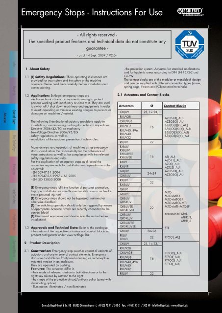
Emergency Stops - Instructions For Use
Emergency Stops - Instructions For Use
Emergency Stops - Instructions For Use
- No tags were found...

You also want an ePaper? Increase the reach of your titles
YUMPU automatically turns print PDFs into web optimized ePapers that Google loves.
<strong>Emergency</strong> <strong>Stops</strong> - <strong>Instructions</strong> <strong>For</strong> <strong>Use</strong><br />
- All rights reserved -<br />
The specified product features and technical data do not constitute any<br />
guarantee -<br />
- as of 14 Sept. 2009 / V2.0 -<br />
1 About Safety<br />
1.1 (!) Safety Regulations: These operating instructions are<br />
provided for your safety and the safety of the machine<br />
operator. Please read them carefully before installation and<br />
commissioning.<br />
1.2 Application: Schlegel emergency stops are<br />
electromechanical switch components serving to protect<br />
persons working with machinery or close to it. They are used<br />
to switch off / shut down machinery and equipments in order<br />
to avert impending or minimise existing dangers to persons or<br />
damages on machines /material.<br />
The following (inter-)national statutory provisions apply to<br />
installation, commissioning and regular technical inspections:<br />
- Directive 2006/42/EG on machinery<br />
- Low-Voltage Directive 2006/95/EG<br />
- safety regulations as well as<br />
- regulations of the accident prevention / safety rules.<br />
Manufacturers and operators of machines using emergency<br />
stops should retain the responsibility for the adherence of<br />
these instructions as well as for compliance with the relevant<br />
safety regulations and rules.<br />
<strong>For</strong> the application of emergency stops as directed the<br />
respective requirements for installation and operation must be<br />
observed:<br />
- EN 60947-5-1:2004<br />
- EN 60947-5-5:1997 + A1:2005<br />
- EN ISO 13850:2008<br />
(!) <strong>Emergency</strong> stops fulfil the function of personal protection.<br />
Improper installation or unauthorised modifications can lead to<br />
evere personal injuries!<br />
(!) <strong>Emergency</strong> stops should not be bypassed, removed or<br />
otherwise disabled!<br />
(!) The switching operation should only be triggered by means<br />
of appropriate actuators which are securely connected to the<br />
contact block!<br />
(!) Disconnect equipment and device from the mains before<br />
installation!<br />
1.3 Approvals and Technical Data: Refer to the catalogue<br />
information of the respective actuators and contact blocks or<br />
product configurator under www.schlegel.biz.<br />
2 Product Description<br />
2.1 Construction: <strong>Emergency</strong> stop switches consist of variants of<br />
actuators and one or several contact elements. <strong>Emergency</strong><br />
stops are available for front-panel mounting or as base-plate<br />
mounted version in an enclosure.<br />
They are operated by pushing.<br />
Features: The actuators differ in<br />
- their mode of release: rotation in both directions or to the<br />
right; key release by rotation to the right<br />
- the shape of the protective shroud/antilock collar (some with<br />
illuminating option)<br />
- illumination: illuminated / non-illuminated<br />
- the protection system: Actuators for standard applications<br />
and for hygienic areas according to DIN EN 1672-2 und<br />
GS-FW<br />
The contact blocks are of the modular or monoblock design<br />
and can be supplied with different connection types (screw,<br />
spring cage, Faston and PCB-mounted terminals).<br />
2.1 Actuators and Contact Blocks<br />
Actuators Ø Contact Blocks<br />
OKJUV 23,1 x 23,1<br />
RKUV28<br />
OKUVGB<br />
RKUVGB<br />
16<br />
RKUV40_496<br />
RKUV40<br />
RKUV32<br />
RRJUV 22<br />
AZOSOI(_AU)<br />
AZSOSO(_AU)<br />
BZ(L)O(5)(K)(_AU)<br />
BZ(L)OO(5)(K)(_AU)<br />
BZ(L)OI(5)(K)(_AU)<br />
BZ(L)OS(5)(K)(_AU<br />
RXBUV<br />
RXBLUV<br />
RXBLUVSE<br />
RXBUVSE 16 AT(_AU)<br />
AZ011(_AU)<br />
RXUV<br />
AZ00(_AU)<br />
RXUVP<br />
AZ(L)2(_AU)<br />
QXJUV<br />
AZOSOI(_AU)<br />
24x24<br />
QXJBUV<br />
AZSOSO(_AU<br />
RXJUV<br />
RXJBUV<br />
22<br />
QRUV<br />
MTO<br />
MTO+MTO<br />
MTO+MTOSF<br />
MTO+MTO+MTI<br />
MTO+MTI+MTOSF<br />
QRUVP<br />
QRBUV<br />
QRSKUV<br />
QRBUVSE<br />
QRSKUVSE<br />
22<br />
QRBLUV<br />
QRSKLUV<br />
QRBLUVSE<br />
QRSKLUVSE<br />
ETR<br />
QRJUV<br />
26x26<br />
FRUV<br />
FRUVL<br />
22 PTOO(_AU)<br />
OKJUV 23,1 x 23,1<br />
RKUV28<br />
OKUVGB<br />
RKUVGB<br />
16<br />
RKUV40_496<br />
RKUV40<br />
RKUV32<br />
RRJUV 22<br />
accessories: MAL,<br />
MHR_3,<br />
MHR_5<br />
PTPOO(_AU)<br />
PTPOI(_AU)<br />
PTFOO(_AU)<br />
PTFOI(_AU)<br />
Georg Schlegel GmbH & Co. KG - 88525 Dürmentingen - +49 (0) 73 71 / 502-0 - Fax: +49 (0) 73 71 / 502 49 - info@schlegel.biz - www.schlegel.biz
<strong>Emergency</strong> <strong>Stops</strong> - <strong>Instructions</strong> <strong>For</strong> <strong>Use</strong><br />
Actuators Ø ASI-Safety at Work<br />
OKJUV 23,1 x 23,1<br />
QXJBUV<br />
QXJUV<br />
RKUV28<br />
RXBUV<br />
RXBUVSE<br />
RXBLUVSE<br />
RXBLUV<br />
RKUV40_496<br />
RKUV32<br />
RXJBUV<br />
RXJUV<br />
RRJUV<br />
RXUV<br />
RXUVP<br />
QRBLUV<br />
QRBLUVSE<br />
QRBUV<br />
QRBUVSE<br />
QRSKUV<br />
QRSKUVSE<br />
QRSKLUV<br />
QRSKLUVSE<br />
QRJUV<br />
QRUV<br />
QRUVP<br />
22<br />
24x24<br />
16<br />
22<br />
16<br />
22<br />
26x26<br />
ASI_SAW16A<br />
ASI_SAW16E<br />
ASI_SAW16<br />
ASI_SAW22A<br />
ASI_SAW22E<br />
ASI_SAW22<br />
ASI_SAW16A, ASI_SAW22A, with failure switch-off and<br />
digital output for actuator lighting<br />
Base-plate mounted in an enclosure<br />
1) Mount lower enclosure section on the appropriate surface.<br />
2) Compare 3.1, steps 2 to 9.<br />
3) Insert wiring cable in the enclosure or rather connect it to<br />
the enclosure.<br />
(!) Make sure that the contact blocks used in the enclosure<br />
are connected correctly in order to comply with the<br />
clearance and creepage distance requirements for<br />
insulated enclosures on proper use.<br />
4) Close the enclosure.<br />
(!) Make sure to have the enclosure closed tightly<br />
(tighten all screws...)<br />
(!) Make sure that the emergency-stop switch is always easily<br />
accessible. This particularly applies to emergency stops with high<br />
protective shroud!<br />
3 Assembly and Commissioning<br />
3.1 Assembly <strong>Instructions</strong><br />
Front-panel mounted<br />
1) Provide the required mounting hole in the appropriate<br />
mounting plate (refer to the relative catalogue drawings).<br />
In order to ensure full tightness of the unit, make sure to<br />
have a smooth surface, particularly in case of hygienic<br />
areas and actuators with protective shroud.<br />
2) <strong>For</strong> actuators with illuminated protective shroud provide<br />
a second hole following the relative assembly drawings in<br />
the catalogue (Fig. 2).<br />
3) Insert actuator in the cutout.<br />
4) Fasten actuator with plastic nut. (observe the max.<br />
tightening torque: actuators with 16mm thread = 1.5Nm,<br />
actuators with 22mm thread = 2.5Nm)<br />
5) Snap-fit contact block to actuator neck by rotary motion<br />
(MT..., DT..., ET...) or by pressing (AT..., BT..., PTF...).<br />
Exception: The contact blocks of the type series PTP...<br />
are snapped onto the actuator and fixed by a small locking<br />
bolt through a hole in the PCB. The contact unit PTOO<br />
is put onto the neck of the actuator type FRUV(L); spacer<br />
sleeves ensure correct distance between PCB and mounting<br />
plate (Fig. 4).<br />
6) (!) Check whether contact block and actuator are<br />
snap-fitted correctly.<br />
7) Modular contact blocks (MT...) must first be correctly<br />
aligned and snapped into a module holder before<br />
snap-fitting them to the actuator. (Fig. 1)<br />
8) Connect contact block.<br />
9) <strong>For</strong> actuators with illuminated collar put the plug for lighting<br />
through the relative hole in the mounting plate<br />
and connect it to the actuator. (Fig. 2 and 3)<br />
Fig. 1: correct assembly of modular contact blocks<br />
Fig. 2: mounting hole for illuminated E-stop<br />
Georg Schlegel GmbH & Co. KG - 88525 Dürmentingen - +49 (0) 73 71 / 502-0 - Fax: +49 (0) 73 71 / 502 49 - info@schlegel.biz - www.schlegel.biz
<strong>Emergency</strong> <strong>Stops</strong> - <strong>Instructions</strong> <strong>For</strong> <strong>Use</strong><br />
1.80<br />
7.8<br />
10.8<br />
13.0<br />
1.30<br />
1.50<br />
35<br />
mounting plate<br />
1 ... 3<br />
spacer sleeve<br />
9±0,1<br />
PCB<br />
captive nut<br />
Fig. 3: assembly sequence Fig. 4: FRUV(L) with PTOO<br />
4 Testing Before Initial Operation:<br />
Mechanical Test: <strong>Emergency</strong> stop latches when operated<br />
Electrical Test: Machine stops / switches off on actuation of the<br />
E-stop.<br />
5 Maintenance and Repair:<br />
It is recommended to have the E-stop triggered for testing<br />
purposes at least once a year by the responsible safety officer<br />
in order to ensure its proper function.<br />
6 More <strong>Use</strong>ful Particulars :<br />
<strong>For</strong> cleaning the emergency stops in hygienic areas (QRUVP,<br />
RXUVP) use proper detergents!<br />
Note:<br />
- good resistance to acids, lyes and alcohols<br />
- no/limited resistance to hydrocarbons (benzine, oil, etc.)!<br />
- high resistance to ozone and UV<br />
Georg Schlegel GmbH & Co. KG - 88525 Dürmentingen - +49 (0) 73 71 / 502-0 - Fax: +49 (0) 73 71 / 502 49 - info@schlegel.biz - www.schlegel.biz
<strong>Emergency</strong> <strong>Stops</strong> - <strong>Instructions</strong> <strong>For</strong> <strong>Use</strong><br />
7 EC Declaration of Conformity:<br />
Name/address of issuer:<br />
Responsible for documentation:<br />
Product description<br />
Type references:<br />
Georg Schlegel GmbH & Co. KG, Kapellenweg 4, 88525 Dürmentingen<br />
T.Gairing, Georg Schlegel GmbH & Co. KG,<br />
Kapellenweg 4, 88525 Dürmentingen<br />
<strong>Emergency</strong>-stop switches<br />
see table 2.1 above<br />
The referenced products comply with the provisions of the following directives:<br />
Directive: dd.: applicable norms: referred to:<br />
2006/95/EG 12.12.2006 EN 60947-5-1:2004, contact blocks, actuators<br />
EN 60947-5-5:1997+A1:2005<br />
2006/42/EG *) 17.05.2006 EN 60947-5-5:1997+A1:2005, contact blocks, actuators, ASI-Safety<br />
EN ISO 13850:2008<br />
2004/108/EG 12.12.2006 EN 50295:1998 ASI-Safety<br />
*) applicable as of 29 Dec.2009<br />
Dürmentingen, 14 Sept. 2009<br />
Georg Schlegel GmbH & Co. KG - 88525 Dürmentingen - +49 (0) 73 71 / 502-0 - Fax: +49 (0) 73 71 / 502 49 - info@schlegel.biz - www.schlegel.biz