USB/PCI Precision Timer Relay Board (PTRB-C) Specifications & Installation Guide
PTRB User's Manual.pdf - LaserLinc, Inc.
PTRB User's Manual.pdf - LaserLinc, Inc.

Create successful ePaper yourself
Turn your PDF publications into a flip-book with our unique Google optimized e-Paper software.
<strong>USB</strong>/<strong>PCI</strong> <strong>Precision</strong> <strong>Timer</strong> <strong>Relay</strong> <strong>Board</strong><br />
(<strong>PTRB</strong>-C)<br />
<strong>Specifications</strong> & <strong>Installation</strong> <strong>Guide</strong><br />
Nov 2011<br />
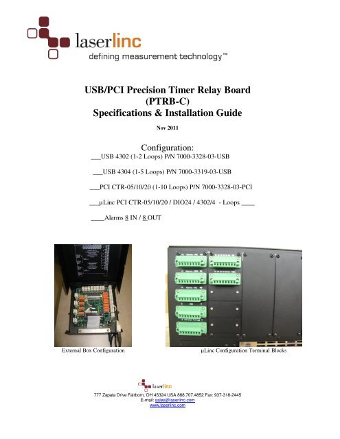
Configuration:<br />
___<strong>USB</strong> 4302 (1-2 Loops) P/N 7000-3328-03-<strong>USB</strong><br />
___<strong>USB</strong> 4304 (1-5 Loops) P/N 7000-3319-03-<strong>USB</strong><br />
___<strong>PCI</strong> CTR-05/10/20 (1-10 Loops) P/N 7000-3328-03-<strong>PCI</strong><br />
___µLinc <strong>PCI</strong> CTR-05/10/20 / DIO24 / 4302/4 - Loops ____<br />
____Alarms 8 IN / 8 OUT<br />
External Box Configuration<br />
µLinc Configuration Terminal Blocks<br />
777 Zapata Drive Fairborn, OH 45324 USA 888.707.4852 Fax: 937-318-2445<br />
E-mail: sales@laserlinc.com<br />
www.laserlinc.com
Copyright Notice<br />
© LaserLinc, Inc. 1999-2011<br />
All rights reserved<br />
Trademarks<br />
TLAser, TLAser400, LaserLinc and Total Vu are trademarks of LaserLinc, Inc.<br />
All other product names are trademarks of their respective owners.<br />
Copyright<br />
LaserLinc, Inc. copyrights this manual with all rights reserved. Under the copyright laws, this manual may not be reproduced in<br />
any form, in whole or part, without prior written consent of LaserLinc, Inc.<br />
Disclaimer<br />
LaserLinc, Inc. has reviewed this manual thoroughly in order that it will be an easy to use guide to your <strong>Precision</strong> <strong>Timer</strong> <strong>Relay</strong><br />
Box . All statements, technical information, and recommendations in this manual and in any guides or related documents are<br />
believed reliable, but the accuracy and completeness thereof are not guaranteed or warranted, and they are not intended to be,<br />
nor should they be understood to be, representations or warranties concerning the product described.<br />
Your laser scan micrometer hardware and software included with your system have been sold to you subject to the limited<br />
warranties set forth in the warranty section set forth in your quote you were issued before purchase and license agreement<br />
enclosed with the software CD. Further, LaserLinc, Inc. reserves the right to make changes in the specifications of the products<br />
described in this manual at any time without notice and without obligation to notify any person of such change.<br />
If you have questions regarding your laser scan micrometer system or the information in this manual, please<br />
call LaserLinc, Inc. customer service department at 1-888-707-4852.<br />
Trademarks<br />
LaserLinc, TLAser122, TLAser222, TLAser122s, Triton312, Triton 330, Triton360, TLAser400 and Total Vu<br />
are registered trademarks. The LaserLinc logo is a trademark of LaserLinc, Inc.<br />
Other brands and product names mentioned in this manual may be trademarks or registered trademarks of their respective<br />
companies.<br />
LaserLinc, Inc.<br />
777 Zapata Dr ▪ Fairborn OH 45324<br />
Phone: 937-318-2440 ▪ Fax: 937-318-2445<br />
info@laserlinc.com ▪ www.laserlinc.com<br />
777 Zapata Drive Fairborn, OH 45324 USA 888.707.4852 Fax: 937-318-2445<br />
E-mail: sales@laserlinc.com<br />
www.laserlinc.com
ERRATA: May 25 th , 2010<br />
1) Control Loop Timing for <strong>USB</strong> based <strong>PTRB</strong> products<br />
NOTE: See Page 7, Item 5 – CLOCK SPEED; change to 1 MHz.<br />
2) MOP AUTO/MANUAL Switch<br />
If using MOP 3 & MOP 4 configurations, The AUTO/MANUAL switch inputs must be defined on DIN<br />
4 & DIN 5 respectively within TotalVu’s “Digital Inputs” configuration.<br />
(MOP 1 & MOP 2 AUTO/MANUAL switches are predefined on DIN 6 & DIN 7 respectively).<br />
3) <strong>USB</strong> Power Management – Disable<br />
In Device Manager select ‘<strong>USB</strong> Root Hub’, & uncheck ‘Allow Computer to turn off this device to save<br />
power’ See Page 8 – Disable <strong>USB</strong> Power Management<br />
777 Zapata Drive Fairborn, OH 45324 USA 888.707.4852 Fax: 937-318-2445<br />
E-mail: sales@laserlinc.com<br />
www.laserlinc.com
777 Zapata Drive Fairborn, OH 45324 USA 888.707.4852 Fax: 937-318-2445<br />
E-mail: sales@laserlinc.com<br />
www.laserlinc.com
Read Me First: Safety and<br />
Electromagnetic Compatibility<br />
This document contains safety instructions and electromagnetic compatibility (EMC) information for the<br />
hardware it accompanies. This document is a supplement to the hardware documentation. Read this page<br />
before installing and using the hardware.<br />
Safety Information<br />
This section contains important safety information that you must follow when installing and using the<br />
hardware.<br />
Do not operate the hardware in a manner not specified in this document and in the user documentation. Misuse<br />
of the hardware can result in a hazard. You can compromise the safety protection if the hardware is damaged<br />
in any way. If the hardware is damaged, return it to LaserLinc for repair<br />
.<br />
Do not substitute parts or modify the hardware except as described in this document. Use the hardware only<br />
with the accessories and cables specified in the installation instructions or specifications. You must have all<br />
covers installed during operation of the hardware.<br />
Do not operate the hardware in an explosive atmosphere or where there may be flammable gases or fumes.<br />
Prior to connecting or disconnecting external devices from the hardware, always first disconnect the power<br />
cord from the <strong>Precision</strong> <strong>Timer</strong> <strong>Relay</strong> Box.<br />
777 Zapata Drive Fairborn, OH 45324 USA 888.707.4852 Fax: 937-318-2445<br />
E-mail: sales@laserlinc.com<br />
www.laserlinc.com<br />
1
Preface<br />
This manual is intended for any user, or potential user, of the LaserLinc <strong>Precision</strong> <strong>Timer</strong> <strong>Relay</strong> Box. It is a<br />
supplement to the LaserLinc Total Vu software manual. The goal of this manual is to cover only items<br />
and features specific to the <strong>Precision</strong> <strong>Timer</strong> <strong>Relay</strong> Box. For general features and operation, refer to the<br />
Total Vu software manual.<br />
Included is a Quick Start <strong>Guide</strong> for the <strong>Precision</strong> <strong>Timer</strong> <strong>Relay</strong> Box. This may allow you to get your<br />
<strong>Precision</strong> <strong>Timer</strong> <strong>Relay</strong> Box up and running quickly, especially if you are an experienced <strong>Precision</strong> <strong>Timer</strong><br />
<strong>Relay</strong> Box user. It may also be used to answer some questions quickly. But the Quick Start <strong>Guide</strong> is not<br />
intended to replace the full manual and will not address every application.<br />
Software development is always ongoing at LaserLinc. You may encounter a feature in your version of<br />
Total Vu software that appears to differ from the description in this manual. If you encounter such a<br />
feature and have a question about it or an issue with it, please contact LaserLinc directly for an answer or<br />
clarification. Contact information is available at the beginning of this document, or at<br />
http://www.LaserLinc.com.<br />
777 Zapata Drive Fairborn, OH 45324 USA 888.707.4852 Fax: 937-318-2445<br />
E-mail: sales@laserlinc.com<br />
www.laserlinc.com<br />
2
Compliance<br />
Electromagnetic Compatibility Information<br />
This hardware has been tested and found to comply with the applicable regulatory requirements and limits<br />
for electromagnetic compatibility (EMC) as indicated in the hardware’s Declaration of Conformity (DoC).<br />
These requirements and limits are designed to provide reasonable protection against harmful interference<br />
when the hardware is operated in the intended electromagnetic environment. In special cases, for example<br />
when either highly sensitive or noisy hardware is being used in proximity, additional mitigation measures<br />
may have to be employed to minimize the potential for electromagnetic interference<br />
While this hardware is compliant with the applicable regulatory EMC requirements, there is no guarantee<br />
that interference will not occur in a particular installation. To minimize the potential for the hardware to<br />
cause interference to radio and television reception or to experience unacceptable performance<br />
degradation, install and use this hardware in strict accordance with the instructions in the hardware<br />
documentation and the DoC.<br />
If this hardware does cause interference with licensed radio communications services or other nearby<br />
electronics, which can be determined by turning the hardware off and on, you are encouraged to try to<br />
correct the interference by one or more of the following measures:<br />
• Reorient the antenna of the receiver (the device suffering interference).<br />
• Relocate the transmitter (the device generating interference) with respect to the receiver.<br />
• Plug the transmitter into a different outlet so that the transmitter and the receiver are on different branch<br />
circuits.<br />
Operation of this hardware in a residential area is likely to cause harmful interference. Users are required<br />
to correct the interference at their own expense or cease operation of the hardware. Changes or<br />
modifications not expressly approved by LaserLinc could void the user’s right to operate the hardware<br />
under the local regulatory rules.<br />
The Declaration of Conformity (DoC) contains important EMC compliance information and instructions for the user or installer.<br />
777 Zapata Drive Fairborn, OH 45324 USA 888.707.4852 Fax: 937-318-2445<br />
E-mail: sales@laserlinc.com<br />
www.laserlinc.com<br />
3
FCC/DOC Radio Frequency Interference Class A Compliance<br />
This equipment generates and uses radio frequency energy and, if not installed and used in strict<br />
accordance with the instructions in this manual, may cause interference to radio and television reception.<br />
Classification requirements are the same for the Federal Communications Commission (FCC) and the<br />
Canadian Department of Communications (DOC). This equipment has been tested and found to comply<br />
with the following two regulatory agencies:<br />
Federal Communications Commission<br />
This equipment has been tested and found to comply with the limits for a Class A digital device, pursuant<br />
to part 15 of the FCC Rules. These limits are designed to provide reasonable protection against harmful<br />
interference when the equipment is operated in a commercial environment. This equipment generates,<br />
uses, and can radiate radio frequency energy and, if not installed and used in accordance with the<br />
instruction manual, may cause harmful interference to radio communications. Operation of this equipment<br />
in a residential area is likely to cause harmful interference in which case the user will be required to<br />
correct the interference at user’s expense.<br />
Notices to User<br />
Changes or modifications not expressly approved by LaserLinc could void the user’s authority to<br />
operate the equipment under the FCC Rules.<br />
This device complies with the FCC rules only if used with shielded interface cables of suitable<br />
quality and construction. LaserLinc used such cables to test this device and provides them for sale to<br />
the user. The use of inferior or non-shielded interface cables could void the user’s authority to<br />
operate the equipment under the FCC rules.<br />
If necessary, consult LaserLinc or an experienced radio/television technician for additional suggestions.<br />
The following booklet prepared by the FCC may also be helpful: Interference to Home Electronic<br />
Entertainment Equipment Handbook. This booklet is available from the U.S. Government Printing Office,<br />
Washington, DC 20402.<br />
Canadian Department of Communications<br />
This Class-A digital apparatus complies with Canadian ICES-001<br />
Cet appareil numérique de la classe-A est conforme à la norme NMB-001 du Canada<br />
777 Zapata Drive Fairborn, OH 45324 USA 888.707.4852 Fax: 937-318-2445<br />
E-mail: sales@laserlinc.com<br />
www.laserlinc.com<br />
4
Conventions<br />
– This icon denotes a caution, which advises you of precautionary measures to avoid injury, data<br />
loss, or a system crash. When this symbol is marked on the product, refer to the Read Me First: Safety and<br />
Electromagnetic Compatibility section of this manual for precautions to take.<br />
This icon denoted a caution, risk of electrical shock, which advises you of precautionary measures<br />
to avoid injury. When this symbol is marked on the product, refer to the Read Me First: Safety and<br />
Electromagnetic Compatibility section of this manual for precautions to take.<br />
Intended Use of the Equipment<br />
The <strong>Precision</strong> <strong>Timer</strong> <strong>Relay</strong> Box (<strong>PTRB</strong>) is an input / output device used in conjunction with LaserLinc’s<br />
micrometers and ultrasonic measurement systems and provides dry contact switches to perform alarming,<br />
input indictors and closed loop control. Common connections would include AC or DC lights, audible<br />
alarms, switch closures from other devices such as Programmable Logic Controllers (PLC) or extruders.<br />
<strong>Installation</strong> and Configuration<br />
<strong>PTRB</strong> — Safety Considerations<br />
The <strong>PTRB</strong> must be placed in a location where it is easy for the operator to disconnect the power cord from<br />
either the <strong>PTRB</strong> or from where it is plugged into in case of an emergency.<br />
This equipment may contain voltage hazardous to human life and safety, and is capable of inflicting<br />
personal injury. To completely remove all power, ALL users’ wires entering the <strong>PTRB</strong> must be removed.<br />
This is easily accomplished using the pluggable terminals contained within.<br />
– Caution: Before undertaking any maintenance procedure, carefully read the following caution<br />
notices<br />
• Explosive Atmosphere—Do not operate the box in conditions where flammable gases are<br />
present. Under such conditions, this equipment is unsafe and may ignite the gases or gas fumes.<br />
777 Zapata Drive Fairborn, OH 45324 USA 888.707.4852 Fax: 937-318-2445<br />
E-mail: sales@laserlinc.com<br />
www.laserlinc.com<br />
5
• Part Replacement—Only service this equipment with parts that are exact replacements, both<br />
electrically and mechanically. Contact LaserLinc for replacement part information. <strong>Installation</strong><br />
of parts with those that are not direct replacements may cause harm to personnel operating the<br />
<strong>PTRB</strong>. Furthermore, damage or fire may occur if replacement parts are unsuitable.<br />
• Modification — Do not modify any part of the <strong>PTRB</strong> from its original condition. Unsuitable<br />
modifications may result in safety hazards.<br />
777 Zapata Drive Fairborn, OH 45324 USA 888.707.4852 Fax: 937-318-2445<br />
E-mail: sales@laserlinc.com<br />
www.laserlinc.com<br />
6
Table of Contents<br />
1 SPECIFICATIONS.........................................................................................................................................................9<br />
1.1 TIMER RELAY - CONTROL LOOP OUTPUT SPECIFICATIONS:........................................................................................9<br />
1.2 ALARMS - DIGITAL OUTPUT SPECIFICATIONS ...............................................................................................................9<br />
1.3 DIGITAL ISOLATED INPUTS ..........................................................................................................................................10<br />
1.4 PHYSICAL / ELECTRICAL.............................................................................................................................................10<br />
2 PRECISION TIMER / DIGITAL I/O SPECIFICATION / INSTALLATION ...........................................................11<br />
2.1 DESCRIPTION ..............................................................................................................................................................11<br />
2.2 CONFIGURATION .........................................................................................................................................................11<br />
2.3 INSTALLATION PROCEDURE <strong>USB</strong> – ADD ON ................................................................................................................14<br />
2.4 INSTALLATION PROCEDURE <strong>PCI</strong> – ADD ON .................................................................................................................17<br />
3 WIRING PROCEDURE...............................................................................................................................................19<br />
3.1 DIGITAL INPUT............................................................................................................................................................19<br />
3.1.1 USING AN EXTERNAL VOLTAGE SOURCE ....................................................................................................................19<br />
3.1.2 USING AN INTERNAL VOLTAGE SOURCE (<strong>PTRB</strong> ONLY) ...............................................................................................24<br />
3.2 MOP CONNECTIONS ...................................................................................................................................................26<br />
3.3 COUNTER (ENCODER) INPUTS .....................................................................................................................................27<br />
4 TESTING PROCEDURE .............................................................................................................................................28<br />
4.1 TESTING ALARMS........................................................................................................................................................28<br />
4.2 TESTING DIGITAL INPUTS............................................................................................................................................28<br />
4.3 TESTING CLOSED LOOP CONTROL (RELAYS)..............................................................................................................29<br />
4.4 TESTING CLOSED LOOP CONTROL (MOP)..................................................................................................................29<br />
5 EXAMPLE CONFIGURATIONS................................................................................................................................31<br />
5.1 DIGITAL INPUTS ..........................................................................................................................................................31<br />
5.1.1 RESET FOOTAGE COUNTER EXAMPLE .........................................................................................................................33<br />
5.1.2 USING DIGITAL INPUT TO TRIGGER AN ACTION...........................................................................................................34<br />
5.1.3 USING DIGITAL INPUT TO TRIGGER AN ALARM ...........................................................................................................35<br />
5.1.4 USING DIGITAL INPUT TO TRIGGER A RELAY (DIGITAL OUTPUT) .................................................................................36<br />
5.1.5 RECORD DIGITAL INPUT IN PROCESS TRACKER ...........................................................................................................37<br />
5.1.6 RECORD DIGITAL INPUT AS FLAW DETECTION EVENT .................................................................................................38<br />
5.1.7 RECORD DIGITAL INPUT IN DATA LOG FILE.................................................................................................................39<br />
5.1.8 SWITCH BETWEEN DIGITAL INPUT ASSOCIATED ACTIONS USING A BUTTON .................................................................40<br />
777 Zapata Drive Fairborn, OH 45324 USA 888.707.4852 Fax: 937-318-2445<br />
E-mail: sales@laserlinc.com<br />
www.laserlinc.com<br />
7
777 Zapata Drive Fairborn, OH 45324 USA 888.707.4852 Fax: 937-318-2445<br />
E-mail: sales@laserlinc.com<br />
www.laserlinc.com<br />
8
1 <strong>Specifications</strong><br />
Typical for 25°C unless otherwise specified.<br />
1.1 <strong>Timer</strong> <strong>Relay</strong> - Control Loop Output <strong>Specifications</strong>:<br />
• Number of loops:<br />
<strong>PCI</strong> CTR-05 – two / <strong>PCI</strong> CTR-10 – five / <strong>PCI</strong> CTR-20 - ten<br />
<strong>USB</strong> 4302 – two / <strong>USB</strong> 4304 - five<br />
• Contact configuration FORM C (SPDT) NO, NC and Common available at connector<br />
• Contact rating 5 amperes (A) @ 250 volts AC (VAC) or 28 volts DC (VDC) resistive<br />
• Will support up to (4) LaserLinc Motorized Potentiometers (MOP)<br />
• Contact resistance 100 milliohms max<br />
• Operate time 5 milliseconds (ms) max<br />
• Release time 2 ms max<br />
• Bounce time: 1ms typ. At nom. voltage<br />
• Vibration: 10 to 55 hertz (Hz) (Dual amplitude 1.5 millimeters (mm)<br />
• Shock: 10 G (11 ms)<br />
• Dielectric isolation: 500 V (1 minute)<br />
• Life expectancy: 15 million mechanical operations, min<br />
• Switch Rate: 360-ops/hr. max at rated load<br />
• Power on RESET state: Not energized. NC in contact to Common<br />
1.2 Alarms - Digital Output specifications<br />
• Number of outputs:<br />
<strong>PCI</strong> CTR-05 – eight / <strong>PCI</strong> CTR-10 – eight / <strong>PCI</strong> CTR-20 – none<br />
<strong>USB</strong> 4302 – eight / <strong>USB</strong> 4304 – eight<br />
• Contact configuration 10 FORM C (SPDT) NO, NC and Common available at connector<br />
• Contact rating 5 amperes (A) @ 250 volts AC (VAC) or 28 volts DC (VDC) resistive<br />
777 Zapata Drive Fairborn, OH 45324 USA 888.707.4852 Fax: 937-318-2445<br />
E-mail: sales@laserlinc.com<br />
www.laserlinc.com<br />
9
• Contact resistance 100 milliohms (m.) max<br />
• Operate time 5 milliseconds (ms) max<br />
• Release time 2 ms max<br />
• Bounce time: 1ms typ. At nom. voltage<br />
• Vibration: 10 to 55 hertz (Hz) (Dual amplitude 1.5 millimeters (mm))<br />
• Shock: 10 G (11 ms)<br />
• Dielectric isolation: 500 V (1 minute)<br />
• Life expectancy: 15 million mechanical operations, min<br />
• Switch Rate: 360-ops/hr. max at rated load<br />
• Power on RESET state: Not energized. NC in contact to Common<br />
1.3 Digital isolated inputs<br />
• Polarity: Non Polarized, (+/-) 2-30 VDC<br />
• Number of inputs:<br />
<strong>PCI</strong> CTR-05 – eight / <strong>PCI</strong> CTR-10 – eight / <strong>PCI</strong> CTR-20 – none<br />
<strong>USB</strong> 4302 – eight / <strong>USB</strong> 4304 – eight<br />
• Isolation 500 volts (V)<br />
• Resistance 1.6K ohms<br />
• Input range +/- (2–30) VDC max<br />
1.4 Physical / Electrical<br />
• 10”L (254mm) x 8”W (203mm) (w/o MOP connectors)<br />
• 14”L (356mm) x 8”W(203mm) (w/ MOP connectors)<br />
• Weight: 4lb (1.8kg)<br />
• Power<br />
<strong>PCI</strong> version: powered from CTR-05/10/20<br />
<strong>USB</strong> : AC wall adapter, Universal power, 100-240 VAC, 50-60 Hz,<br />
5VDC @ 0.5A<br />
• Ambient Temp. 45F–110F, relative humidity 10%-90% non-condensing<br />
777 Zapata Drive Fairborn, OH 45324 USA 888.707.4852 Fax: 937-318-2445<br />
E-mail: sales@laserlinc.com<br />
www.laserlinc.com<br />
10
2 <strong>Precision</strong> <strong>Timer</strong> / Digital I/O Specification / <strong>Installation</strong><br />
2.1 Description<br />
The <strong>Precision</strong> <strong>Timer</strong> <strong>Relay</strong> <strong>Board</strong> (<strong>PTRB</strong>) integrates the functions of closed loop control and digital I/O<br />
(alarming and user inputs) into one compact package for use with Total Vu software.<br />
External alarms and user-supplied input switches allow users a method of connecting external devices<br />
such as audible or visual alarms, cutters, sprayers, footswitch inputs etc.<br />
For closed loop control, precision timed, pluggable, FORM C, 5 AMP relay contact closures are provided<br />
for “Jog-up” and “Jog-down” functions. Optionally, LaserLinc’s MOPs may also be connected (MOPs not<br />
included). See Section 3.4 below for MOP testing and installation. For alarming, pluggable, FORM C, 5<br />
AMP relay contact closures are provided. For user inputs, (+/-) 2-30 VDC, non-polarized, pluggable,<br />
terminal contacts are provided.<br />
2.2 Configuration<br />
The <strong>PTRB</strong> is supplied in three different configurations. LaserLinc will automatically supply the<br />
appropriate configuration based upon your hardware requirements.<br />
Option 1: (1-2 Control Loops), 4302 / <strong>PCI</strong> CTR-05 Version:<br />
Digital I/O - 8 inputs, 8 alarm outputs<br />
Control - 2 Loops Digital Pulse Width or 1 Loop Pulse Count<br />
Option 2: (1-5 Control Loops), 4304 / <strong>PCI</strong> CTR-10 Version:<br />
Digital I/O - 8 inputs, 8 alarm outputs<br />
Control - 5 Loops Digital Pulse Width, or<br />
- 2 Loops Pulse Count & 1 Loop Digital Pulse Width, or<br />
- 1 Loop Pulse Count & 3 Loops Digital Pulse Width<br />
777 Zapata Drive Fairborn, OH 45324 USA 888.707.4852 Fax: 937-318-2445<br />
E-mail: sales@laserlinc.com<br />
www.laserlinc.com<br />
11
Option 3: (1 –10 control loops), (<strong>PCI</strong> CTR-20, Integral alarming and input functions are not available in<br />
this package. An additional <strong>USB</strong> based I/O device is available).<br />
Digital I/O - Not Available<br />
Control - 10 Loops Digital Pulse Width, or<br />
- 1 Loop Pulse Count & 8 Loops Digital Pulse Width, or<br />
- 2 Loops Pulse Count & 6 Loops Digital Pulse Width, or<br />
- 3 Loops Pulse Count & 4 Loops Digital Pulse Width, or<br />
- 4 Loops Pulse Count & 2 Loops Digital Pulse Width<br />
Configuration – Total Vu Hardware Mapping<br />
777 Zapata Drive Fairborn, OH 45324 USA 888.707.4852 Fax: 937-318-2445<br />
E-mail: sales@laserlinc.com<br />
www.laserlinc.com<br />
12
(8) Input<br />
Terminals<br />
(+/-) 2-30<br />
VDC<br />
(4) Control Jog<br />
<strong>Relay</strong>s SPDT<br />
Option 1 - Hardware Configuration Shown<br />
<strong>PCI</strong> CTR-05<br />
(8) Output<br />
<strong>Relay</strong>s FORM C<br />
5A @ 250 VAC<br />
SPDT<br />
Interface Cable to<br />
PC’s - CTR-05<br />
/10 card<br />
Strain Relief<br />
Tie-down bar<br />
AC Power adapter<br />
Twist lock<br />
Interface Cable to<br />
PC’s <strong>USB</strong> Port<br />
Option 2 - Hardware Configuration Shown<br />
<strong>USB</strong> 4304<br />
w/AC Power Adapter<br />
777 Zapata Drive Fairborn, OH 45324 USA 888.707.4852 Fax: 937-318-2445<br />
E-mail: sales@laserlinc.com<br />
www.laserlinc.com<br />
13
2.3 <strong>Installation</strong> Procedure <strong>USB</strong> – add on<br />
This section assumes that the <strong>PCI</strong> TLAser400 Interface Card and Total Vu software are installed, a<br />
scanner is connected and calibrated, and a measurement is defined. Refer to the Total Vu Operator’s<br />
Manual for further details. If you have a <strong>PTRB</strong> <strong>PCI</strong> version, skip ahead to section 2.4<br />
1) Install the InstaCal Software by browsing to the InstaCal folder in “C:\Program<br />
Files\LaserLinc\Total Vu” or the Total Vu CD “\InstalCal” and executing “icalsetup5.85.exe”.<br />
2) Connect the <strong>USB</strong> cable from the <strong>PTRB</strong> to any PC <strong>USB</strong> connection. Connect AC power adapter to<br />
front panel. Ensure the ‘twist-lock’ connector engages.<br />
3) Windows will detect a new Plug-N-Play device. Wait until the message says “Ready to Use”.<br />
4) Execute the InstaCal software. INSURE THE <strong>USB</strong> 4302/4,CTR-05/10/20 CARD IS DETECTED<br />
BY INSTACAL.<br />
5) IMPORTANT - For <strong>USB</strong>-4302/4 ONLY: Double click on the entry <strong>USB</strong>-4302/4<br />
Select “Clock Speed” pull-down menu, and change to 1 MHz, click “OK”.<br />
Select 1 MHz Clock Speed<br />
777 Zapata Drive Fairborn, OH 45324 USA 888.707.4852 Fax: 937-318-2445<br />
E-mail: sales@laserlinc.com<br />
www.laserlinc.com<br />
14
6) Exit InstaCal.<br />
7) Disable <strong>USB</strong> Power Management<br />
Enter Windows Device Manager - Select START\CONTROL PANEL\SYSTEM, Select HARDWARE<br />
tab, select Device Manager, select Universal Serial Bus Controller<br />
Select <strong>USB</strong> Root Hub, Power Management tab – uncheck “Allow the computer to turn off this device<br />
to save power” (If there are more than one <strong>USB</strong> ROOT HUBS ,repeat for each occurrence )<br />
777 Zapata Drive Fairborn, OH 45324 USA 888.707.4852 Fax: 937-318-2445<br />
E-mail: sales@laserlinc.com<br />
www.laserlinc.com<br />
15
8) If the CONTROL and/or DIO option was purchased as an “add-on”, after, the original Total Vu<br />
installation, copy the file TotalVu.bin from the CD or <strong>USB</strong> flash drive to your Total Vu folder (default<br />
is c:\program files\LaserLinc\Total Vu). This file enables the CONTROL and/or DIO option in your<br />
software.<br />
9) Execute Total Vu.<br />
10) Select the Configure/Full Configuration screen and verify the appropriate icon; “4302/4-1”, icon now<br />
appears.<br />
11) Double Click on the 4302-1 icon<br />
- highlight Wiring Label Style<br />
- Select Change Setting button<br />
- Select <strong>Precision</strong> <strong>Timer</strong> <strong>Relay</strong> <strong>Board</strong> and hit OK to close<br />
The <strong>PTRB</strong> should now be working.<br />
777 Zapata Drive Fairborn, OH 45324 USA 888.707.4852 Fax: 937-318-2445<br />
E-mail: sales@laserlinc.com<br />
www.laserlinc.com<br />
16
2.4 <strong>Installation</strong> Procedure <strong>PCI</strong> – add on<br />
This section assumes that the <strong>PCI</strong> TLAser400 Interface Card and Total Vu software are installed, a<br />
scanner is connected and calibrated, and a measurement is defined. Refer to the Total Vu Operator’s<br />
Manual for further details. If you have a <strong>PTRB</strong> <strong>USB</strong> version, go back to section 2.3<br />
1) Power down the PC.<br />
2) Install the <strong>PCI</strong> CTR-05/10/20 into any available <strong>PCI</strong> slot in the PC.<br />
3) Connect the cable from the <strong>PTRB</strong> to the PC backpanel <strong>PCI</strong> CTR-05/10/20 connector.<br />
4) Restart computer and boot Windows.<br />
5) Windows will detect a new Plug-N-Play device, place the Total Vu CD into the CD drive and let<br />
Windows automatically find the driver. Follow the Window’s prompts until finished.<br />
6) Install the InstaCal Software by browsing to the Total Vu CD \InstalCal folder and executing<br />
“SETUP.EXE”.<br />
7) After rebooting, execute the InstaCal software; INSURE THE <strong>PCI</strong> CTR-05/10/20 CARD IS<br />
DETECTED BY INSTACAL, then exit.<br />
8) If the CONTROL and/or DIO option was purchased as an “add-on”, after, the original Total Vu<br />
installation, copy the file TotalVu.bin from the CD or <strong>USB</strong> flash drive to your Total Vu folder<br />
(default is c:\program files\LaserLinc\Total Vu). This file enables the CONTROL and/or DIO<br />
option in your software.<br />
9) Execute Total Vu.<br />
10) Select the Configure/Full Configuration screen and verify the appropriate icon; CTR-05/10/20<br />
icon now appears.<br />
777 Zapata Drive Fairborn, OH 45324 USA 888.707.4852 Fax: 937-318-2445<br />
E-mail: sales@laserlinc.com<br />
www.laserlinc.com<br />
17
11) Double Click on the CTR-05/10/20-1 icon<br />
- highlight Wiring Label Style<br />
- Select Change Setting button<br />
- Select <strong>Precision</strong> <strong>Timer</strong> <strong>Relay</strong> <strong>Board</strong> and hit OK to close<br />
The <strong>PTRB</strong> should now be working.<br />
777 Zapata Drive Fairborn, OH 45324 USA 888.707.4852 Fax: 937-318-2445<br />
E-mail: sales@laserlinc.com<br />
www.laserlinc.com<br />
18
3 Wiring Procedure<br />
3.1 Digital Input<br />
Both the <strong>PTRB</strong> and the PDIS08 have (8) digital input terminals. In order for these devices to receive a<br />
digital input the voltage difference between the two contacts on one of the terminals needs to change by a<br />
specified amount. There are two methods of producing this change in voltage difference for the <strong>PTRB</strong> as<br />
described below (3.1.1 and 3.1.2). The PDIS08 is only able to use the option described under 3.1.1.<br />
3.1.1 Using an External Voltage Source<br />
In order to transmit a digital signal a complete electrical circuit must be formed. That is why we provide<br />
two contacts on each digital input terminal. Two separate wires are needed to make an electrical<br />
connection between these two contacts on the terminal and the voltage source provided by the customer.<br />
The two leads on a voltmeter can be used to measure the voltage difference between these two wires. For<br />
digital applications the voltage difference between these two wires can either be equal (Voltage = 0 V) or<br />
different (Voltage = 2-30 V). It is the change between these two states that transmits the digital signal.<br />
Within this simple change in voltage are three variables that can be potentially reversed. In foresight our<br />
product developers made each variable reversible. You may connect the wires to the terminal in any order<br />
you prefer (polarity does not matter). You can also set the ON signal to trigger on either the change to<br />
equal voltage (0 V)(negative logic) or on the change to a difference in voltage (2-30 V)(positive logic).<br />
Lastly you can configure only an ON action (Momentary) or an ON and an OFF action (Maintained). At<br />
this point all you need to know is that just as long as you involve only one terminal you can connect these<br />
two wires in any order you desire.<br />
The following describes how to connect the two wires to the digital input terminal. First select one of your<br />
eight inputs (DIN0 – DIN7) (<strong>PTRB</strong>) or (IP0 – IP7) (PDIS08). Take a screwdriver and turn the screw<br />
shown in the following picture counterclockwise until opening below for the wire is all the way open.<br />
Strip the last 0.25 inch of insulation off the wire and insert the bare portion into this opening. Then turn<br />
the screw clockwise until the opening is closed and snug. Give each wire a small tug to ensure they are not<br />
going to slip out.<br />
777 Zapata Drive Fairborn, OH 45324 USA 888.707.4852 Fax: 937-318-2445<br />
E-mail: sales@laserlinc.com<br />
www.laserlinc.com<br />
19
With your wires connected to your <strong>PTRB</strong> or PDIS08 you now have two methods of providing a switched<br />
voltage source on the other end of your wires. The method you choose is dependent on the device you<br />
plan to receive the digital signal from.<br />
The first method is if your signal source has its own internal power supply you will connect your two<br />
wires directly to the signal output of the device. If the signal source is only supplying one signal wire<br />
connection, the return wire may need to connect to the device’s ground. Ensure that the source signal is<br />
+/- 2-30 V DC using documentation and/or a voltmeter.<br />
The second more common method is used when all that is provided as a source signal is a dry contact<br />
switch closure. This method will work with both the <strong>PTRB</strong> and the PDIS08. This method consists of<br />
wiring the dry contact switch and a voltage source in series between your two wires. If you don’t have a<br />
voltage source find a DC power supply from any household electronic. It is identified with a distinctive<br />
box shape either midway (for laptops) or at the plug end. Look on the box and verify it indicates a voltage<br />
between 2 and 30 V DC (just about any power rating (W) will suffice). Cut the end off and you will have<br />
your two wires with voltage source included. The PDIS08 also has a power out plug identical to the power<br />
in plug for the device power supply. This power out plug may be used for your voltage source as shown<br />
below in Figure 3-3 and Figure 3-4. If you are using a dry contact switch with a <strong>PTRB</strong> and do not have a<br />
voltage source see section 3.1.2 for information on using the device’s internal power supply.<br />
The following figures illustrate the second method of wiring a voltage source and a dry contact switch in<br />
series between your two signal wires first for the <strong>PTRB</strong> (Figure 3-1) and then for the PDIS08 (Figure 3-2)<br />
777 Zapata Drive Fairborn, OH 45324 USA 888.707.4852 Fax: 937-318-2445<br />
E-mail: sales@laserlinc.com<br />
www.laserlinc.com<br />
20
1. Figure 3-1<br />
Illustration showing <strong>PTRB</strong> with connection to DIN0<br />
Connected to Voltage source and dry contact switch closure<br />
Any dry contact<br />
switch closure<br />
User Supplied Voltage Source<br />
+/- 2-30 V DC<br />
777 Zapata Drive Fairborn, OH 45324 USA 888.707.4852 Fax: 937-318-2445<br />
E-mail: sales@laserlinc.com<br />
www.laserlinc.com<br />
21
2. Figure 3-2<br />
Illustration showing PDIS08 with connection to IP0<br />
Connected to Voltage source and dry contact switch closure<br />
Any dry contact<br />
switch closure<br />
User Supplied Voltage Source<br />
+/- 2-30 V DC<br />
777 Zapata Drive Fairborn, OH 45324 USA 888.707.4852 Fax: 937-318-2445<br />
E-mail: sales@laserlinc.com<br />
www.laserlinc.com<br />
22
To Voltage Source<br />
+/- 2-30 V DC<br />
To foot pedal<br />
Digital Input<br />
IP0<br />
3. Figure 3-3 PDIS08 Showing use of Power Out and Foot Pedal<br />
Power Out<br />
Power In<br />
4. Figure 3-4<br />
777 Zapata Drive Fairborn, OH 45324 USA 888.707.4852 Fax: 937-318-2445<br />
E-mail: sales@laserlinc.com<br />
www.laserlinc.com<br />
23
3.1.2 Using an Internal Voltage Source (<strong>PTRB</strong> only)<br />
For customers using a <strong>PTRB</strong> an external voltage source is no longer required as it now comes pre wired<br />
with an internal voltage source. One pole of this internal voltage source has been connected through a DIP<br />
switch to the left contact on each of the (8) terminals. The other pole is connected to the box ground. This<br />
means that if the DIP switch is turned on; the left contact of each terminal has our needed voltage<br />
difference with respect to the box ground. To place this voltage difference across a terminal all that is<br />
needed is a connection between the right terminal contact and box ground. A digital input signal is now<br />
generated by making or breaking this contact. In the illustration below the right contact of DIN0 is<br />
connected to a foot pedal and then to box ground. It can be connected in series with any electrical switch<br />
that is able to make and break electrical contact.<br />
Right contact<br />
on terminal<br />
DIN0<br />
To foot<br />
pedal<br />
<strong>PTRB</strong> box<br />
ground<br />
connection<br />
<strong>PTRB</strong> showing box connections necessary for dry contact switch<br />
From foot<br />
pedal<br />
DIP switch<br />
for all (8)<br />
terminals<br />
777 Zapata Drive Fairborn, OH 45324 USA 888.707.4852 Fax: 937-318-2445<br />
E-mail: sales@laserlinc.com<br />
www.laserlinc.com<br />
24
Closeup of DIP switch (all on) showing switches 1 through 8 for DIN0 through DIN7 respectively<br />
For instructions on how to configure the software to use a digital input refer to Total Vu Manual pg. 152.<br />
To test your digital input, refer below to section 4.2. For example digital input configurations see section<br />
5.<br />
777 Zapata Drive Fairborn, OH 45324 USA 888.707.4852 Fax: 937-318-2445<br />
E-mail: sales@laserlinc.com<br />
www.laserlinc.com<br />
25
3.2 MOP Connections<br />
The terminal strip’s three connections are :<br />
(CCW)<br />
V+ one end of potentiometer V+ GND<br />
Vout<br />
WIPER<br />
Ground other end of potentiometer Vout<br />
Resistance will increase when the dial is turned CW between Vout and Grd<br />
(CW)<br />
(Wiper)<br />
Motorized Potentiometer (MOP) – Rear View<br />
Total Vu will pre-define the AUTO / MANUAL switch and assign to Digital Input 6 (MOP1) and Input 7<br />
(MOP 2).<br />
777 Zapata Drive Fairborn, OH 45324 USA 888.707.4852 Fax: 937-318-2445<br />
E-mail: sales@laserlinc.com<br />
www.laserlinc.com<br />
26
3.3 Counter (Encoder) Inputs<br />
A standard <strong>PTRB</strong> will only have Digital Inputs, Digital outputs, and Process Control outputs using the<br />
counters. A custom <strong>PTRB</strong> can be wired to have one or more of the digital input terminals wired to make<br />
use of the Process Control counters. This modification is signified by an orange connector in place of one<br />
of your Digital Inputs (DIN0-DIN7). Wire your encoder signal wires to the orange Digital Input terminal<br />
as shown for a standard digital input in section 3.1.<br />
777 Zapata Drive Fairborn, OH 45324 USA 888.707.4852 Fax: 937-318-2445<br />
E-mail: sales@laserlinc.com<br />
www.laserlinc.com<br />
27
4 Testing Procedure<br />
4.1 Testing Alarms<br />
Configure an External Alarm and “force” an “on” condition by right-clicking on the alarm icon you’ve<br />
just defined (Refer to Total Vu manual pge. 185). Select Turn-On / Turn Off. Ensure the corresponding<br />
LED within the <strong>PTRB</strong> turns-on/off for the selected alarm.<br />
4.2 Testing Digital Inputs<br />
Configure a Digital Input to perform a Start/Stop Action (Refer to Total Vu manual pg. 152).<br />
777 Zapata Drive Fairborn, OH 45324 USA 888.707.4852 Fax: 937-318-2445<br />
E-mail: sales@laserlinc.com<br />
www.laserlinc.com<br />
28
Apply a voltage differential of between 2 and 30 volts DC between the terminals of the selected input.<br />
Ensure the Start/Stop F2 icon toggles between Red and Green indicating the input is working.<br />
4.3 Testing Closed Loop Control (<strong>Relay</strong>s)<br />
Configure a Control Loop and associated Actions and Jog buttons. (Refer to Total Vu manual pge. 202)<br />
Activate the Jog buttons and ensure the corresponding LEDs within the <strong>PTRB</strong> turn on/off for the selected<br />
control loop.<br />
4.4 Testing Closed Loop Control (MOP)<br />
Power down PC and remove the AC power adapter from the <strong>PTRB</strong>. Plug the 1 st MOP interface cable into<br />
the <strong>PTRB</strong> connector labeled MOP 1 / 2, the other end into MOP 1 connector From Computer. Perform<br />
the steps for configuring a Control Loop in section 3.3 above. Re-power the PC and <strong>PTRB</strong> box, activate<br />
the JOG UP & JOG DOWN buttons. The dial on MOP 1 should move CW & CCW per your<br />
configuration in TotalVu. MOP 2 plugs into Next Device connector on MOP 1. MOP 3 plugs into the<br />
<strong>PTRB</strong> connector labeled MOP 3 / 4, the other end into MOP 3 connector From Computer. MOP 4 plugs<br />
into Next Device connector on MOP 3. Configure control loops accordingly.<br />
777 Zapata Drive Fairborn, OH 45324 USA 888.707.4852 Fax: 937-318-2445<br />
E-mail: sales@laserlinc.com<br />
www.laserlinc.com<br />
29
<strong>PTRB</strong> Rear View – MOP Connectors<br />
Motorized Potentiometer (MOP) – Front View<br />
777 Zapata Drive Fairborn, OH 45324 USA 888.707.4852 Fax: 937-318-2445<br />
E-mail: sales@laserlinc.com<br />
www.laserlinc.com<br />
30
5 Example Configurations<br />
5.1 Digital Inputs<br />
The following applies to all Digital Input Examples, Illustrating generic Digital Input configuration. In<br />
these examples several buttons and attributes will appear on the main program window workspace. It is up<br />
to the user to decide how to arrange them for most efficient use.<br />
Identify which input terminal you have connected your digital input signal to (i.e. DIN0, IP3). Open Total<br />
Vu Configure (Ctrl-C) and double click on Digital Inputs as shown below in Error! Reference source<br />
not found..<br />
1. Figure 5-1 Digital Inputs window<br />
The inputs are labeled in order of device, input terminal and action. To find your specific terminal first<br />
identify your device (4302 or 4304 for <strong>PTRB</strong> and PDIS08-1 or <strong>USB</strong>-PDIS08-1 for PDIS08) and then your<br />
terminal pin. For this example my digital input is connected to a 4304 <strong>PTRB</strong> on DIN0. Double click on<br />
your Digital Input terminal pin to bring up Digital Input Configuration as shown in Figure 5-3.<br />
777 Zapata Drive Fairborn, OH 45324 USA 888.707.4852 Fax: 937-318-2445<br />
E-mail: sales@laserlinc.com<br />
www.laserlinc.com<br />
31
Click on the Properties tab and select your desired<br />
action<br />
Next decide what Polarity you desire. If you want<br />
the action to occur when the voltage difference<br />
between your input wires is different select Positive<br />
Logic. If you want your action to occur when the<br />
voltage difference between your input wires is<br />
equal select Negative logic.<br />
If your desired action consists of an on event and a<br />
possible off event you will have a ‘Switch Mode’<br />
choice. This will specify when this off event occurs.<br />
If you want it to occur when the on logic is no<br />
longer valid select ‘Maintained’. If you want it to<br />
happen immediately (or set time for relays) select<br />
‘Momentary’.<br />
1. Figure 5-2 Digital Input Configuration<br />
Next decide how long your signal needs to be<br />
sustained before the signal is considered valid. If<br />
you want the action to fire with any detected signal<br />
(minimum of about 180 ms depending on system) then leave the checkbox next to ‘Enable Minimum On<br />
Time’ blank. If you want it to wait until it receives a signal of a certain length then check the box and<br />
input this amount of desired signal length in seconds.<br />
777 Zapata Drive Fairborn, OH 45324 USA 888.707.4852 Fax: 937-318-2445<br />
E-mail: sales@laserlinc.com<br />
www.laserlinc.com<br />
32
5.1.1 Reset Footage Counter Example<br />
User supplied voltage source<br />
(+/-) 2-30 VDC<br />
Example of how to externally “Reset the<br />
Footage Counter” in Total Vu.<br />
Wire as illustrated.<br />
Now go to Total Vu software.<br />
Click on Configure, then Full Configure.<br />
Click on “Digital Inputs”.<br />
Choose any input. For this example, doubleclick<br />
on “DIN1 undefined”.<br />
Follow and complete the set up wizard to<br />
assign the “Reset Encoder” to this input pin.<br />
Activate switch – encoder count should reset<br />
to zero<br />
777 Zapata Drive Fairborn, OH 45324 USA 888.707.4852 Fax: 937-318-2445<br />
E-mail: sales@laserlinc.com<br />
www.laserlinc.com<br />
33
5.1.2 Using Digital Input to Trigger an Action<br />
2. Figure 5-3 Digital Input Configuration<br />
Define an action to be triggered by referring to<br />
Total Vu Manual Pg. 70. Bring up the Digital<br />
Input Configuration for this digital input as<br />
described in 5.1 above. Click on the Properties tab<br />
and select your previously programmed action<br />
from the dropdown menu under Action.<br />
Next decide what Polarity you desire. If you want<br />
your On action to occur when the voltage<br />
difference between your input wires is different<br />
select Positive Logic. If you want your On Action<br />
to occur when the voltage difference between your<br />
input wires is equal select Negative logic.<br />
Next decide which Switch Mode you want. If you<br />
want only one action to occur (On action), then<br />
select Momentary. If you want two action to occur<br />
(On action and Off action) then select Maintained.<br />
Next decide how long your signal needs to be sustained before the signal is considered valid. If you want<br />
the action to fire with any detected signal (minimum of about 110 ms depending on system) then leave the<br />
checkbox next to ‘Enable Minimum On Time’ blank. If you want it to wait until it receives a signal of a<br />
certain length then check the box and input this<br />
amount of desired signal length in seconds. Note<br />
that this only works for the ‘On Action’ as the<br />
‘Off Action’ will always fire immediately when<br />
the on conditions are no longer met.<br />
Click on the ‘On Actions’ tab and select your<br />
desired On Action(s) in the list of available<br />
actions as shown in Figure 5-4.<br />
Lastly if you specified a ‘Switch Mode’ of<br />
‘Momentary’ one more tab labeled ‘Off Actions’<br />
will appear enabling the user to choose the<br />
action to be fired when the on conditions are no<br />
longer met. Be sure to exit out of all<br />
configurations before testing your newly<br />
configured action triggering digital input.<br />
3. Figure 5-4 On Actions Tab<br />
777 Zapata Drive Fairborn, OH 45324 USA 888.707.4852 Fax: 937-318-2445<br />
E-mail: sales@laserlinc.com<br />
www.laserlinc.com<br />
34
5.1.3 Using Digital Input to Trigger an Alarm<br />
Configure an Alarm using Total Vu Manual<br />
pg. 185. If you want the alarm to remain active<br />
until the user clears it, make this change<br />
within this alarm configuration.<br />
Next configure an action according to Total<br />
Vu Manual pg. 70 setting your action as<br />
‘Alarm: On’ as shown in Figure 5-5.<br />
On the External Alarms tab select the Alarm<br />
you would like to trigger out of the list of<br />
Available External Alarms.<br />
If you want the digital input to also clear the<br />
alarm create another action in the same<br />
manner selecting action ‘Alarm: Clear’. Under<br />
4. Figure 5-5 Action Alarm: On<br />
the External Alarms tab select the same desired Alarm.<br />
Finally setup your digital input according to Section 5.1.2 above. For your On Action select the action<br />
created above for Alarm: On. If you want the digital input to also clear the alarm select the action created<br />
above for ‘Alarm: Clear’ for your Off Action.<br />
Note that any minimum on time as specified in the alarm configuration will not be followed.<br />
777 Zapata Drive Fairborn, OH 45324 USA 888.707.4852 Fax: 937-318-2445<br />
E-mail: sales@laserlinc.com<br />
www.laserlinc.com<br />
35
5.1.4 Using Digital Input to Trigger a <strong>Relay</strong> (Digital Output)<br />
Bring up the Digital Input Configuration<br />
as described in 5.1 above. For Action<br />
select ‘Digital I/O: Set Output’ as shown<br />
in Figure 5-6.<br />
Next select the next tab ‘Set Digital<br />
Output’. Under I/O Device select the<br />
device containing the relay you would like<br />
to trigger as shown in Figure 5-7 (4302-0<br />
or 4304-0 for <strong>PTRB</strong> and PDIS08-1 or<br />
<strong>USB</strong>-PDIS08-1 for PDIS08).<br />
5. Figure 5-6 Digital I/O: Set Output<br />
6. Figure 5-7 Set Digital Output<br />
Next under Digital Output select the relay of the eight (8)<br />
you would like to trigger.<br />
((1C – 4D) for <strong>PTRB</strong> or (0 – 7) for PDIS08)<br />
Next decide if you would like the relay to remain<br />
triggered for a minimum amount of time. If so insert this<br />
time in milliseconds.<br />
Next decide what you would like the Output State to be.<br />
If you want the relay to activate when the Digital Input is<br />
valid then select Force On. If you would like the relay to<br />
deactivate when the Digital Input is valid then select<br />
Force Off. If you selected Momentary on the previous tab<br />
you will also see a ‘Toggle’ option. This will activate the<br />
relay followed by deactivation at a minimum of 50 ms as<br />
specified by the Minimum Pulse Width.<br />
Next decide if you want the program to ignore all further Digital Inputs on the selected terminal until the<br />
specified Minimum Pulse Width time has expired. Otherwise another trigger will reset the elapsed time. If<br />
so leave the checkbox next to ‘Retriggerable’ blank.<br />
Finally if you want an action to be able to reset your relay, check the box next to ‘Reset on Clear Alarm’.<br />
Configure an action for ‘Alarm: Clear’ to use this option.<br />
777 Zapata Drive Fairborn, OH 45324 USA 888.707.4852 Fax: 937-318-2445<br />
E-mail: sales@laserlinc.com<br />
www.laserlinc.com<br />
36
5.1.5 Record Digital Input in Process Tracker<br />
Define a new action by referring to Total Vu<br />
Manual Pg. 70. Under ‘New Action’ specify<br />
‘Process Tracker: Log Message’.<br />
Next decide if you want the system to log the<br />
same message with every Digital Input event<br />
or a customizable message. If you want the<br />
same message each time type that message in<br />
the blank following ‘message’ under the<br />
‘message’ tab as shown in Figure 5-8. Define<br />
a digital input according to 5.1.2 above setting<br />
your logging action as the ‘On Action’.<br />
If you want a customizable message define an 7. Figure 5-8 Process Tracker: Log Message<br />
‘Edit Box’ attribute according to Total Vu<br />
Manual pg. 87. Go back to your new action and select the radio button next to ‘From Attribute’ and select<br />
your newly defined attribute.<br />
Next decide if you want to manually set the attribute’s value for each new log message or if you want to<br />
define actions to make the changes automatically. To set the attribute’s value manually see Total Vu<br />
Manual pg. 106 to learn how to accept an attribute’s value. Finally customize a digital input according to<br />
section 5.1.2 above adding your message log action as the ‘On Action’.<br />
To make use of actions define an action ‘Attribute: Set Value’ for each customizable message you would<br />
like to add. Under each action’s ‘Attributes’ tab select your recently defined edit box attribute. Under the<br />
‘Set Value’ tab write each of your customizable<br />
messages as desired for each action you define<br />
as shown in Figure 5-9. Be sure to check the box<br />
next to ‘Automatically Accept Attribute’. You<br />
can use this action in any of your action macro<br />
scripts to change your logged message according<br />
to system changes.<br />
An easy example to make use of this capability<br />
is to log one message for a digital ‘high’ input<br />
and another message for a digital ‘low’ input. To<br />
do this, define two Macros for each new<br />
message using an action ‘Action Macro: Execute<br />
8. Figure 5-9 Customizable Message<br />
List of Actions’. In the Macro under the<br />
‘Actions’ tab select your respective set attribute<br />
action containing your desired message. In the same list next in order select your log message action.<br />
Define a digital input according to 5.1.2 above selecting your ‘high’ input Macro as your ‘On Action’ and<br />
your ‘low’ input Macro as your ‘Off Action’.<br />
777 Zapata Drive Fairborn, OH 45324 USA 888.707.4852 Fax: 937-318-2445<br />
E-mail: sales@laserlinc.com<br />
www.laserlinc.com<br />
37
5.1.6 Record Digital Input as Flaw Detection Event<br />
Define a new action according to Total Vu<br />
Manual pg. 70. Under ‘New Action’ specify<br />
‘Flaw Detection: Record Event’. Click on the<br />
‘Flaw Event’ Tab as shown in Figure 5-10 and<br />
input a ‘Flaw Event Description’. If you want a<br />
measurement value to show up in the flaw<br />
report next to your triggered flaw event select<br />
it under ‘Associated Measurement Value’.<br />
If you do not want an onscreen counter skip to<br />
the next paragraph. Create a counter attribute<br />
according to Total Vu Manual pgs. 81 and 101.<br />
Create a new action ‘Attribute: Count Up’.<br />
Under the ‘Counter Attributes’ tab select your<br />
9. Figure 5-10 Flaw Detection Event<br />
newly created counter. Create a new action ‘Action Macro: Execute List of Actions’ and name it Macro:<br />
Digital Input Flaw. Under the ‘Actions’ tab select your FlawEvent action and your CountUp action in any<br />
order.<br />
Define a Digital Input according to 5.1.2 above. Under the ‘On Actions’ tab select your FlawEvent action<br />
if you did not choose a counter or Macro: Digital Input Flaw if you did choose a counter.<br />
The digital Input will now be recorded as a<br />
Flaw Detection Event and can be added to<br />
the flaw report using the following<br />
procedure. Define a new action ‘Flaw<br />
Detection: Generate Report’. Check the<br />
box next to ‘Act on all Measurements’ as<br />
shown in Figure 5-11. Define the rest of<br />
the flaw report as described in Total Vu<br />
Manual pg. 78. Then create a button for the<br />
report as described in Total Vu Manual pg.<br />
107.<br />
10. Figure 5-11 Generate Flaw Report<br />
777 Zapata Drive Fairborn, OH 45324 USA 888.707.4852 Fax: 937-318-2445<br />
E-mail: sales@laserlinc.com<br />
www.laserlinc.com<br />
38
5.1.7 Record Digital Input in Data Log file<br />
Create an edit box attribute by referring to Total Vu Manual pg. 87. Name this attribute ‘Digital In’.<br />
Define a new action ‘Attribute: Set Value’ in reference to Total Vu Manual pg. 70 and name it ‘Digital Set<br />
Start’. Under the ‘Attributes’ tab select ‘Digital In’. Under the ‘Set Value’ tab type ‘Start’ followed by the<br />
name of the digital signal equipment origin (e.g. Start Spark Tester). Check the box next to ‘Automatically<br />
Accept Attribute’. Create an identical action with name ‘Digital Set Stop’ and Set Attribute to value<br />
‘Stop’ followed by equipment name.<br />
Create a new Data Log in reference to Total<br />
Vu Manual pg. 138. Under the ‘Measurements’<br />
tab select ‘Digital In’ from ‘Available Fields<br />
so it appears in the ‘Selected Fields’ as shown<br />
in Figure 5-12. In the drop down menu next to<br />
‘Log one record every’ select ‘Log Record<br />
Action’. Under the ‘Configuration Name’ tab<br />
type ‘Digital In’ for ‘Configuration Name’.<br />
Under the ‘Attribute Options’ tab select the<br />
radio button next to ‘Log “blank” for unupdated<br />
attributes and type ‘error’ in the<br />
“blank”. Refer to the manual for other tab<br />
options including how to name and place the<br />
data log file.<br />
Create a new action ‘Log: Write Record’ and<br />
name it ‘Log Digital Record’. Under the<br />
‘Measurement Logs’ tab select ‘Digital In’.<br />
Create a new action ‘Log: Start Selected’ and<br />
name it ‘Digital Log Start’. Under the<br />
‘Measurement Logs’ tab select ‘Digital In’.<br />
Create a new action ‘Log: Stop Selected’ and<br />
name it ‘Digital Log Stop’. Under the<br />
‘Measurement Logs’ tab select ‘Digital In’.<br />
11. Figure 5-12 Digital Input Log<br />
Create a new action ‘Action Macro: Execute List of Actions’ and name it ‘Digital In On’. Under the<br />
‘Actions’ tab select in order ‘Digital Set Start’ and ‘Log Digital Record’. Create a new action ‘Action<br />
Macro: Execute List of Actions’ and name it ‘Digital In Off’. Under the ‘Actions’ tab select in order<br />
‘Digital Set Stop’ and ‘Log Digital Record’.<br />
Create two new buttons in reference to Total Vu Manual pg. 107. Use these buttons to trigger actions<br />
‘Digital Log Start’ and Digital Log Stop’.<br />
Define a digital input according to 5.1.2 above. Under the ‘On Actions’ tab select the macro ‘Digital In<br />
On’. Under the ‘Off Actions’ tab select the macro ‘Digital In Off’. Remember to start the log with your<br />
new button before you try the new logging feature out.<br />
777 Zapata Drive Fairborn, OH 45324 USA 888.707.4852 Fax: 937-318-2445<br />
E-mail: sales@laserlinc.com<br />
www.laserlinc.com<br />
39
5.1.8 Switch between Digital Input Associated Actions using a Button<br />
For this example I want to switch an input from recording a log in process tracker to recording a log as a<br />
flaw event. I am using IP1 on my <strong>USB</strong> PDIS08 and my actions are ‘Flaw event’ and ‘Process Tracker’.<br />
Create two new buttons in reference to<br />
Total Vu manual pg. 107 and place them<br />
in exactly the same location naming them<br />
‘Logging as Flaw event’ and ‘Logging to<br />
Process Tracker’.<br />
Create a new action according to Total Vu<br />
Manual pg. 70 for action ‘Digital In:<br />
Assign Action’ and name it<br />
‘DlnAssignFlaw’as shown in Figure 5-13.<br />
Under the ‘Action’ tab select ‘FlawEvent’<br />
in the left column and ‘<strong>USB</strong>-PDISO8-1<br />
Pin IP1’ in the right column as shown in<br />
12. Figure 5-13 Digital In: Assign Action<br />
Figure 5-14. Create an identical action<br />
naming it ‘DlnAssignTracker’ and selecting ‘Process Tracker’ in the left column under the ‘Action’ tab.<br />
Create a new action ‘Button: Show’ and name it ‘Show Flaw On’. Under the ‘Buttons’ tab select ‘Logging<br />
as Flaw event’. Create an identical action naming it ‘Show Tracker On’. Under the ‘Buttons’ tab select<br />
‘Logging to Process Tracker’. Create a new action ‘Button: Hide’ and name it ‘Hide Flaw On’. Under the<br />
‘Buttons’ tab select ‘Logging as Flaw event’. Create an identical action naming it ‘Hide Tracker On’.<br />
Under the ‘Buttons’ tab select ‘Logging to Process Tracker’.<br />
Create a new action ‘Action Macro:<br />
Execute List of Actions’ naming it<br />
‘Macro: Digital Flaw On’. Under the<br />
‘Actions’ tab select ‘DlnAssignTracker’,<br />
‘Hide Flaw On’ and ‘Show Tracker On’.<br />
Create an identical action (Macro) and<br />
name it ‘Macro: Digital Tracker On’<br />
listing actions ‘DlnAssignFlaw’, ‘Hide<br />
Tracker On’ and ‘Show Flaw On’ under<br />
the ‘Actions tab.<br />
13. Figure 5-14 ‘Actions’ tab<br />
Assign action (Macro) ‘Macro: Digital<br />
Flaw On’ to button ‘Logging to Flaw<br />
event’. Assign action (Macro) ‘Macro:<br />
Digital Tracker On’ to button ‘Logging<br />
to Process Tracker. Uncheck the<br />
checkbox next to button ‘Logging to<br />
777 Zapata Drive Fairborn, OH 45324 USA 888.707.4852 Fax: 937-318-2445<br />
E-mail: sales@laserlinc.com<br />
www.laserlinc.com<br />
40