- Page 1 and 2: Product program Series from A to Z
- Page 3 and 4: Catalogue HY11-3500/UK Notes Conten
- Page 5 and 6: Catalogue HY11-3500/UK Product Inde
- Page 7 and 8: Catalogue HY11-3500/UK Notes 1 Chap
- Page 9 and 10: Catalogue HY11-3500/UK Notes 1 Chap
- Page 11 and 12: Catalogue HY11-3500/UK Electro-Hydr
- Page 13 and 14: Catalogue HY11-3500/UK Machine Dire
- Page 15 and 16: Catalogue HY11-3500/UK Notes 1 Chap
- Page 17 and 18: Catalogue HY11-3500/UK Notes 2 Cont
- Page 19 and 20: Catalogue HY11-3500/UK Ordering Cod
- Page 21 and 22: Catalogue HY11-3500/UK Notes 2 D1SE
- Page 23 and 24: Catalogue HY11-3500/UK Ordering Cod
- Page 25 and 26: Catalogue HY11-3500/UK Flow Curve D
- Page 27 and 28: Catalogue HY11-3500/UK Response Tim
- Page 29 and 30: Catalogue HY11-3500/UK Notes 2 2-14
- Page 31 and 32: Catalogue HY11-3500/UK Ordering Cod
- Page 33 and 34: Catalogue HY11-3500/UK Flow Curve D
- Page 35 and 36: Catalogue HY11-3500/UK Dimensions I
- Page 37 and 38: Catalogue HY11-3500/UK Ordering Cod
- Page 39 and 40: Catalogue HY11-3500/UK Technical Da
- Page 41: Catalogue HY11-3500/UK Position Con
- Page 45 and 46: Catalogue HY11-3500/UK Ordering Cod
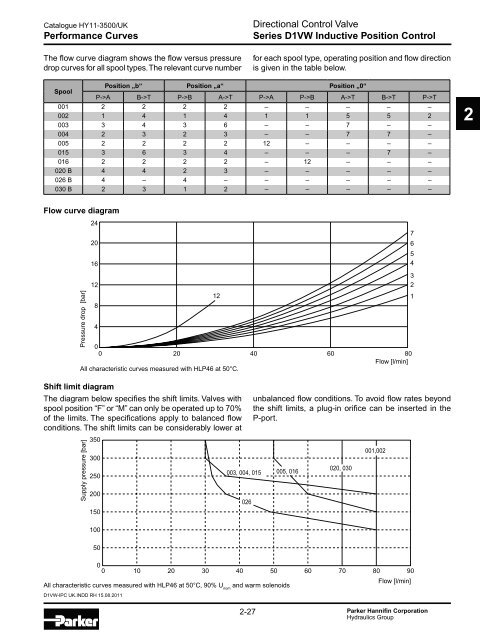
- Page 47 and 48: Catalogue HY11-3500/UK Shift Limits
- Page 49 and 50: Catalogue HY11-3500/UK Notes 2 D1VW
- Page 51 and 52: Catalogue HY11-3500/UK Ordering Cod
- Page 53 and 54: Catalogue HY11-3500/UK Flow Curve D
- Page 55 and 56: Catalogue HY11-3500/UK Dimensions D
- Page 57 and 58: Catalogue HY11-3500/UK Ordering Cod
- Page 59 and 60: Catalogue HY11-3500/UK Flow Curve D
- Page 61 and 62: 2 Catalogue HY11-3500/UK Shift Limi
- Page 63 and 64: Catalogue HY11-3500/UK Notes 2 D3W
- Page 65 and 66: Catalogue HY11-3500/UK Ordering Cod
- Page 67 and 68: Catalogue HY11-3500/UK Position Con
- Page 69 and 70: Catalogue HY11-3500/UK Dimensions D
- Page 71 and 72: Catalogue HY11-3500/UK Ordering Cod
- Page 73 and 74: Catalogue HY11-3500/UK Flow Curve D
- Page 75 and 76: 30 Catalogue HY11-3500/UK Dimension
- Page 77 and 78: Catalogue HY11-3500/UK Ordering Cod
- Page 79 and 80: Catalogue HY11-3500/UK Ordering Cod
- Page 81 and 82: Catalogue HY11-3500/UK Technical Da
- Page 83 and 84: 2 Catalogue HY11-3500/UK Flow Curve
- Page 85 and 86: Catalogue HY11-3500/UK Pilot Oil Op
- Page 87 and 88: 1cm M10 Catalogue HY11-3500/UK Dime
- Page 89 and 90: Catalogue HY11-3500/UK Notes 2 D3-D
- Page 91 and 92: Catalogue HY11-3500/UK Ordering Cod
- Page 93 and 94:
Catalogue HY11-3500/UK Flow Curve D
- Page 95 and 96:
Catalogue HY11-3500/UK Dimensions R
- Page 97 and 98:
Catalogue HY11-3500/UK Notes 2 D3-D
- Page 99 and 100:
Catalogue HY11-3500/UK Ordering Cod
- Page 101 and 102:
Catalogue HY11-3500/UK Ordering Cod
- Page 103 and 104:
Catalogue HY11-3500/UK Flow Curve D
- Page 105 and 106:
Catalogue HY11-3500/UK Flow Curve D
- Page 107 and 108:
Catalogue HY11-3500/UK Dimensions D
- Page 109 and 110:
Catalogue HY11-3500/UK Notes 2 D_P
- Page 111 and 112:
Catalogue HY11-3500/UK Ordering Cod
- Page 113 and 114:
Catalogue HY11-3500/UK Dimensions D
- Page 115 and 116:
Catalogue HY11-3500/UK Ordering Cod
- Page 117 and 118:
Catalogue HY11-3500/UK Ordering Cod
- Page 119 and 120:
Catalogue HY11-3500/UK Flow Curves
- Page 121 and 122:
Catalogue HY11-3500/UK Dimensions D
- Page 123 and 124:
Catalogue HY11-3500/UK Dimensions D
- Page 125 and 126:
Catalogue HY11-3500/UK Notes 2 D_L
- Page 127 and 128:
Catalogue HY11-3500/UK Actuator Kit
- Page 129 and 130:
Catalogue HY11-3500/UK Slip-In Orif
- Page 131 and 132:
Catalogue HY11-3500/UK Mounting Pat
- Page 133 and 134:
Catalogue HY11-3500/UK Introduction
- Page 135 and 136:
Catalogue HY11-3500/UK Ordering Cod
- Page 137 and 138:
Catalogue HY11-3500/UK Technical Da
- Page 139 and 140:
Catalogue HY11-3500/UK Characterist
- Page 141 and 142:
Catalogue HY11-3500/UK Block Diagra
- Page 143 and 144:
Catalogue HY11-3500/UK Dimensions D
- Page 145 and 146:
Catalogue HY11-3500/UK Notes 3 D1FB
- Page 147 and 148:
Catalogue HY11-3500/UK Ordering Cod
- Page 149 and 150:
Catalogue HY11-3500/UK Technical Da
- Page 151 and 152:
Catalogue HY11-3500/UK Characterist
- Page 153 and 154:
Catalogue HY11-3500/UK Interface Pr
- Page 155 and 156:
Catalogue HY11-3500/UK Dimensions D
- Page 157 and 158:
Catalogue HY11-3500/UK Ordering Cod
- Page 159 and 160:
Catalogue HY11-3500/UK Technical Da
- Page 161 and 162:
Catalogue HY11-3500/UK Characterist
- Page 163 and 164:
Catalogue HY11-3500/UK Wiring Direc
- Page 165 and 166:
3 Catalogue HY11-3500/UK Interface
- Page 167 and 168:
Catalogue HY11-3500/UK Dimensions D
- Page 169 and 170:
Catalogue HY11-3500/UK Regenerative
- Page 171 and 172:
Catalogue HY11-3500/UK Ordering Cod
- Page 173 and 174:
Catalogue HY11-3500/UK Technical Da
- Page 175 and 176:
Catalogue HY11-3500/UK Monitor Swit
- Page 177 and 178:
3 Catalogue HY11-3500/UK Interface
- Page 179 and 180:
Catalogue HY11-3500/UK Dimensions P
- Page 181 and 182:
Catalogue HY11-3500/UK Dimensions P
- Page 183 and 184:
Catalogue HY11-3500/UK Dimensions P
- Page 185 and 186:
Catalogue HY11-3500/UK Ordering Cod
- Page 187 and 188:
Catalogue HY11-3500/UK Technical Da
- Page 189 and 190:
Catalogue HY11-3500/UK Block Diagra
- Page 191 and 192:
Catalogue HY11-3500/UK Dimensions P
- Page 193 and 194:
Catalogue HY11-3500/UK Dimensions P
- Page 195 and 196:
Catalogue HY11-3500/UK Ordering Cod
- Page 197 and 198:
Catalogue HY11-3500/UK Electronics
- Page 199 and 200:
Catalogue HY11-3500/UK Pilot Flow P
- Page 201 and 202:
Catalogue HY11-3500/UK Dimensions P
- Page 203 and 204:
Catalogue HY11-3500/UK Regenerative
- Page 205 and 206:
Catalogue HY11-3500/UK Technical Da
- Page 207 and 208:
Catalogue HY11-3500/UK Characterist
- Page 209 and 210:
Catalogue HY11-3500/UK Pilot Flow P
- Page 211 and 212:
Catalogue HY11-3500/UK Dimensions P
- Page 213 and 214:
Catalogue HY11-3500/UK Ordering Cod
- Page 215 and 216:
Catalogue HY11-3500/UK Characterist
- Page 217 and 218:
Catalogue HY11-3500/UK Dimensions D
- Page 219 and 220:
Catalogue HY11-3500/UK Ordering Cod
- Page 221 and 222:
3 Catalogue HY11-3500/UK Characteri
- Page 223 and 224:
Catalogue HY11-3500/UK Dimensions D
- Page 225 and 226:
Catalogue HY11-3500/UK Ordering Cod
- Page 227 and 228:
Catalogue HY11-3500/UK Characterist
- Page 229 and 230:
Catalogue HY11-3500/UK Notes 3 D30F
- Page 231 and 232:
Catalogue HY11-3500/UK Regenerative
- Page 233 and 234:
Catalogue HY11-3500/UK Technical Da
- Page 235 and 236:
3 Catalogue HY11-3500/UK Characteri
- Page 237 and 238:
Catalogue HY11-3500/UK Pilot Flow P
- Page 239 and 240:
Catalogue HY11-3500/UK Dimensions P
- Page 241 and 242:
Catalogue HY11-3500/UK Mounting Pat
- Page 243 and 244:
Catalogue HY11-3500/UK Notes 3 Acce
- Page 245 and 246:
Catalogue HY11-3500/UK Notes 4 Cont
- Page 247 and 248:
Catalogue HY11-3500/UK Characterist
- Page 249 and 250:
Catalogue HY11-3500/UK Notes 4 VS U
- Page 251 and 252:
Catalogue HY11-3500/UK Technical Da
- Page 253 and 254:
Catalogue HY11-3500/UK Dimensions D
- Page 255 and 256:
Catalogue HY11-3500/UK Notes 4 VB U
- Page 257 and 258:
Catalogue HY11-3500/UK Ordering Cod
- Page 259 and 260:
Catalogue HY11-3500/UK Dimensions P
- Page 261 and 262:
Catalogue HY11-3500/UK Notes 4 VBY
- Page 263 and 264:
Catalogue HY11-3500/UK Characterist
- Page 265 and 266:
Catalogue HY11-3500/UK Notes 4 EVSA
- Page 267 and 268:
Catalogue HY11-3500/UK Ordering Cod
- Page 269 and 270:
Catalogue HY11-3500/UK Notes 4 R1E0
- Page 271 and 272:
Catalogue HY11-3500/UK Ordering Cod
- Page 273 and 274:
Catalogue HY11-3500/UK Technical Da
- Page 275 and 276:
Catalogue HY11-3500/UK Dimensions P
- Page 277 and 278:
Catalogue HY11-3500/UK Dimensions P
- Page 279 and 280:
Catalogue HY11-3500/UK Notes 4 R4V-
- Page 281 and 282:
Catalogue HY11-3500/UK Ordering Cod
- Page 283 and 284:
Catalogue HY11-3500/UK Characterist
- Page 285 and 286:
Catalogue HY11-3500/UK Characterist
- Page 287 and 288:
Catalogue HY11-3500/UK Dimensions P
- Page 289 and 290:
Catalogue HY11-3500/UK Dimensions P
- Page 291 and 292:
Catalogue HY11-3500/UK Ordering Cod
- Page 293 and 294:
Catalogue HY11-3500/UK Dimensions D
- Page 295 and 296:
Catalogue HY11-3500/UK Technical Da
- Page 297 and 298:
Catalogue HY11-3500/UK Electronics
- Page 299 and 300:
Catalogue HY11-3500/UK Dimensions D
- Page 301 and 302:
Catalogue HY11-3500/UK Ordering Cod
- Page 303 and 304:
Catalogue HY11-3500/UK Characterist
- Page 305 and 306:
Catalogue HY11-3500/UK Dimensions P
- Page 307 and 308:
Catalogue HY11-3500/UK Ordering Cod
- Page 309 and 310:
Catalogue HY11-3500/UK Characterist
- Page 311 and 312:
4 Catalogue HY11-3500/UK Interface
- Page 313 and 314:
Catalogue HY11-3500/UK Dimensions P
- Page 315 and 316:
Catalogue HY11-3500/UK Technical Da
- Page 317 and 318:
Catalogue HY11-3500/UK Characterist
- Page 319 and 320:
Catalogue HY11-3500/UK Dimensions P
- Page 321 and 322:
Catalogue HY11-3500/UK Ordering Cod
- Page 323 and 324:
Catalogue HY11-3500/UK Technical Da
- Page 325 and 326:
Catalogue HY11-3500/UK Dimensions U
- Page 327 and 328:
Catalogue HY11-3500/UK Notes 4 R4U
- Page 329 and 330:
Catalogue HY11-3500/UK Ordering Cod
- Page 331 and 332:
Catalogue HY11-3500/UK Notes 4 R4S
- Page 333 and 334:
Catalogue HY11-3500/UK Ordering Cod
- Page 335 and 336:
Catalogue HY11-3500/UK Dimensions D
- Page 337 and 338:
Catalogue HY11-3500/UK Notes 4 VM U
- Page 339 and 340:
Catalogue HY11-3500/UK Ordering Cod
- Page 341 and 342:
Catalogue HY11-3500/UK Dimensions P
- Page 343 and 344:
Catalogue HY11-3500/UK Ordering Cod
- Page 345 and 346:
Catalogue HY11-3500/UK Characterist
- Page 347 and 348:
Catalogue HY11-3500/UK Characterist
- Page 349 and 350:
Catalogue HY11-3500/UK Dimensions P
- Page 351 and 352:
Catalogue HY11-3500/UK Technical Da
- Page 353 and 354:
Catalogue HY11-3500/UK Dimensions P
- Page 355 and 356:
Catalogue HY11-3500/UK Plugs Pressu
- Page 357 and 358:
Catalogue HY11-3500/UK Notes 5 cont
- Page 359 and 360:
Catalogue HY11-3500/UK Dimensions C
- Page 361 and 362:
Catalogue HY11-3500/UK Dimensions N
- Page 363 and 364:
Catalogue HY11-3500/UK Performance
- Page 365 and 366:
Catalogue HY11-3500/UK Characterist
- Page 367 and 368:
Catalogue HY11-3500/UK Ordering Cod
- Page 369 and 370:
Catalogue HY11-3500/UK Accessories
- Page 371 and 372:
Catalogue HY11-3500/UK Technical Da
- Page 373 and 374:
Catalogue HY11-3500/UK Characterist
- Page 375 and 376:
0 Catalogue HY11-3500/UK Dimensions
- Page 377 and 378:
Catalogue HY11-3500/UK Technical Da
- Page 379 and 380:
Catalogue HY11-3500/UK Accessories
- Page 381 and 382:
Catalogue HY11-3500/UK Notes 6 cont
- Page 383 and 384:
Catalogue HY11-3500/UK Dimensions S
- Page 385 and 386:
Catalogue HY11-3500/UK Characterist
- Page 387 and 388:
Catalogue HY11-3500/UK Notes 6 RK-R
- Page 389 and 390:
Catalogue HY11-3500/UK Characterist
- Page 391 and 392:
Catalogue HY11-3500/UK Performance
- Page 393 and 394:
Catalogue HY11-3500/UK Performance
- Page 395 and 396:
Catalogue HY11-3500/UK Technical Da
- Page 397 and 398:
Catalogue HY11-3500/UK Notes 6 C4V
- Page 399 and 400:
Catalogue HY11-3500/UK Performance
- Page 401 and 402:
Catalogue HY11-3500/UK Ordering Cod
- Page 403 and 404:
Catalogue HY11-3500/UK Notes 6 C4V
- Page 405 and 406:
Catalogue HY11-3500/UK Ordering Cod
- Page 407 and 408:
Catalogue HY11-3500/UK Performance
- Page 409 and 410:
Catalogue HY11-3500/UK Dimensions D
- Page 411 and 412:
Catalogue HY11-3500/UK Ordering Cod
- Page 413 and 414:
Catalogue HY11-3500/UK Ordering Cod
- Page 415 and 416:
Catalogue HY11-3500/UK Notes 6 acce
- Page 417 and 418:
Catalogue HY11-3500/UK Notes 7 cont
- Page 419 and 420:
Catalogue HY11-3500/UK Technical Da
- Page 421 and 422:
Catalogue HY11-3500/UK Dimensions D
- Page 423 and 424:
Catalogue HY11-3500/UK Ordering Cod
- Page 425 and 426:
Catalogue HY11-3500/UK Dimensions R
- Page 427 and 428:
Catalogue HY11-3500/UK Dimensions P
- Page 429 and 430:
Catalogue HY11-3500/UK Characterist
- Page 431 and 432:
Catalogue HY11-3500/UK Ordering Cod
- Page 433 and 434:
Catalogue HY11-3500/UK Ordering Cod
- Page 435 and 436:
Catalogue HY11-3500/UK Performance
- Page 437 and 438:
Catalogue HY11-3500/UK Notes 7 PRDM
- Page 439 and 440:
Catalogue HY11-3500/UK Ordering Cod
- Page 441 and 442:
Catalogue HY11-3500/UK Dimensions P
- Page 443 and 444:
Catalogue HY11-3500/UK Dimensions P
- Page 445 and 446:
Catalogue HY11-3500/UK Dimensions P
- Page 447 and 448:
Catalogue HY11-3500/UK Technical Da
- Page 449 and 450:
Catalogue HY11-3500/UK Ordering Cod
- Page 451 and 452:
Catalogue HY11-3500/UK Technical Da
- Page 453 and 454:
Catalogue HY11-3500/UK Dimensions P
- Page 455 and 456:
Catalogue HY11-3500/UK Technical Da
- Page 457 and 458:
Catalogue HY11-3500/UK Ordering Cod
- Page 459 and 460:
Catalogue HY11-3500/UK Characterist
- Page 461 and 462:
Catalogue HY11-3500/UK Dimensions P
- Page 463 and 464:
Catalogue HY11-3500/UK Ordering Cod
- Page 465 and 466:
Catalogue HY11-3500/UK Performance
- Page 467 and 468:
Catalogue HY11-3500/UK Dimensions T
- Page 469 and 470:
Catalogue HY11-3500/UK Dimensions T
- Page 471 and 472:
Catalogue HY11-3500/UK Technical Da
- Page 473 and 474:
Catalogue HY11-3500/UK Ordering Cod
- Page 475 and 476:
Catalogue HY11-3500/UK Technical Da
- Page 477 and 478:
Catalogue HY11-3500/UK Top Views Di
- Page 479 and 480:
Catalogue HY11-3500/UK Top Views Di
- Page 481 and 482:
Catalogue HY11-3500/UK Characterist
- Page 483 and 484:
Catalogue HY11-3500/UK Ordering Cod
- Page 485 and 486:
Catalogue HY11-3500/UK Technical Da
- Page 487 and 488:
Catalogue HY11-3500/UK Dimensions P
- Page 489 and 490:
Catalogue HY11-3500/UK Notes 7 CPOM
- Page 491 and 492:
Catalogue HY11-3500/UK Characterist
- Page 493 and 494:
Catalogue HY11-3500/UK Notes 7 ZRE
- Page 495 and 496:
Catalogue HY11-3500/UK Characterist
- Page 497 and 498:
Catalogue HY11-3500/UK Ordering Cod
- Page 499 and 500:
Catalogue HY11-3500/UK General Info
- Page 501 and 502:
Catalogue HY11-3500/UK Notes 8 cont
- Page 503 and 504:
Catalogue HY11-3500/UK Dimensions C
- Page 505 and 506:
Catalogue HY11-3500/UK Characterist
- Page 507 and 508:
Catalogue HY11-3500/UK Technical Da
- Page 509 and 510:
Catalogue HY11-3500/UK Ordering Cod
- Page 511 and 512:
Catalogue HY11-3500/UK Ordering Cod
- Page 513 and 514:
Catalogue HY11-3500/UK Dimensions 2
- Page 515 and 516:
Catalogue HY11-3500/UK Ordering Cod
- Page 517 and 518:
Catalogue HY11-3500/UK Ordering Cod
- Page 519 and 520:
Catalogue HY11-3500/UK Pilot Valves
- Page 521 and 522:
Catalogue HY11-3500/UK Pilot Valves
- Page 523 and 524:
Catalogue HY11-3500/UK Pilot Valves
- Page 525 and 526:
Catalogue HY11-3500/UK Pilot Valves
- Page 527 and 528:
Catalogue HY11-3500/UK Cover-, Sand
- Page 529 and 530:
Catalogue HY11-3500/UK Orifice Diag
- Page 531 and 532:
Catalogue HY11-3500/UK Notes 8 Spar
- Page 533 and 534:
Catalogue HY11-3500/UK Ordering Cod
- Page 535 and 536:
Catalogue HY11-3500/UK Characterist
- Page 537 and 538:
Catalogue HY11-3500/UK Dimensions P
- Page 539 and 540:
Catalogue HY11-3500/UK Ordering Cod
- Page 541 and 542:
Catalogue HY11-3500/UK Dimensions P
- Page 543 and 544:
Catalogue HY11-3500/UK Technical Da
- Page 545 and 546:
Catalogue HY11-3500/UK Electronics
- Page 547 and 548:
Catalogue HY11-3500/UK Dimensions P
- Page 549 and 550:
Catalogue HY11-3500/UK Ordering Cod
- Page 551 and 552:
Catalogue HY11-3500/UK Characterist
- Page 553 and 554:
Catalogue HY11-3500/UK Dimensions U
- Page 555 and 556:
Catalogue HY11-3500/UK Pressure Rel
- Page 557 and 558:
Catalogue HY11-3500/UK Pressure Rel
- Page 559 and 560:
Catalogue HY11-3500/UK Pressure Rel
- Page 561 and 562:
Catalogue HY11-3500/UK Pressure Rel
- Page 563 and 564:
Catalogue HY11-3500/UK Unloading Fu
- Page 565 and 566:
Catalogue HY11-3500/UK Unloading Fu
- Page 567 and 568:
Catalogue HY11-3500/UK Pressure Com
- Page 569 and 570:
Catalogue HY11-3500/UK Pressure Com
- Page 571 and 572:
Catalogue HY11-3500/UK Pressure Com
- Page 573 and 574:
Catalogue HY11-3500/UK Technical Da
- Page 575 and 576:
Catalogue HY11-3500/UK Dimensions V
- Page 577 and 578:
Catalogue HY11-3500/UK Ordering Cod
- Page 579 and 580:
Catalogue HY11-3500/UK Notes 8 TEA
- Page 581 and 582:
Catalogue HY11-3500/UK Ordering Cod
- Page 583 and 584:
Catalogue HY11-3500/UK Installation
- Page 585 and 586:
Catalogue HY11-3500/UK Dimensions P
- Page 587 and 588:
Catalogue HY11-3500/UK Dimensions P
- Page 589 and 590:
Catalogue HY11-3500/UK Notes 8 TDP
- Page 591 and 592:
Catalogue HY11-3500/UK Ordering Cod
- Page 593 and 594:
Catalogue HY11-3500/UK Electronics
- Page 595 and 596:
Catalogue HY11-3500/UK Dimensions P
- Page 597 and 598:
Catalogue HY11-3500/UK Dimensions P
- Page 599 and 600:
Catalogue HY11-3500/UK Notes 8 TPQ
- Page 601 and 602:
Catalogue HY11-3500/UK Performance
- Page 603 and 604:
Catalogue HY11-3500/UK Ordering Cod
- Page 605 and 606:
Catalogue HY11-3500/UK Notes 8 SVLB
- Page 607 and 608:
Catalogue HY11-3500/UK 2 Way Functi
- Page 609 and 610:
Catalogue HY11-3500/UK 2 Way Functi
- Page 611 and 612:
Catalogue HY11-3500/UK Notes 8 Exam
- Page 613 and 614:
Catalogue HY11-3500/UK Ordering Cod
- Page 615 and 616:
Catalogue HY11-3500/UK Flow Diagram
- Page 617 and 618:
Catalogue HY11-3500/UK Position Con
- Page 619 and 620:
Catalogue HY11-3500/UK Notes 8 C10
- Page 621 and 622:
Catalogue HY11-3500/UK Technical Da
- Page 623 and 624:
Catalogue HY11-3500/UK Position Con
- Page 625 and 626:
Catalogue HY11-3500/UK Ordering Cod
- Page 627 and 628:
Catalogue HY11-3500/UK Dimensions /
- Page 629 and 630:
Catalogue HY11-3500/UK Notes 9 cont
- Page 631 and 632:
Catalogue HY11-3500/UK Ordering Cod
- Page 633 and 634:
Catalogue HY11-3500/UK Dimensions P
- Page 635 and 636:
Catalogue HY11-3500/UK Dimensions P
- Page 637 and 638:
Catalogue HY11-3500/UK Ordering Cod
- Page 639 and 640:
Catalogue HY11-3500/UK Dimensions P
- Page 641 and 642:
Catalogue HY11-3500/UK Notes 9 R5U
- Page 643 and 644:
Catalogue HY11-3500/UK Ordering Cod
- Page 645 and 646:
Catalogue HY11-3500/UK Dimensions P
- Page 647 and 648:
Catalogue HY11-3500/UK Ordering Cod
- Page 649 and 650:
Catalogue HY11-3500/UK Characterist
- Page 651 and 652:
Catalogue HY11-3500/UK Dimensions P
- Page 653 and 654:
Catalogue HY11-3500/UK Ordering Cod
- Page 655 and 656:
Catalogue HY11-3500/UK Characterist
- Page 657 and 658:
Catalogue HY11-3500/UK Dimensions P
- Page 659 and 660:
Catalogue HY11-3500/UK Technical Da
- Page 661 and 662:
Catalogue HY11-3500/UK Dimensions P
- Page 663 and 664:
Catalogue HY11-3500/UK Ordering Cod
- Page 665 and 666:
Catalogue HY11-3500/UK Characterist
- Page 667 and 668:
Catalogue HY11-3500/UK Dimensions D
- Page 669 and 670:
Catalogue HY11-3500/UK D5S with Pos
- Page 671 and 672:
Catalogue HY11-3500/UK Ordering Cod
- Page 673 and 674:
Catalogue HY11-3500/UK Ordering Cod
- Page 675 and 676:
Catalogue HY11-3500/UK Ordering Cod
- Page 677 and 678:
Catalogue HY11-3500/UK Ordering Cod
- Page 679 and 680:
Catalogue HY11-3500/UK Dimensions P
- Page 681 and 682:
Catalogue HY11-3500/UK Technical Da
- Page 683 and 684:
Catalogue HY11-3500/UK Ordering Cod
- Page 685 and 686:
Catalogue HY11-3500/UK Technical Da
- Page 687 and 688:
Catalogue HY11-3500/UK Dimensions 3
- Page 689 and 690:
Catalogue HY11-3500/UK Notes 9 R5P
- Page 691 and 692:
Catalogue HY11-3500/UK Technical Da
- Page 693 and 694:
Catalogue HY11-3500/UK Dimensions D
- Page 695 and 696:
Catalogue HY11-3500/UK Technical Da
- Page 697 and 698:
Catalogue HY11-3500/UK Dimensions P
- Page 699 and 700:
Catalogue HY11-3500/UK Flanges SAE
- Page 701 and 702:
Catalogue HY11-3500/UK Notes 9 acce
- Page 703 and 704:
Catalogue HY11-3500/UK Notes 10 Con
- Page 705 and 706:
Catalogue HY11-3500/UK Ordering Cod
- Page 707 and 708:
Catalogue HY11-3500/UK Characterist
- Page 709 and 710:
Catalogue HY11-3500/UK Dimensions P
- Page 711 and 712:
Catalogue HY11-3500/UK Ordering Cod
- Page 713 and 714:
Catalogue HY11-3500/UK Characterist
- Page 715 and 716:
Catalogue HY11-3500/UK Dimensions P
- Page 717 and 718:
Catalogue HY11-3500/UK Ordering Cod
- Page 719 and 720:
Catalogue HY11-3500/UK Dimensions P
- Page 721 and 722:
Catalogue HY11-3500/UK Notes 10 R4V
- Page 723 and 724:
Catalogue HY11-3500/UK Technical Da
- Page 725 and 726:
Catalogue HY11-3500/UK Dimensions P
- Page 727 and 728:
Catalogue HY11-3500/UK Notes 10 R4R
- Page 729 and 730:
Catalogue HY11-3500/UK Ordering Cod
- Page 731 and 732:
Catalogue HY11-3500/UK Characterist
- Page 733 and 734:
Catalogue HY11-3500/UK Dimensions D
- Page 735 and 736:
Catalogue HY11-3500/UK Ordering Cod
- Page 737 and 738:
Catalogue HY11-3500/UK Notes 10 D4S
- Page 739 and 740:
Catalogue HY11-3500/UK Dimensions N
- Page 741 and 742:
Catalogue HY11-3500/UK Characterist
- Page 743 and 744:
Catalogue HY11-3500/UK Characterist
- Page 745 and 746:
Catalogue HY11-3500/UK Characterist
- Page 747 and 748:
Catalogue HY11-3500/UK Characterist
- Page 749 and 750:
Catalogue HY11-3500/UK Characterist
- Page 751 and 752:
Catalogue HY11-3500/UK Ordering Cod
- Page 753 and 754:
Catalogue HY11-3500/UK Notes 10 RH
- Page 755 and 756:
Catalogue HY11-3500/UK Notes 10 acc
- Page 757 and 758:
Catalogue HY11-3500/UK Notes 11 Con
- Page 759 and 760:
Catalogue HY11-3500/UK Technical Da
- Page 761 and 762:
Catalogue HY11-3500/UK Interface Pr
- Page 763 and 764:
Catalogue HY11-3500/UK Technical Da
- Page 765 and 766:
Catalogue HY11-3500/UK Interface Pr
- Page 767 and 768:
Catalogue HY11-3500/UK Technical Da
- Page 769 and 770:
Catalogue HY11-3500/UK Interface Pr
- Page 771 and 772:
Catalogue HY11-3500/UK Technical Da
- Page 773 and 774:
Catalogue HY11-3500/UK Interface Pr
- Page 775 and 776:
Catalogue HY11-3500/UK Technical Da
- Page 777 and 778:
Catalogue HY11-3500/UK Interface Pr
- Page 779 and 780:
Catalogue HY11-3500/UK Ordering Cod
- Page 781 and 782:
Catalogue HY11-3500/UK General Proj
- Page 783 and 784:
Catalogue HY11-3500/UK Technology F
- Page 785 and 786:
Catalogue HY11-3500/UK Technology F
- Page 787 and 788:
Catalogue HY11-3500/UK Technology F
- Page 789 and 790:
Catalogue HY11-3500/UK Software Too
- Page 791 and 792:
Catalogue HY11-3500/UK Software Too
- Page 793 and 794:
Catalogue HY11-3500/UK Accessories
- Page 795 and 796:
Catalogue HY11-3500/UK Accessories
- Page 797 and 798:
Catalogue HY11-3500/UK Block Diagra
- Page 799 and 800:
Catalogue HY11-3500/UK Operation Te
- Page 801 and 802:
Catalogue HY11-3500/UK Notes 12 con
- Page 803 and 804:
Catalogue HY11-3500/UK Characterist
- Page 805 and 806:
Catalogue HY11-3500/UK Characterist
- Page 807 and 808:
Catalogue HY11-3500/UK Characterist
- Page 809 and 810:
Catalogue HY11-3500/UK Characterist
- Page 811 and 812:
Catalogue HY11-3500/UK Characterist
- Page 813 and 814:
Catalogue HY11-3500/UK Dimensions M
- Page 815 and 816:
Catalogue HY11-3500/UK Dimensions M
- Page 817 and 818:
Catalogue HY11-3500/UK Dimensions M
- Page 819 and 820:
Catalogue HY11-3500/UK Notes 12 MSP
- Page 821 and 822:
Catalogue HY11-3500/UK Cover-, Sand
- Page 823 and 824:
Catalogue HY11-3500/UK Notes 12 PAD
- Page 825 and 826:
Catalogue HY11-3500/UK Characterist
- Page 827 and 828:
S Catalogue HY11-3500/UK Characteri
- Page 829 and 830:
Catalogue HY11-3500/UK Characterist
- Page 831 and 832:
Catalogue HY11-3500/UK Characterist
- Page 833 and 834:
1 A 2 Catalogue HY11-3500/UK Dimens
- Page 835 and 836:
Catalogue HY11-3500/UK Technical Da
- Page 837 and 838:
Y Y Catalogue HY11-3500/UK Dimensio
- Page 839 and 840:
Y Y Catalogue HY11-3500/UK Performa
- Page 841 and 842:
12 Catalogue HY11-3500/UK Tie Rod K
- Page 843 and 844:
Catalogue HY11-3500/UK Dimensions P
- Page 845 and 846:
Catalogue HY11-3500/UK Technical Da
- Page 847 and 848:
Catalogue HY11-3500/UK Dimensions P
- Page 849 and 850:
Catalogue HY11-3500/UK Notes 12 PSB
- Page 851 and 852:
Catalogue HY11-3500/UK Instrument F
- Page 853 and 854:
Catalogue HY11-3500/UK Connection D
- Page 855 and 856:
Catalogue HY11-3500/UK Ordering Cod
- Page 857 and 858:
Catalogue HY11-3500/UK Technical Da
- Page 859 and 860:
Catalogue HY11-3500/UK Accessories
- Page 861 and 862:
Catalogue HY11-3500/UK Notes 12 SD5


