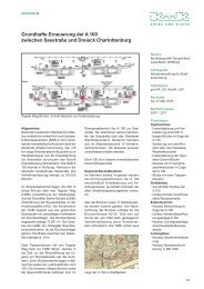
Planning of the ship lift at the Three - Krebs und Kiefer, Beratende ...
Planning of the ship lift at the Three - Krebs und Kiefer, Beratende ...
Planning of the ship lift at the Three - Krebs und Kiefer, Beratende ...

You also want an ePaper? Increase the reach of your titles
YUMPU automatically turns print PDFs into web optimized ePapers that Google loves.
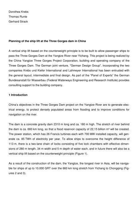
Doro<strong>the</strong>a <strong>Krebs</strong><br />
Thomas Runte<br />
Gerhard Strack<br />
<strong>Planning</strong> <strong>of</strong> <strong>the</strong> <strong>ship</strong> <strong>lift</strong> <strong>at</strong> <strong>the</strong> <strong>Three</strong> Gorges dam in China<br />
A vertical <strong>ship</strong> <strong>lift</strong> based on <strong>the</strong> counterweight principle is to be built to allow passenger <strong>ship</strong>s to<br />
pass <strong>the</strong> <strong>Three</strong> Gorges Dam <strong>at</strong> <strong>the</strong> Yangtze River near Yichang. This project is being realized by<br />
<strong>the</strong> China Yangtze <strong>Three</strong> Gorges Project Corpor<strong>at</strong>ion, building and oper<strong>at</strong>ing company <strong>of</strong> <strong>the</strong><br />
<strong>Three</strong> Gorges Dam. The German joint venture, "German Design Group", incorpor<strong>at</strong>ing <strong>the</strong> two<br />
companies <strong>Krebs</strong> <strong>und</strong> <strong>Kiefer</strong> Intern<strong>at</strong>ional and Lahmeyer Intern<strong>at</strong>ional has been entrusted with<br />
<strong>the</strong> general layout, intermedi<strong>at</strong>e and final design. As part <strong>of</strong> <strong>the</strong> “Panel <strong>of</strong> Experts” <strong>the</strong> German<br />
B<strong>und</strong>esanstalt für Wasserbau (Federal W<strong>at</strong>erways Engineering and Research Institute) provides<br />
consulting support to <strong>the</strong> building company.<br />
1 Introduction<br />
China’s objectives in <strong>the</strong> <strong>Three</strong> Gorges Dam project on <strong>the</strong> Yangtze River are to gener<strong>at</strong>e elec-<br />
trical energy, to protect densely popul<strong>at</strong>ed areas from flooding and to improve conditions for<br />
navig<strong>at</strong>ion on <strong>the</strong> river.<br />
The dam is a concrete gravity dam 2310 m long and ca. 180 m high. The stretch <strong>of</strong> river behind<br />
<strong>the</strong> dam is ca. 660 km long, so th<strong>at</strong> a flood reservoir capacity <strong>of</strong> 22,15 billion m³ will be cre<strong>at</strong>ed.<br />
The power st<strong>at</strong>ion, which has 26 Francis turbines each with 700 MW installed capacity, will gen-<br />
er<strong>at</strong>e ca. 85 TWh <strong>of</strong> electricity per year. To allow <strong>ship</strong>s to overcome <strong>the</strong> height difference <strong>of</strong><br />
113 m, <strong>the</strong>re is a two-lane chain <strong>of</strong> locks consisting <strong>of</strong> five lock chambers with effective dimen-<br />
sions <strong>of</strong> 280 m length, 34 m width and 5 m depth <strong>of</strong> w<strong>at</strong>er each, and in future <strong>the</strong>re will also be a<br />
vertical <strong>ship</strong> <strong>lift</strong> based on <strong>the</strong> counterweight principle (Figure 1).<br />
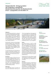
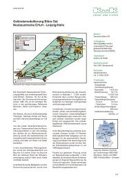
As a result <strong>of</strong> <strong>the</strong> construction <strong>of</strong> <strong>the</strong> dam, <strong>the</strong> Yangtze, <strong>the</strong> longest river in Asia, will be naviga-<br />
ble for <strong>ship</strong>s <strong>of</strong> up to 10.000 GRT over <strong>the</strong> 660 km long stretch from Yichang to Chongqing (Fig-<br />
ures 2 and 3).
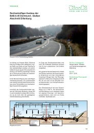
After completion <strong>of</strong> <strong>the</strong> entire project, goods <strong>ship</strong>s will pass through <strong>the</strong> five-chamber lock chain<br />
(already in oper<strong>at</strong>ion), a process th<strong>at</strong> takes ca. 3 hours (Figure 4). Passenger <strong>ship</strong>s will be<br />
transported by <strong>the</strong> <strong>ship</strong> <strong>lift</strong> in a much shorter journey time <strong>of</strong> aro<strong>und</strong> one hour (<strong>the</strong> actual <strong>lift</strong>ing<br />
time is a maximum <strong>of</strong> 21 minutes <strong>at</strong> a <strong>lift</strong>ing speed <strong>of</strong> 0,2 m/s).<br />
The <strong>ship</strong> <strong>lift</strong> in <strong>the</strong> <strong>Three</strong> Gorges Project has special constructional characteristics th<strong>at</strong> are sig-<br />
nificantly different from those <strong>of</strong> all known <strong>ship</strong> <strong>lift</strong>s built up to now [1] (Table 1):<br />
- <strong>the</strong> maximum <strong>lift</strong>ing height <strong>of</strong> 113 m is aro<strong>und</strong> three times th<strong>at</strong> <strong>of</strong> German <strong>ship</strong> <strong>lift</strong>s,<br />
- <strong>the</strong> chamber dimensions and <strong>the</strong>refore <strong>the</strong> weights to be moved using <strong>the</strong> counterweight prin-<br />
ciple (ca. 34000 t) are gre<strong>at</strong>er than in any <strong>ship</strong> <strong>lift</strong>s built up to now,<br />
- as part <strong>of</strong> an enormous dam complex with power st<strong>at</strong>ions, flood protection and two chains <strong>of</strong><br />
locks, <strong>the</strong> <strong>ship</strong> <strong>lift</strong> is subject to short-term oper<strong>at</strong>ional w<strong>at</strong>er level fluctu<strong>at</strong>ions <strong>of</strong> up to 50 cm<br />
per hour on <strong>the</strong> downstream side,<br />
- hydrological w<strong>at</strong>er level fluctu<strong>at</strong>ions <strong>of</strong> 30 m on <strong>the</strong> upstream side and 11,8 m on <strong>the</strong> down-<br />
stream side require special construction measures <strong>at</strong> <strong>the</strong> upper and lower bays,<br />
- since <strong>the</strong> <strong>ship</strong> <strong>lift</strong> is primarily for use by passenger <strong>ship</strong>s, particularly high safety standards are<br />
required.<br />
2 Initi<strong>at</strong>ion <strong>of</strong> <strong>the</strong> project<br />
Germany has long-term experience <strong>of</strong> <strong>the</strong> construction and oper<strong>at</strong>ion <strong>of</strong> vertical <strong>ship</strong> <strong>lift</strong>s [4]. The<br />
first vertical <strong>ship</strong> <strong>lift</strong> to be mentioned in documents was loc<strong>at</strong>ed <strong>at</strong> <strong>the</strong> Freiberger Mulde near<br />
Halsbrücke in Saxony and allowed ore carrier with dimensions <strong>of</strong> 18 m x 2 m to be raised and<br />
lowered over a height <strong>of</strong> 8 m using <strong>the</strong> ‘dry method’. Today, four vertical <strong>ship</strong> <strong>lift</strong>s with <strong>lift</strong>ing<br />
heights between 13 m and 38 m are in oper<strong>at</strong>ion in Germany. An additional new <strong>ship</strong> <strong>lift</strong> <strong>at</strong> Nied-<br />
erfinow on <strong>the</strong> Havel-Oder W<strong>at</strong>erway near Eberswalde, with a <strong>lift</strong>ing height <strong>of</strong> 36 m is being<br />
planned by <strong>the</strong> w<strong>at</strong>er and navig<strong>at</strong>ion authorities and is currently in <strong>the</strong> tender planning phase. It<br />
will supplement an existing <strong>ship</strong> <strong>lift</strong> constructed in 1936 which, even today, is still remarkable for<br />
its robustness. The dimensions <strong>of</strong> <strong>the</strong> chamber <strong>of</strong> <strong>the</strong> new Niederfinow <strong>ship</strong> <strong>lift</strong> have been de-<br />
signed for modern <strong>ship</strong>s. Its supporting structure is made <strong>of</strong> reinforced concrete, while <strong>the</strong> main<br />
supporting structure <strong>of</strong> <strong>the</strong> existing <strong>ship</strong> <strong>lift</strong> is made <strong>of</strong> steel. The owner and planner is <strong>the</strong><br />
Wasserstraßen-Neubauamt (<strong>of</strong>fice for <strong>the</strong> construction <strong>of</strong> new w<strong>at</strong>erways), Berlin.<br />
The B<strong>und</strong>esanstalt für Wasserbau, Karlsruhe (German Federal W<strong>at</strong>erways Engineering and Re-<br />
search Institute, referred to in this article as <strong>the</strong> BAW) supported <strong>the</strong> planning process with ad-
vice, especially on <strong>the</strong> choice <strong>of</strong> <strong>the</strong> safety and drive systems for <strong>the</strong> <strong>lift</strong> chamber. These plans<br />
became known to <strong>the</strong> owner and oper<strong>at</strong>or <strong>of</strong> <strong>the</strong> <strong>Three</strong> Gorges Dam, <strong>the</strong> China <strong>Three</strong> Gorges<br />
Project Corpor<strong>at</strong>ion (CTGPC). In l<strong>at</strong>e 1999, CTGPC commissioned <strong>the</strong> BAW to carry out a fea-<br />
sibility study [2] on <strong>the</strong> drive and safety systems for <strong>the</strong> planned <strong>ship</strong> <strong>lift</strong> in China [3]. The feasi-<br />
bility study also covered <strong>the</strong> chamber, hydraulic steel construction aspects and hydraulic sys-<br />
tems, as well as earthquake consider<strong>at</strong>ions. The feasibility study, <strong>und</strong>er BAW leader<strong>ship</strong>, in-<br />
volved a number <strong>of</strong> engineering firms which had taken part in <strong>the</strong> preliminary planning for <strong>the</strong><br />
new Niederfinow <strong>ship</strong> <strong>lift</strong> (<strong>Krebs</strong> <strong>und</strong> <strong>Kiefer</strong>, Germanische Lloyd, Spezialbau Engineering<br />
GmbH).<br />
Based on assessments <strong>of</strong> <strong>the</strong> drives used in existing <strong>ship</strong> <strong>lift</strong>s in Germany and in o<strong>the</strong>r countries,<br />
e.g. rope winch drive (Strépy Thieu), too<strong>the</strong>d rack and pinion (Lüneburg), nut with driven spindle<br />
(Henrichenburg), spindle with driven nut (Ro<strong>the</strong>nsee) and pinion rack and pinion (old <strong>lift</strong> <strong>at</strong> Nied-<br />
erfinow), pinion drive was selected as <strong>the</strong> preferred altern<strong>at</strong>ive for <strong>the</strong> new <strong>Three</strong> Gorges <strong>ship</strong><br />
<strong>lift</strong>. The assessment <strong>of</strong> <strong>the</strong> different safety systems, which are closely linked with <strong>the</strong> drives, e.g.<br />
drum brake (Strépy Thieu), nut post (old <strong>lift</strong> <strong>at</strong> Niederfinow, Lüneburg) and lock nut on spindle<br />
(Henrichenburg, Ro<strong>the</strong>nsee), favored <strong>the</strong> nut post as <strong>the</strong> most reliable safety system [3]. Both<br />
principles show parallels with <strong>the</strong> newly planned <strong>ship</strong> <strong>lift</strong> <strong>at</strong> Niederfinow.<br />
Pinion drives are characterized by <strong>the</strong>ir gre<strong>at</strong> robustness. The <strong>ship</strong> chamber safety mechanism<br />
is <strong>of</strong> particular importance. At any height, it prevents uncontrollable working conditions th<strong>at</strong> could<br />
arise as a result <strong>of</strong> accidents by safely locking <strong>the</strong> chamber onto <strong>the</strong> concrete structure. Acciden-<br />
tal loads can occur, for instance, if <strong>the</strong> chamber is unexpectedly emptied (partially or com-<br />
pletely). W<strong>at</strong>er losses <strong>of</strong> this type are usually caused by major leaks in <strong>the</strong> chamber seals or by<br />
damage to <strong>the</strong> chamber. Ano<strong>the</strong>r typical design consider<strong>at</strong>ion is chamber up<strong>lift</strong> in <strong>the</strong> lower posi-<br />
tion in <strong>the</strong> case <strong>of</strong> a chamber basement th<strong>at</strong> has filled with w<strong>at</strong>er, e.g. as a result <strong>of</strong> unusually<br />
high w<strong>at</strong>er levels. In <strong>the</strong> <strong>ship</strong> <strong>lift</strong>s <strong>at</strong> Lüneburg and Niederfinow, <strong>the</strong> chamber safety mechanisms<br />
have always worked perfectly in <strong>the</strong>se unusual load cases.<br />
Following intensive scrutiny <strong>of</strong> <strong>the</strong> study, CTGPC made a decision in favor <strong>of</strong> <strong>the</strong> solutions sug-<br />
gested in <strong>the</strong> feasibility study. Additional engineering firms had, by <strong>the</strong>n, been integr<strong>at</strong>ed into <strong>the</strong><br />
next planning phases for <strong>the</strong> Niederfinow <strong>ship</strong> <strong>lift</strong>, and <strong>at</strong> CTGPC’s request, <strong>the</strong> entire German<br />
engineering expertise on <strong>ship</strong> <strong>lift</strong>s was to be concentr<strong>at</strong>ed in <strong>the</strong> tender planning phase for <strong>the</strong><br />
Chinese <strong>lift</strong> (Figure 5).
For this purpose, <strong>the</strong> two engineering firms <strong>Krebs</strong> <strong>und</strong> <strong>Kiefer</strong> Intern<strong>at</strong>ional and Lahmeyer Inter-<br />
n<strong>at</strong>ional had joined forces to form a project-specific joint venture named "German Design<br />
Group". Specialist planners were engaged as subcontractors for <strong>the</strong> areas <strong>of</strong> mechanical and<br />
electrical engineering and for control equipment technology. Germanischer Lloyd was integr<strong>at</strong>ed<br />
into <strong>the</strong> joint venture as a consultant on safety and oper<strong>at</strong>ions.<br />
The BAW construction department supported <strong>the</strong> owner as a panel <strong>of</strong> expert.<br />
3 Project processing by <strong>the</strong> joint venture<br />
Contract negoti<strong>at</strong>ions between <strong>the</strong> joint venture and <strong>the</strong> Chinese owner CTGPC were success-<br />
fully completed in April 2004 (Figure 5). The subject <strong>of</strong> <strong>the</strong> engineering contract, which is based<br />
on <strong>the</strong> FIDIC standard contract, is <strong>the</strong> production <strong>of</strong> planning documents in English suitable for<br />
use in <strong>the</strong> tender process. This planning work should be completed in Spring 2006.<br />
The planning work is divided into four phases:<br />
- Phase A Familiariz<strong>at</strong>ion with <strong>the</strong> project<br />
- Phase B General Layout<br />
- Phase C Preliminary Design<br />
- Phase D Final/ Tender Design<br />
The basic design principles were summarized in cooper<strong>at</strong>ion with CTGPC in a document entitled<br />
"Guideline for Design" [5]. This covers project-specific regul<strong>at</strong>ions, actions and m<strong>at</strong>erials.<br />
The drawings and specific<strong>at</strong>ions produced in Phase D will enable <strong>the</strong> successful bidders to pro-<br />
duce <strong>the</strong> shop drawings and <strong>the</strong>n to carry out <strong>the</strong> actual construction. As a rule, <strong>the</strong> design and<br />
construction should conform to current German standards.<br />
At <strong>the</strong> end <strong>of</strong> every planning phase, <strong>the</strong> Chinese side reviews <strong>the</strong> planning results and approves<br />
<strong>the</strong>m as <strong>the</strong> basis for <strong>the</strong> next stage <strong>of</strong> planning.<br />
4 Concrete structure<br />
The supporting structure <strong>of</strong> <strong>the</strong> <strong>ship</strong> <strong>lift</strong> is made <strong>of</strong> reinforced concrete. Its overall dimensions are<br />
119 m long, 169 m high and 57,8 m wide (Figures 6 and 7).
Passenger <strong>ship</strong>s are transported vertically in <strong>the</strong> center between <strong>the</strong> reinforced concrete con-<br />
struction. The huge longitudinal shear walls have openings to allow maximum n<strong>at</strong>ural lighting<br />
and ventil<strong>at</strong>ion, which would be especially relevant in <strong>the</strong> case <strong>of</strong> a fire.<br />
On each <strong>of</strong> <strong>the</strong> long sides <strong>of</strong> <strong>the</strong> chamber <strong>the</strong>re is a pair <strong>of</strong> towers. There is a clear distance <strong>of</strong><br />
20 m between <strong>the</strong> towers in each pair. The towers are spanned <strong>at</strong> <strong>the</strong> top by a 21 m high sheave<br />
hall made <strong>of</strong> steel (Figure 8) and are additionally connected with each o<strong>the</strong>r by beams distrib-<br />
uted over <strong>the</strong>ir height. In a longitudinal direction, <strong>the</strong> tops <strong>of</strong> <strong>the</strong> towers are coupled by <strong>the</strong> visitor<br />
pl<strong>at</strong>form and by <strong>the</strong> central control stand (Figure 9).<br />
The chamber is connected with <strong>the</strong> counterweights by ropes th<strong>at</strong> are guided over rope pulleys.<br />
Eight counterweight groups are loc<strong>at</strong>ed on each side <strong>of</strong> <strong>the</strong> chamber, each group being guided<br />
through a reinforced concrete shaft or along <strong>the</strong> side <strong>of</strong> a tower (Figure 10). The reinforced con-<br />
crete shafts measure ca. 10 m by 16 m, and <strong>the</strong> reinforced concrete towers 40 m long and 16 m<br />
wide. The cross-section <strong>of</strong> each tower is composed <strong>of</strong> two l<strong>at</strong>eral shafts and a slightly recessed<br />
area containing <strong>the</strong> elev<strong>at</strong>or and staircase. The too<strong>the</strong>d racks <strong>of</strong> <strong>the</strong> drive and <strong>the</strong> nut post <strong>of</strong> <strong>the</strong><br />
chamber safety mechanism are also installed in this area (Figure 14).<br />
At <strong>the</strong> transition to <strong>the</strong> upper and lower bay respectively, <strong>the</strong>re are individual transverse shear<br />
walls which are stiffened by beams and by <strong>the</strong> ceiling slab <strong>of</strong> <strong>the</strong> sheave hall. A fur<strong>the</strong>r shear<br />
wall is loc<strong>at</strong>ed between each pair <strong>of</strong> towers (Figure 10). These shear walls are required to sup-<br />
port <strong>the</strong> rope pulley beams and also to guide <strong>the</strong> counterweights.<br />
The loads from <strong>the</strong> chamber and <strong>the</strong> counterweights – totaling ca. 320 MN – are transferred into<br />
<strong>the</strong> concrete construction via <strong>the</strong> rope pulley beams <strong>at</strong> <strong>the</strong> top <strong>of</strong> <strong>the</strong> structure (Figure 8). Each<br />
rope pulley beam spans from one transverse wall to <strong>the</strong> next and bears <strong>the</strong> load from one group<br />
<strong>of</strong> counterweights and <strong>the</strong> corresponding share <strong>of</strong> <strong>the</strong> weight <strong>of</strong> <strong>the</strong> chamber. 8 double rope<br />
sheaves with a diameter <strong>of</strong> 5 m are mounted in each field <strong>of</strong> <strong>the</strong> rope pulley beam. The rope<br />
sheaves are protected from external environmental influences by <strong>the</strong> sheave halls. A crane with<br />
a <strong>lift</strong>ing capacity <strong>of</strong> 65 t is installed in each hall so th<strong>at</strong> maintenance work can be carried out.<br />
The supporting walls <strong>of</strong> <strong>the</strong> reinforced concrete structure are mostly 1 m thick. In areas where<br />
concentr<strong>at</strong>ed loads are transferred, <strong>the</strong> walls are thicker.<br />
The concrete construction is designed for a useful life <strong>of</strong> 100 years. The standard areas are con-<br />
structed using concrete <strong>of</strong> Chinese quality C 30, which corresponds to C 25/30. In areas <strong>of</strong> high
loads, Chinese C 35 is used, which practically corresponds to C 30/37. Standard areas are rein-<br />
forced with steel <strong>of</strong> Chinese quality HRB 335 (fyk=335 N/mm²). In areas <strong>of</strong> high loads, HRB 400<br />
(fyk=400 N/mm²) is used.<br />
The fo<strong>und</strong><strong>at</strong>ions <strong>of</strong> <strong>the</strong> reinforced concrete towers are constructed in a 36 m deep excav<strong>at</strong>ion pit<br />
where <strong>the</strong>re is rock (granite) with a stiffness <strong>of</strong> 30.000 MN/m². The calcul<strong>at</strong>ed settlement <strong>und</strong>er<br />
<strong>the</strong> entire load from <strong>the</strong> construction amounts to only a few millimeters. The calcul<strong>at</strong>ions for <strong>the</strong><br />
fo<strong>und</strong><strong>at</strong>ions were made using a half-space model.<br />
5 Steel construction<br />
The 132 m long and 23 m wide steel chamber is built as a self-supporting structure. It hangs<br />
evenly from 128 ropes on each side, 16 ropes for each counterweight group (Figure 11). This<br />
results in a very even transfer <strong>of</strong> loads into <strong>the</strong> chamber. The ends <strong>of</strong> <strong>the</strong> chamber and aro<strong>und</strong><br />
<strong>the</strong> machine rooms are <strong>the</strong> only areas where no ropes can be loc<strong>at</strong>ed, for structural reasons.<br />
The chamber is designed for a w<strong>at</strong>er depth <strong>of</strong> 3,5 m and has a freeboard <strong>of</strong> 80 cm. The clear<br />
distance between <strong>the</strong> fenders is 18 m. The useful distance between <strong>the</strong> anti-collision devices in<br />
front <strong>of</strong> <strong>the</strong> g<strong>at</strong>es is 120 m.<br />
As well as passenger <strong>ship</strong>s with dimensions <strong>of</strong> 84,5 m length, 17,2 m width and a draught <strong>of</strong><br />
2,65 m, <strong>the</strong> chamber is also designed for pushed chains <strong>of</strong> barges <strong>of</strong> length 109,4 m, width 14 m<br />
and draught 2,78 m. The passenger <strong>ship</strong> has a w<strong>at</strong>er displacement <strong>of</strong> 3.000 t.<br />
As well as DIN 19704 Hydraulic steel construction, DIN 18800 and <strong>the</strong> “Guideline for Design“ [5]<br />
were decisive for <strong>the</strong> design <strong>of</strong> <strong>the</strong> chamber.<br />
The chamber construction is an orthotropic pl<strong>at</strong>e. For longitudinal stiffening <strong>und</strong>er <strong>the</strong> floor <strong>of</strong> <strong>the</strong><br />
chamber, open pr<strong>of</strong>iles are used so as not to increase <strong>the</strong> up<strong>lift</strong> th<strong>at</strong> would result from <strong>the</strong> c<strong>at</strong>as-<br />
trophic load case <strong>of</strong> a w<strong>at</strong>er-filled chamber basement. The main beams are 10 m high and 2,3 m<br />
wide three-cell box girders. The choice <strong>of</strong> <strong>the</strong>se very stiff main beams guarantees th<strong>at</strong> <strong>the</strong> entire<br />
construction is stiff enough to ensure th<strong>at</strong> <strong>the</strong> chamber can function properly in all oper<strong>at</strong>ional<br />
situ<strong>at</strong>ions. The box girders have l<strong>at</strong>eral openings to ensure adequ<strong>at</strong>e ventil<strong>at</strong>ion and to reduce<br />
<strong>the</strong> up<strong>lift</strong> volume. The steel construction is made <strong>of</strong> steel <strong>of</strong> Chinese quality Q 345, which is very<br />
similar to German steel quality S 355. The mechanical values for Chinese steel are also reduced<br />
according to <strong>the</strong> sheet thickness, compared with <strong>the</strong> nominal value.
The ropes connect <strong>the</strong> chamber and counterweights. Each counterweight group consists <strong>of</strong><br />
16 individual weights. Each rope connected with <strong>the</strong> chamber is guided over <strong>the</strong> rope sheaves<br />
and connected with one individual weight. This method <strong>of</strong> handling <strong>the</strong> loads ensures th<strong>at</strong> all<br />
ropes bear <strong>the</strong> same load. The 16 individual weights per shaft are combined to form a group us-<br />
ing a safety frame which ensures th<strong>at</strong> each individual weight is prevented from falling if its rope<br />
breaks. The ropes have a nominal strength <strong>of</strong> 1960 N/mm² and a diameter <strong>of</strong> 74 mm.<br />
The machine rooms are loc<strong>at</strong>ed <strong>at</strong> <strong>the</strong> quarter points <strong>of</strong> <strong>the</strong> chamber on both long sides and ex-<br />
tend into <strong>the</strong> concrete towers (Figure 11). The machine rooms house both <strong>the</strong> chamber drive<br />
and <strong>the</strong> chamber safety mechanism (Figure 12). The electrical equipment and controls are lo-<br />
c<strong>at</strong>ed in w<strong>at</strong>ertight rooms in <strong>the</strong> level below <strong>the</strong> drives.<br />
The chamber is closed by a radial lock g<strong>at</strong>e (Figure 13). Each g<strong>at</strong>e segment has a radius <strong>of</strong><br />
3,1 m and is supported l<strong>at</strong>erally in <strong>the</strong> main beams. When <strong>the</strong> g<strong>at</strong>e is open, it disappears into <strong>the</strong><br />
g<strong>at</strong>e niche <strong>at</strong> <strong>the</strong> end <strong>of</strong> <strong>the</strong> chamber and is flush with <strong>the</strong> floor <strong>of</strong> <strong>the</strong> chamber. For inspection<br />
purposes, <strong>the</strong> g<strong>at</strong>e can be moved into an overhead position.<br />
The steel construction is designed for a useful life <strong>of</strong> 70 years, and <strong>the</strong> mechanical components<br />
for a useful life <strong>of</strong> 35 years. For <strong>the</strong> purposes <strong>of</strong> f<strong>at</strong>igue resistance inspections, 335 oper<strong>at</strong>ing<br />
days per year and 22 hours per day are assumed. On average, 18 full journeys (each consisting<br />
<strong>of</strong> an ascent and a descent) per day are planned.<br />
6 Guiding mechanisms<br />
As well as normal oper<strong>at</strong>ing loads, <strong>the</strong> <strong>ship</strong> <strong>lift</strong> is also subject to c<strong>at</strong>astrophic loads, e.g. through<br />
earthquakes. This means th<strong>at</strong> active longitudinal and transverse guidance <strong>of</strong> <strong>the</strong> chamber is<br />
necessary over <strong>the</strong> entire <strong>lift</strong>ing height <strong>of</strong> ca. 113 m to allow controlled movement <strong>of</strong> <strong>the</strong> cham-<br />
ber <strong>und</strong>er normal loads (oper<strong>at</strong>ions) and deliber<strong>at</strong>e load transmission in c<strong>at</strong>astrophic cases. It is<br />
not possible for <strong>the</strong> chamber to swing freely (Figure 14).<br />
The forces resulting from oper<strong>at</strong>ions (e.g. as a result <strong>of</strong> wind) are rel<strong>at</strong>ively minor. Should an<br />
earthquake occur <strong>of</strong> <strong>the</strong> dimensions for which <strong>the</strong> <strong>ship</strong> <strong>lift</strong> was designed, <strong>the</strong> construction must<br />
be in a position to absorb <strong>the</strong> enormous forces (s. Chapter 10).<br />
For cost reasons, <strong>the</strong>re is no separ<strong>at</strong>e guiding equipment for normal oper<strong>at</strong>ions and for <strong>the</strong><br />
c<strong>at</strong>astrophic case <strong>of</strong> an earthquake. The transverse guiding function is integr<strong>at</strong>ed into <strong>the</strong>
too<strong>the</strong>d rack <strong>of</strong> <strong>the</strong> chamber drive, while <strong>the</strong> longitudinal guiding function is combined with <strong>the</strong><br />
earthquake support.<br />
The transverse guiding equipment is loc<strong>at</strong>ed on <strong>the</strong> level <strong>of</strong> <strong>the</strong> electrical equipment rooms be-<br />
ne<strong>at</strong>h <strong>the</strong> machine rooms (Figure 16). The guide carriage grips <strong>the</strong> two guide rails along <strong>the</strong><br />
sides <strong>of</strong> <strong>the</strong> too<strong>the</strong>d rack and can transfer both compressive and tensile forces. A double-acting<br />
hydraulic cylinder with a continuous piston rod is installed on each transverse guide. On both<br />
guide axes, <strong>the</strong> hydraulic cylinders on one side <strong>of</strong> <strong>the</strong> chamber are linked by crossed diagonal<br />
connections with <strong>the</strong> hydraulic cylinders on <strong>the</strong> o<strong>the</strong>r side (Figure 15). This ensures th<strong>at</strong> both<br />
cylinders always move in or out evenly and keeps <strong>the</strong> chamber in a central position between <strong>the</strong><br />
reinforced steel towers. In this way, an expensive additional steering mechanism for <strong>the</strong> cham-<br />
ber could be avoided. The guide carriage moves close to <strong>the</strong> too<strong>the</strong>d rack. The guide rollers are<br />
pre-tensioned for <strong>the</strong> normal oper<strong>at</strong>ional loads. In <strong>the</strong> case <strong>of</strong> an earthquake, <strong>the</strong> roller springs<br />
are fully compressed. The 2 m long runners <strong>of</strong> <strong>the</strong> guide carriage lock because <strong>of</strong> friction and<br />
are able to absorb <strong>the</strong> enormous forces (Figure 16).<br />
The longitudinal guide system has several functions. At <strong>the</strong> holding points, it must be able to ab-<br />
sorb not only <strong>the</strong> w<strong>at</strong>er pressure from <strong>the</strong> g<strong>at</strong>e th<strong>at</strong> is opened on one side (ca. 8 MN) and <strong>the</strong><br />
jacking force from <strong>the</strong> clearance sealing mechanism (ca. 2 MN) but also forces from possible<br />
<strong>ship</strong> impacts. It also takes on forces resulting from earthquakes <strong>of</strong> up to 20 MN. Because <strong>of</strong> <strong>the</strong><br />
necessarily high stiffness <strong>of</strong> <strong>the</strong> reinforced concrete towers and <strong>the</strong> steel chamber, it is very im-<br />
portant th<strong>at</strong> <strong>the</strong> chamber is supported in a constraint-free way. This has been achieved using a<br />
mechanically very simple point support, via a bending beam installed transversely to <strong>the</strong> cham-<br />
ber. This absorbs its loads via a point support in <strong>the</strong> longitudinal axis <strong>of</strong> <strong>the</strong> chamber and trans-<br />
fers <strong>the</strong> loads l<strong>at</strong>erally into <strong>the</strong> reinforced concrete towers by means <strong>of</strong> its stiffness. The steel<br />
girder, a box girder with a cross-section <strong>of</strong> 2 m x 4 m, penetr<strong>at</strong>es <strong>the</strong> main beam bene<strong>at</strong>h <strong>the</strong><br />
floor <strong>of</strong> <strong>the</strong> chamber. Between <strong>the</strong> main beam and <strong>the</strong> reinforced steel construction, <strong>the</strong> bending<br />
beam grips a reinforced concrete projection by means <strong>of</strong> hammer-like construction, and trans-<br />
fers its loads from here evenly to <strong>the</strong> right and to <strong>the</strong> left into <strong>the</strong> reinforced concrete construction<br />
(Figure 17). The middle support for <strong>the</strong> longitudinal guiding system is designed for a load <strong>of</strong> al-<br />
most 30 MN and is an elastomer bearing. Loads from <strong>the</strong> chamber are transferred via <strong>the</strong> cham-<br />
ber floor and via <strong>the</strong> transverse beams which are joined next to <strong>the</strong> bearing by additional steel<br />
sheets to form a box girder. The bearing is installed on a girder-grid-like substructure in order to<br />
be able to transfer <strong>the</strong> concentr<strong>at</strong>ed loads into <strong>the</strong> steel construction. For this purpose, additional<br />
diaphragms between <strong>the</strong> transverse beams are required to ensure spreading <strong>of</strong> <strong>the</strong> loads.
During oper<strong>at</strong>ions, <strong>the</strong>re is a gap <strong>of</strong> 5 mm between <strong>the</strong> longitudinal guide system and <strong>the</strong> guide<br />
rails, which is ensured by pre-tensioned guide rollers.<br />
Through <strong>the</strong> st<strong>at</strong>ically determin<strong>at</strong>e chamber guide system, both <strong>the</strong> reinforced concrete towers<br />
and <strong>the</strong> chamber can deform without constraints. The transverse and longitudinal guide systems<br />
can, each independently <strong>of</strong> <strong>the</strong> o<strong>the</strong>r, transfer <strong>the</strong> loads which arise.<br />
7 Drive<br />
The mass <strong>of</strong> <strong>the</strong> chamber and <strong>the</strong> normal amount <strong>of</strong> w<strong>at</strong>er in it are balanced by <strong>the</strong> counter-<br />
weights. The drive system is designed for a w<strong>at</strong>er level difference <strong>of</strong> 10 cm.<br />
The chamber is driven by four pinions th<strong>at</strong> extend into too<strong>the</strong>d racks built into <strong>the</strong> towers. Each<br />
pinion is elastically mounted on a bearing bracket in <strong>the</strong> machine room in such a way th<strong>at</strong><br />
movements can be compens<strong>at</strong>ed (Figure 18). Because <strong>of</strong> <strong>the</strong> chosen kinem<strong>at</strong>ics <strong>of</strong> <strong>the</strong> mount-<br />
ing, only minor rel<strong>at</strong>ive deform<strong>at</strong>ions between <strong>the</strong> pinion and <strong>the</strong> too<strong>the</strong>d rack result. Guide car-<br />
riages behind <strong>the</strong> too<strong>the</strong>d rack ensure th<strong>at</strong> <strong>the</strong> pinion is always gripped by <strong>the</strong> rack. The pinion is<br />
driven on both sides by shafts, each <strong>of</strong> which is directly connected with an electric motor via driv-<br />
ing gear.<br />
To deal with <strong>the</strong> rare case th<strong>at</strong> one or even both motors <strong>at</strong> a drive st<strong>at</strong>ion are out <strong>of</strong> action, all<br />
drives are connected with each o<strong>the</strong>r by synchronizing shafts <strong>und</strong>er <strong>the</strong> chamber. In this situa-<br />
tion, <strong>the</strong> missing drive moment is transferred to <strong>the</strong> affected area by <strong>the</strong>se shafts, so th<strong>at</strong> <strong>the</strong><br />
chamber journey can be completed as planned.<br />
The chamber is motor-driven on both <strong>the</strong> ascent and descent. On <strong>the</strong> ascent, <strong>the</strong> chamber is<br />
moved with a slightly larger w<strong>at</strong>er level difference. On <strong>the</strong> descent, <strong>the</strong> chamber is slightly less<br />
full, so th<strong>at</strong> <strong>the</strong> counterweights tend to pull it up, and as a result it must be pulled down using<br />
motors. The construction is, however, designed in such a way th<strong>at</strong> <strong>the</strong> <strong>lift</strong> can be oper<strong>at</strong>ed in<br />
gener<strong>at</strong>ing mode. Motor-driven mode leads to altern<strong>at</strong>ing stresses on <strong>the</strong> pinions which were<br />
taken into consider<strong>at</strong>ion in <strong>the</strong> design process.<br />
8 Chamber safety mechanism<br />
By securely locking <strong>the</strong> chamber onto <strong>the</strong> concrete construction, <strong>the</strong> chamber safety mechanism<br />
prevents uncontrollable oper<strong>at</strong>ing situ<strong>at</strong>ions which could o<strong>the</strong>rwise result from accidents. The<br />
chamber safety mechanism is a combin<strong>at</strong>ion <strong>of</strong> a nut post and a rotary Archimedean screw. The<br />
nut post is a cast steel column construction, slit longitudinally and with an internal thread, th<strong>at</strong> is
uilt into <strong>the</strong> concrete construction over <strong>the</strong> entire <strong>lift</strong>ing height. Inside <strong>the</strong> nut post a spindle<br />
moves, revolving aro<strong>und</strong> its own axis. This spindle, for which <strong>the</strong> term rotary Archimedean screw<br />
is also used, is driven directly by <strong>the</strong> chamber drive system. Because <strong>of</strong> a direct mechanical cou-<br />
pling via a shaft system between <strong>the</strong> drives and <strong>the</strong> rotary Archimedean screws <strong>of</strong> <strong>the</strong> chamber<br />
safety mechanism, <strong>the</strong> rotary Archimedean screws always move synchronously with <strong>the</strong> drives<br />
in a force-free way. During normal oper<strong>at</strong>ions, <strong>the</strong>re is a certain amount <strong>of</strong> play between <strong>the</strong> ro-<br />
tary Archimedean screw and <strong>the</strong> nut post, so th<strong>at</strong> <strong>the</strong>y do not touch each o<strong>the</strong>r. The rotary Archi-<br />
medean screw is supported by articul<strong>at</strong>ed rods mounted on <strong>the</strong> upper and lower corner pieces <strong>of</strong><br />
<strong>the</strong> chamber (Figure 19). The upper corner piece is connected with <strong>the</strong> chamber by a pin con-<br />
struction and can be dismantled for repair work on <strong>the</strong> rotary Archimedean screw.<br />
If <strong>the</strong> pinion is overloaded, e.g. by a higher w<strong>at</strong>er level difference or by a loss <strong>of</strong> w<strong>at</strong>er, it deflects<br />
and escapes its load. In such a case, <strong>the</strong> chamber locks into <strong>the</strong> nut post via <strong>the</strong> rotary Archi-<br />
medean screw and is immedi<strong>at</strong>ely stopped.<br />
The nut post is installed over <strong>the</strong> entire height in sections ca. 5 m long. Because <strong>of</strong> <strong>the</strong> very high<br />
degree <strong>of</strong> accuracy required, it is not possible to build it into <strong>the</strong> first stage concrete. Cavities are<br />
<strong>the</strong>refore cre<strong>at</strong>ed in <strong>the</strong> first stage concrete in which steel girders can be embedded in a next<br />
step – after completion <strong>of</strong> <strong>the</strong> towers. The flanges <strong>of</strong> <strong>the</strong> steel girders have block connectors on<br />
<strong>the</strong> side towards <strong>the</strong> nut post and are flush with <strong>the</strong> second stage concrete. This measure con-<br />
siderably increases <strong>the</strong> level <strong>of</strong> accuracy. However, for <strong>the</strong> install<strong>at</strong>ion <strong>of</strong> <strong>the</strong> nut post, this step is<br />
not sufficient. In a final step, <strong>the</strong> nut post, which also has block connectors on its rear side, is<br />
adjusted. The block connectors now engage directly. The joint between <strong>the</strong> block connectors is<br />
designed to compens<strong>at</strong>e for a maximum <strong>of</strong> 2 cm. Following final exact adjustment, <strong>the</strong> joint is<br />
poured using high-strength low-shrinkage mortar. Vertical load transfer now takes place via <strong>the</strong><br />
block connectors. The tensile forces resulting from <strong>the</strong> eccentric load transfer are returned to <strong>the</strong><br />
concrete construction by means <strong>of</strong> screws and tendons.<br />
9 Ship chamber locking mechanism<br />
At its upper and lower holding points, <strong>the</strong> chamber is locked both vertically and horizontally. This<br />
ensures th<strong>at</strong> additional vertical loads, e.g. through a change in <strong>the</strong> w<strong>at</strong>er level, do not lead to<br />
additional loads on <strong>the</strong> driving pinion. Horizontal loads, e.g. from <strong>the</strong> impact <strong>of</strong> a <strong>ship</strong>, can easily<br />
be absorbed in <strong>the</strong> same way.<br />
Vertical locking takes place <strong>at</strong> <strong>the</strong> outermost point <strong>of</strong> each concrete shaft (Figures 14 and 20).<br />
Through a vertical cylinder, two horizontal pincers are positioned in two l<strong>at</strong>eral locking pockets<br />
loc<strong>at</strong>ed in <strong>the</strong> concrete. The pincers are <strong>the</strong>n extended horizontally and pre-tensioned vertically
(Figure 20). For safety reasons, <strong>the</strong> piston <strong>of</strong> <strong>the</strong> vertical cylinder is <strong>the</strong>n blocked so th<strong>at</strong> it can-<br />
not yield even if <strong>the</strong> oil pressure falls.<br />
In a longitudinal direction, <strong>the</strong> chamber is also locked in <strong>the</strong> longitudinal guide via <strong>the</strong> jacking rail.<br />
In <strong>the</strong> jacking rail, <strong>the</strong> longitudinal guide is friction-locked with <strong>the</strong> concrete via an eccentric tap-<br />
pet. Horizontal loads arising from <strong>the</strong> g<strong>at</strong>e th<strong>at</strong> is open on only one side and from possible <strong>ship</strong><br />
impacts can easily be absorbed in this way.<br />
Both <strong>the</strong> <strong>ship</strong> chamber locking mechanism and <strong>the</strong> jacking rail must be capable <strong>of</strong> functioning<br />
over <strong>the</strong> entire 30 m range <strong>of</strong> w<strong>at</strong>er fluctu<strong>at</strong>ion on <strong>the</strong> upstream side (145 m to 175 m). On <strong>the</strong><br />
downstream side, w<strong>at</strong>er level changes <strong>of</strong> up to 11,8 m (62 m to 73,8 m) can occur.<br />
10 Load cases, in particular earthquakes<br />
The concrete components have been reviewed with respect to <strong>the</strong> decisive civil engineering de-<br />
sign situ<strong>at</strong>ions in ZTV-ING and/or <strong>the</strong> DIN specialist reports 100-102, and <strong>the</strong> hydraulic steel<br />
components according to DIN 19704 on <strong>the</strong> basis <strong>of</strong> <strong>the</strong> new norm concept. Additional load<br />
cases were added in <strong>the</strong> basic design principles ("Guideline for design") [5] by agreement with<br />
<strong>the</strong> owner and <strong>the</strong> owner’s advisers, <strong>the</strong> B<strong>und</strong>esanstalt für Wasserbau.<br />
Special load cases must be investig<strong>at</strong>ed in addition to <strong>the</strong> normal load cases like w<strong>at</strong>er filling,<br />
wind loads, traction loads and guiding forces. These cases include impacts from docking <strong>ship</strong>s,<br />
sunken <strong>ship</strong>s, an empty chamber and a <strong>ship</strong> chamber subject to up<strong>lift</strong>. The load case ‘earth-<br />
quake’ is <strong>of</strong> very gre<strong>at</strong> importance for <strong>the</strong> construction. In addition to <strong>the</strong> loads resulting from<br />
moving masses, inform<strong>at</strong>ion about <strong>the</strong> height <strong>of</strong> <strong>the</strong> waves in <strong>the</strong> chamber is significant in order<br />
to be able to judge whe<strong>the</strong>r w<strong>at</strong>er can slosh out <strong>of</strong> <strong>the</strong> chamber [6].<br />
The actions for <strong>the</strong> earthquake load case were defined according to <strong>the</strong> Chinese earthquake<br />
norms for hydraulic structures. The <strong>ship</strong> <strong>lift</strong> is loc<strong>at</strong>ed in Zone VI <strong>of</strong> <strong>the</strong> Mercalli scale (Figure 21).<br />
Because <strong>of</strong> <strong>the</strong> very high safety requirements, <strong>the</strong> construction was designed for Zone VII with a<br />
basic acceler<strong>at</strong>ion <strong>of</strong> 0,1 g (1 m/s²) with a probability <strong>of</strong> occurrence <strong>of</strong> once in 5000 years. Since<br />
no digitally recorded earthquake d<strong>at</strong>a is available for this area, <strong>the</strong> design was based on artificial<br />
earthquake inform<strong>at</strong>ion gener<strong>at</strong>ed by <strong>the</strong> intern<strong>at</strong>ionally recognized SIMQKE program developed<br />
by <strong>the</strong> Massachusetts Institute <strong>of</strong> Technology. The components were designed according to<br />
Eurocode 8 (Figure 22).<br />
The objectives are to ensure th<strong>at</strong> in <strong>the</strong> case <strong>of</strong> an earthquake, <strong>the</strong> safety <strong>of</strong> human life (above<br />
all) is guaranteed and disproportion<strong>at</strong>ely large financial damage is avoided. As a result, only s-<br />
mall rel<strong>at</strong>ive displacements (≈ ± 8-10 cm) are permissible between <strong>the</strong> chamber and <strong>the</strong> guide
system <strong>at</strong>tached to <strong>the</strong> concrete construction. The functioning <strong>of</strong> <strong>the</strong> chamber safety mechanism<br />
must be guaranteed in every oper<strong>at</strong>ional position.<br />
In <strong>the</strong> case <strong>of</strong> an earthquake, <strong>the</strong> forces are optimally absorbed via a st<strong>at</strong>ically determin<strong>at</strong>e sup-<br />
port (Figure 23). The mechanisms <strong>of</strong> this support are installed on <strong>the</strong> guide equipment <strong>of</strong> <strong>the</strong><br />
chamber in such a way th<strong>at</strong> <strong>the</strong>y only take effect in an earthquake. As a result, no additional<br />
embedded parts in <strong>the</strong> concrete construction are necessary, and <strong>the</strong> earthquake supports are<br />
not subject to wear during normal oper<strong>at</strong>ions.<br />
The forces in a longitudinal direction amount to a total <strong>of</strong> 30 MN (earthquake and o<strong>the</strong>r horizon-<br />
tal forces), and in a transverse direction to 4,5 MN <strong>at</strong> each supporting point; <strong>the</strong>se are safely<br />
transferred into <strong>the</strong> concrete construction via <strong>the</strong> earthquake guides.<br />
11 Deform<strong>at</strong>ions<br />
As well as <strong>the</strong> purely st<strong>at</strong>ic calcul<strong>at</strong>ions for <strong>the</strong> individual components, <strong>the</strong> deform<strong>at</strong>ions (Ta-<br />
ble 2) play a decisive role in <strong>the</strong> reliable working <strong>of</strong> <strong>the</strong> <strong>ship</strong> <strong>lift</strong>. The mechanical components,<br />
especially <strong>the</strong> drives, chamber safety mechanism and chamber g<strong>at</strong>es can only toler<strong>at</strong>e minor<br />
deform<strong>at</strong>ions, in contrast with <strong>the</strong> usually large deform<strong>at</strong>ions <strong>of</strong> <strong>the</strong> entire system <strong>und</strong>er <strong>the</strong><br />
enormous loads involved here, and with <strong>the</strong> normally rel<strong>at</strong>ively large dimensional inaccuracies <strong>of</strong><br />
concrete construction. This situ<strong>at</strong>ion places high demands on <strong>the</strong> execution <strong>of</strong> <strong>the</strong> concrete con-<br />
struction, <strong>the</strong> mechanical components and <strong>of</strong> <strong>the</strong> embedded parts in particular.<br />
12 Wh<strong>at</strong> happens next?<br />
After completion <strong>of</strong> <strong>the</strong> tender planning phase in Spring 2006, <strong>the</strong> tender process for <strong>the</strong> <strong>ship</strong> <strong>lift</strong><br />
is planned, so th<strong>at</strong> <strong>the</strong> contract can be awarded in <strong>the</strong> same year.<br />
The Chinese owners expect to put <strong>the</strong> new <strong>ship</strong> <strong>lift</strong> – <strong>the</strong> world’s largest <strong>at</strong> th<strong>at</strong> d<strong>at</strong>e – into opera-<br />
tion in 2009 / 2010.<br />
13 Parties involved in <strong>the</strong> planning work:<br />
Joint Venture<br />
<strong>Krebs</strong> <strong>und</strong> <strong>Kiefer</strong> Intern<strong>at</strong>ional /<br />
Lahmeyer Intern<strong>at</strong>ional:<br />
Lahmeyer Intern<strong>at</strong>ional, Friedberger Straße 173, 61118 Bad Vilbel
<strong>Krebs</strong> <strong>und</strong> <strong>Kiefer</strong>, Ber<strong>at</strong>ende Ingenieure für das Bauwesen GmbH Karlsruhe, Karlstraße 46,<br />
76133 Karlsruhe<br />
Germanischer Lloyd, Vorsetzen 35, 20459 Hamburg<br />
Ingenieurbüro Rapsch <strong>und</strong> Schubert, Max-von-Laue-Str. 12, 97080 Würzburg<br />
Spezialbau Engineering Magdeburg, Lübeckerstr. 71<br />
39124 Magdeburg<br />
DriveCon, Mainfrankenpark 57, 97337 Dettenbach<br />
Liter<strong>at</strong>ure (all in German with <strong>the</strong> exception <strong>of</strong> [5])<br />
[1] Wagner, R.: Schiffshebewerke in Deutschland, Ansichts- <strong>und</strong> Sicherheitsprinzipien.<br />
Stahlwasserbautagung von Mannesmann-Rexroth-Tagung, Lohr/Main, 1997.<br />
[2] BAW (B<strong>und</strong>esanstalt für Wasserbau): Machbarkeitsstudie für das Schiffshebewerk am<br />
Drei-Schluchten-Projekt des Yangtze, Karlsruhe, 25.05.2000 (unpublished)<br />
[3] Wagner, R., <strong>Krebs</strong>, A.: Das Schiffshebewerk am Drei-Schluchten-Projekt des Yangtze.<br />
Jahrbuch 2001 der Hafenbautechnischen Gesellschaft (HTG);<br />
[4] Kunz, C., Lindlar, H.-G., Wigand, R.: Schiffshebewerk am Yangtze-Drei-Schluchten-<br />
Staudamm in China. 13. Deutscher Beton- <strong>und</strong> Bautechniktag 2005, Düsseldorf, 28.-<br />
29. April 2005.<br />
[5] CTGPC: “Guideline for design“ Entwurfsgr<strong>und</strong>sätze für das Schiffshebewerk am Drei-<br />
Schluchten-Staudamm, 2004 (unpublished).<br />
[6] Germanischer Lloyd: Erdbebenuntersuchungen eines Schiffstroges, Hamburg 2005 (un-<br />
published).<br />
[7] <strong>Krebs</strong>, D., Kunz, C., Strack, G. Zhao Xijin: Planung für das neue Schiffshebewerk am<br />
Drei-Schluchten-Staudamm in China, Hafenbautechnischen Gesellschaft (HTG), 2005<br />
Authors <strong>of</strong> this article:<br />
Dipl.-Ing. Doro<strong>the</strong>a <strong>Krebs</strong>, Managing Partner, <strong>Krebs</strong> <strong>und</strong> <strong>Kiefer</strong> Ber<strong>at</strong>ende Ingenieure für das<br />
Bauwesen GmbH, Karlstraße 46, 76133 Karlsruhe<br />
Dipl.-Ing. Thomas Runte, <strong>Krebs</strong> <strong>und</strong> <strong>Kiefer</strong> Ber<strong>at</strong>ende Ingenieure für das Bauwesen GmbH,<br />
Karlstraße 46, 76133 Karlsruhe<br />
Dipl.-Ing. Gerhard Strack, Lahmeyer Intern<strong>at</strong>ional,
Friedberger Straße 173, 61118 Bad Vilbel