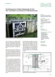
Planning of the ship lift at the Three - Krebs und Kiefer, Beratende ...
Planning of the ship lift at the Three - Krebs und Kiefer, Beratende ...
Planning of the ship lift at the Three - Krebs und Kiefer, Beratende ...

You also want an ePaper? Increase the reach of your titles
YUMPU automatically turns print PDFs into web optimized ePapers that Google loves.
uilt into <strong>the</strong> concrete construction over <strong>the</strong> entire <strong>lift</strong>ing height. Inside <strong>the</strong> nut post a spindle<br />
moves, revolving aro<strong>und</strong> its own axis. This spindle, for which <strong>the</strong> term rotary Archimedean screw<br />
is also used, is driven directly by <strong>the</strong> chamber drive system. Because <strong>of</strong> a direct mechanical cou-<br />
pling via a shaft system between <strong>the</strong> drives and <strong>the</strong> rotary Archimedean screws <strong>of</strong> <strong>the</strong> chamber<br />
safety mechanism, <strong>the</strong> rotary Archimedean screws always move synchronously with <strong>the</strong> drives<br />
in a force-free way. During normal oper<strong>at</strong>ions, <strong>the</strong>re is a certain amount <strong>of</strong> play between <strong>the</strong> ro-<br />
tary Archimedean screw and <strong>the</strong> nut post, so th<strong>at</strong> <strong>the</strong>y do not touch each o<strong>the</strong>r. The rotary Archi-<br />
medean screw is supported by articul<strong>at</strong>ed rods mounted on <strong>the</strong> upper and lower corner pieces <strong>of</strong><br />
<strong>the</strong> chamber (Figure 19). The upper corner piece is connected with <strong>the</strong> chamber by a pin con-<br />
struction and can be dismantled for repair work on <strong>the</strong> rotary Archimedean screw.<br />
If <strong>the</strong> pinion is overloaded, e.g. by a higher w<strong>at</strong>er level difference or by a loss <strong>of</strong> w<strong>at</strong>er, it deflects<br />
and escapes its load. In such a case, <strong>the</strong> chamber locks into <strong>the</strong> nut post via <strong>the</strong> rotary Archi-<br />
medean screw and is immedi<strong>at</strong>ely stopped.<br />
The nut post is installed over <strong>the</strong> entire height in sections ca. 5 m long. Because <strong>of</strong> <strong>the</strong> very high<br />
degree <strong>of</strong> accuracy required, it is not possible to build it into <strong>the</strong> first stage concrete. Cavities are<br />
<strong>the</strong>refore cre<strong>at</strong>ed in <strong>the</strong> first stage concrete in which steel girders can be embedded in a next<br />
step – after completion <strong>of</strong> <strong>the</strong> towers. The flanges <strong>of</strong> <strong>the</strong> steel girders have block connectors on<br />
<strong>the</strong> side towards <strong>the</strong> nut post and are flush with <strong>the</strong> second stage concrete. This measure con-<br />
siderably increases <strong>the</strong> level <strong>of</strong> accuracy. However, for <strong>the</strong> install<strong>at</strong>ion <strong>of</strong> <strong>the</strong> nut post, this step is<br />
not sufficient. In a final step, <strong>the</strong> nut post, which also has block connectors on its rear side, is<br />
adjusted. The block connectors now engage directly. The joint between <strong>the</strong> block connectors is<br />
designed to compens<strong>at</strong>e for a maximum <strong>of</strong> 2 cm. Following final exact adjustment, <strong>the</strong> joint is<br />
poured using high-strength low-shrinkage mortar. Vertical load transfer now takes place via <strong>the</strong><br />
block connectors. The tensile forces resulting from <strong>the</strong> eccentric load transfer are returned to <strong>the</strong><br />
concrete construction by means <strong>of</strong> screws and tendons.<br />
9 Ship chamber locking mechanism<br />
At its upper and lower holding points, <strong>the</strong> chamber is locked both vertically and horizontally. This<br />
ensures th<strong>at</strong> additional vertical loads, e.g. through a change in <strong>the</strong> w<strong>at</strong>er level, do not lead to<br />
additional loads on <strong>the</strong> driving pinion. Horizontal loads, e.g. from <strong>the</strong> impact <strong>of</strong> a <strong>ship</strong>, can easily<br />
be absorbed in <strong>the</strong> same way.<br />
Vertical locking takes place <strong>at</strong> <strong>the</strong> outermost point <strong>of</strong> each concrete shaft (Figures 14 and 20).<br />
Through a vertical cylinder, two horizontal pincers are positioned in two l<strong>at</strong>eral locking pockets<br />
loc<strong>at</strong>ed in <strong>the</strong> concrete. The pincers are <strong>the</strong>n extended horizontally and pre-tensioned vertically