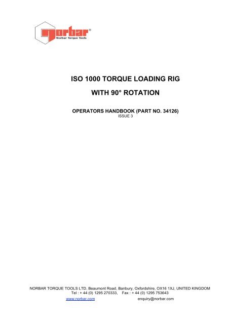
ISO 1000 TORQUE LOADING RIG WITH 90° ROTATION
ISO 1000 TORQUE LOADING RIG WITH 90° ROTATION - Tools Depot
ISO 1000 TORQUE LOADING RIG WITH 90° ROTATION - Tools Depot

Create successful ePaper yourself
Turn your PDF publications into a flip-book with our unique Google optimized e-Paper software.
<strong>ISO</strong> <strong>1000</strong> <strong>TORQUE</strong> <strong>LOADING</strong> <strong>RIG</strong><br />
<strong>WITH</strong> <strong>90°</strong> <strong>ROTATION</strong><br />
OPERATORS HANDBOOK (PART NO. 34126)<br />
ISSUE 3<br />
NORBAR <strong>TORQUE</strong> TOOLS LTD, Beaumont Road, Banbury, Oxfordshire, OX16 1XJ, UNITED KINGDOM<br />
Tel : + 44 (0) 1295 270333, Fax : + 44 (0) 1295 753643<br />
www.norbar.com<br />
enquiry@norbar.com
<strong>ISO</strong> <strong>1000</strong> OPERATORS HANDBOOK PAGE 1 OF 7<br />
ISSUE 3.0<br />
OCT 1997<br />
CONTENTS<br />
PAGE<br />
Introduction 2<br />
Specification 3<br />
Items Supplied 3<br />
Items Required 4<br />
Additional Options Available 4<br />
<strong>ISO</strong> <strong>1000</strong> with <strong>90°</strong> Rotation, Outlining Drawing (60118.OL) 5<br />
Machine Installation 6<br />
Horizontal to Vertical Operation 6<br />
Transducer and Instrument Installation 6<br />
Wrench Installation 7<br />
Items of Note 7
<strong>ISO</strong> <strong>1000</strong> OPERATORS HANDBOOK PAGE 2 OF 7<br />
ISSUE 3.0<br />
OCT 1997<br />
<strong>ISO</strong> <strong>1000</strong> <strong>TORQUE</strong> <strong>LOADING</strong> <strong>RIG</strong><br />
INTRODUCTION_____________________________________________________________<br />
The Norbar <strong>ISO</strong> <strong>1000</strong> torque loading rig with <strong>90°</strong> rotation is designed to test torque wrenches up to a<br />
maximum capacity of <strong>1000</strong> lbf.ft or 1350 N.m.<br />
Any wrench within the systems maximum capacity can be tested in both the horizontal and vertical<br />
planes, so allowing for a more accurate simulation of how the tool is actually used in the field.<br />
To measure the applied torque a torque transducer coupled to an appropriate measurement<br />
instrument are required.<br />
The loading rig can also be used to carry out torque tests on conventional spanners, wrenches and<br />
wrench extensions to their appropriate standard. With accessories the rig can also be used for<br />
checking tensiometer instruments for wire ropes and similar cables.<br />
Other <strong>ISO</strong> torque loading rigs available include:<br />
1. <strong>ISO</strong> 2000 N.m for testing at greater capacity. (Model No. 20502)<br />
2. Rate controlled <strong>ISO</strong> <strong>1000</strong> lbf.ft for applying torque at a set rate. (Model No. 60119)
<strong>ISO</strong> <strong>1000</strong> OPERATORS HANDBOOK PAGE 3 OF 7<br />
ISSUE 3.0<br />
OCT 1997<br />
<strong>ISO</strong> <strong>1000</strong> (<strong>90°</strong>) SPECIFICATION<br />
MIN OUTPUT <strong>TORQUE</strong><br />
MAX OUTPUT <strong>TORQUE</strong><br />
WRENCH ORIENTATION<br />
CALIBRATION DIRECTION<br />
1 Lbf.ft/1 N.m<br />
<strong>1000</strong> Lbf.ft/1350 N.m<br />
Vertical and Horizontal<br />
Clockwise and Anti-Clockwise<br />
DIMENSIONS (MAXIMUM) Width 1600 mm<br />
Height 610mm<br />
Depth 370mm<br />
WRENCH LENGTH Minimum 200mm<br />
Maximum 1350mm<br />
WEIGHT<br />
31.0 Kg<br />
GEAR TRAIN RATIO 1200:1<br />
SYSTEM OPERATING TEMPERATURE 0°C - 50°C<br />
ITEMS SUPPLIED ___________________________________________________________<br />
Part No.s<br />
1. <strong>ISO</strong> <strong>1000</strong> with 90 degree rotation. 60118<br />
2. Rotating lever with fixings. -<br />
3. Reaction post, clamp and wrench reset assembly. -<br />
4. Transducer collar large. 20583<br />
5. Transducer collar small 20584<br />
6. inch to 1/4 inch <strong>ISO</strong> adaptor. 20585<br />
7. inch to 3/8 inch <strong>ISO</strong> adaptor. 20586<br />
8. inch to 1/2 inch <strong>ISO</strong> adaptor. 20587<br />
9. inch to 3/4 inch insert adaptor. 29613<br />
10. Instruction Manual. 34086
<strong>ISO</strong> <strong>1000</strong> OPERATORS HANDBOOK PAGE 4 OF 7<br />
ISSUE 3.0<br />
OCT 1997<br />
ITEMS REQUIRED: __________________________________________________________<br />
1. Norbar torque transducer to suit capacity of test.<br />
2. Norbar Electronic Torque System instrument to display torque readings.<br />
For further information please contact Norbar Torque Tools or their distributor in your area.<br />
ADDITIONAL OPTIONS AVAILABLE____________________________________________<br />
20576 Reaction post for tensiometer testing.<br />
20502.38 7mm test cable for tensiometer testing.<br />
20502.39 6mm test cable for tensiometer testing.<br />
20502.40 5.3mm test cable for tensiometer testing.<br />
20502.41 5mm test cable for tensiometer testing.<br />
20502.43 4mm test cable for tensiometer testing.<br />
20502.43 3mm test cable for tensiometer testing.<br />
20502.44 2.5mm test cable for tensiometer testing.<br />
20502.45 1.6mm test cable for tensiometer testing.<br />
20552.1 9/32" test cable for tensiometer testing.<br />
20553.1 1/4" test cable for tensiometer testing.<br />
20554.1 7/32" test cable for tensiometer testing.<br />
20555.1 3/16" test cable for tensiometer testing.<br />
20556.1 5/32" test cable for tensiometer testing.<br />
20557.1 1/8" test cable for tensiometer testing.<br />
20558.1 3/32" test cable for tensiometer testing.<br />
20559.1 1/16" test cable for tensiometer testing.<br />
20580 6" quadrant for tensiometer testing (2.5-1.6 cable) (1/16" - 3/32")<br />
20581 9" quadrant for tensiometer testing (3-7mm cable) (1/6" - 9/32")<br />
20588 Small Reaction Plate for calibrating tools upto 20 N.m (i.e. SL0)<br />
NOTE:<br />
20588 can only be used on rigs ordered after 1 September 1995, without additional holes<br />
being drilled into box section. (See page 5).
<strong>ISO</strong> <strong>1000</strong> OPERATORS HANDBOOK PAGE 5 OF 7<br />
ISSUE 3.0<br />
OCT 1997
<strong>ISO</strong> <strong>1000</strong> OPERATORS HANDBOOK PAGE 6 OF 7<br />
ISSUE 3.0<br />
OCT 1997<br />
MACHINE INSTALLATION<br />
1. Locate the <strong>ISO</strong> machine on sturdy bench.<br />
2. Slide the rotating lever in from the back and secure with the 2 circlips provided (see drawing on<br />
page 5).<br />
3. Slide tool reaction post on to main beam.<br />
HORIZONTAL TO VERTICAL OPERATION<br />
1. The machine is shipped in the horizontal mounting position.<br />
To change to vertical position:<br />
2. Release the orientation release clamp by pushing it away to the extended position. (see drawing<br />
on page 5)<br />
3. Grip the rotating lever and gently pull to rotate the machine 90 degrees<br />
4. Reclamp the mechanism by pulling the orientation release clamp towards yourself.<br />
5. The rig is ready for vertical use.<br />
TRANSDUCER AND INSTRUMENT INSTALLATION<br />
1. Select the lowest capacity torque transducer to cover the wrench to be tested.<br />
2. Mount the male square of the transducer into the female square of the gear box, use adaptors<br />
to suit.<br />
3. The appropriate locating collar should be placed over the top of the transducer and locked by<br />
rotating through 90 degrees.<br />
4. Connect a transducer lead from the transducer to the instrument.<br />
5. Ensure the instrument functions correctly. (If in doubt see operators manual).
<strong>ISO</strong> <strong>1000</strong> OPERATORS HANDBOOK PAGE 7 OF 7<br />
ISSUE 3.0<br />
OCT 1997<br />
WRENCH INSTALLATION<br />
1. Slide the reaction post assembly to the far right of the reaction bar. This will allow the operator<br />
to index a ratchet wrench for insertion into the torque transducer.<br />
2. With the handle of the wrench running along the length of the rig, mount the torque wrench to<br />
be tested in the female square of the transducer.<br />
3. To adjust the reaction assembly slacken the clamp at the rear of the assembly. Move the post<br />
up and down to alter the height, and slide the assembly along the arm to adjust the lateral<br />
position.<br />
4. The ideal wrench orientation is horizontal with the bobbins reacting against the normal hand<br />
position, this is usually the centre of the wrench hand grip.<br />
NOTE:<br />
See drawing on page 5 for details.<br />
Wrench handle should be mounted under the wire strap for safe operation in horizontal or<br />
vertical operation.<br />
ITEMS OF NOTE<br />
1. The gear box makes movement in the output drive difficult to detect. Use the 'A' and 'B' arrows<br />
on the hand wheel and gearbox output as an indication.<br />
ie:- 'A' indicates direction to apply force.<br />
'B' indicates direction to release force.<br />
2. Always ensure the <strong>90°</strong> clamp is locked before loading the rig.<br />
3. In the case of a ratchet wrench, with push through square drives, it is important to ensure the<br />
square is operating on the correct side of the ratchet.<br />
4. When rotating the machine, ensure the transducer lead is not caught up in the mechanism.