TWL 1500 TORQUE WRENCH LOADER
TWL 1500 TORQUE WRENCH LOADER - Tools Depot
TWL 1500 TORQUE WRENCH LOADER - Tools Depot

Create successful ePaper yourself
Turn your PDF publications into a flip-book with our unique Google optimized e-Paper software.
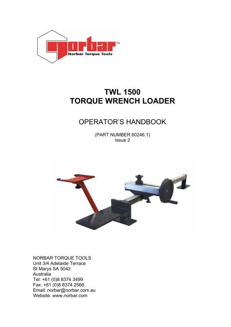
<strong>TWL</strong> <strong>1500</strong><br />
<strong>TORQUE</strong> <strong>WRENCH</strong> <strong>LOADER</strong><br />
OPERATOR’S HANDBOOK<br />
(PART NUMBER 60246.1)<br />
Issue 2<br />
NORBAR <strong>TORQUE</strong> TOOLS<br />
Unit 3/4 Adelaide Terrace<br />
St Marys SA 5042<br />
Australia<br />
Tel: +61 (0)8 8374 3499<br />
Fax: +61 (0)8 8374 2566<br />
Email: norbar@norbar.com.au<br />
Website: www.norbar.com
CONTENTS<br />
PAGE 1 OF 8<br />
Issue 2<br />
JANUARY 2005<br />
INTRODUCTION 2<br />
SPECIFICATION 3<br />
ITEMS SUPPLIED 3<br />
AVAILABLE OPTIONS 3<br />
ASSEMBLY INSTRUCTIONS<br />
A. ASSEMBLY OF TRANSDUCER PLATE TO STAND 4<br />
B. ASSEMBLY OF LOADING DEVICE TO STAND 4<br />
C. ASSEMBLY OF THE DISPLAY STAND 5<br />
D. ASSEMBLY OF FLANGE MOUNTED TRANSDUCERS 5<br />
TO TRANSDUCER PLATE<br />
E. ASSEMBLY OF PRO-TEST TRANSDUCER 6<br />
F. ASSEMBLY OF “SMART” <strong>TORQUE</strong> BLOCK TRANSDUCER 7<br />
OPERATING INSTRUCTIONS<br />
MACHINE INSTALLATION 8<br />
IMPORTANT NOTES 8<br />
<strong>WRENCH</strong> INSTALLATION 8<br />
PAGE
PAGE 2 OF 8<br />
Issue 2<br />
JANUARY 2005<br />
INTRODUCTION<br />
This handbook covers Torque Wrench Loader <strong>TWL</strong> <strong>1500</strong> (Part No. 60246).<br />
The Norbar <strong>TWL</strong><strong>1500</strong> Torque Wrench Loader is designed to test torque wrenches up<br />
to a maximum capacity of <strong>1500</strong> N.m.<br />
Any torque wrench within the systems maximum capacity can be tested in the<br />
horizontal plane to their appropriate standard.<br />
To measure the applied torque a torque transducer coupled to an appropriate display<br />
instrument are required.<br />
The <strong>TWL</strong><strong>1500</strong> can be equipped with a:-<br />
- Selection of 5 Flange Mounted Transducers from 10 Nm to <strong>1500</strong> N.m Capacity.<br />
(Part No’s. 50672.LOG to 50676.LOG)<br />
- Pro-Test Transducer of 400 N.m Capacity. (Part No. 43181)<br />
- Pro-Test Transducer of <strong>1500</strong> N.m Capacity. (Part No. 43189)<br />
-“SMART” Torque Block Transducer of 1000 N.m Capacity. (Part No.50683.LOG)
SPECIFICATION<br />
PAGE 3 OF 8<br />
Issue 2<br />
JANUARY 2005<br />
MIN OUTPUT <strong>TORQUE</strong>- 1 N.m<br />
MAX OUTPUT <strong>TORQUE</strong>- <strong>1500</strong> N.m<br />
<strong>WRENCH</strong> ORIENTATION-<br />
CALIBRATION DIRECTION -<br />
DIMENSIONS<br />
WEIGHT<br />
Horizontal<br />
Clockwise and Anti-Clockwise<br />
Width 730 mm<br />
Length 1720 mm<br />
Height 345 mm<br />
32 kg (70.5 lb)<br />
ITEMS SUPPLIED<br />
STAND<br />
FRAME ASSEMBLY BOLT KIT<br />
TRANSDUCER PLATE<br />
LOADING DEVICE ASSEMBLY<br />
DISPLAY STAND<br />
DISPLAY STAND BASE<br />
DISPLAY SUPPORT ARM<br />
DISPLAY STAND BOLT KIT<br />
FLANGE MOUNTED TRANSDUCER SPACERS (2 OFF)<br />
FLANGE MOUNTED TRANSDUCER BOLT KIT<br />
PRO-TEST ADAPTOR PLATE<br />
“SMART” <strong>TORQUE</strong> BLOCK BOLT KIT<br />
AVAILABLE OPTIONS<br />
i. Norbar Torque Tool Tester display instrument (part no.43215) and Flange<br />
Mounted Transducers (part no’s. 50672.LOG to 50676.LOG)<br />
ii. Norbar Torque Tool Tester display instrument (part no.43215) and STB1000<br />
“SMART” Torque Block .(part no.50683.LOG)<br />
iii. 400 Pro-Test transducer (part no. 43181) and display (part no. 43184)<br />
iv. <strong>1500</strong>ER Pro-Test transducer (part no. 43189) and display (part no.43184)
PAGE 4 OF 8<br />
Issue 2<br />
JANUARY 2005<br />
ASSEMBLY INSTRUCTIONS<br />
A. ASSEMBLY OF TRANSDUCER PLATE TO STAND<br />
1) Align flanges of transducer plate and use the frame assembly bolt kit (M10 bolts,<br />
washers and nuts) to fasten.<br />
2) Tighten bolts to 20 N.m.<br />
TRANSDUCER<br />
PLATE<br />
STAND<br />
B. ASSEMBLY OF LOADING DEVICE TO STAND<br />
1) Remove the 2 thumb screws and the clamp plate from the loading device.<br />
2) Position the loading device onto the stand ensuring that the hand wheel is on the<br />
side of the operator<br />
3) Reconnect the clamp plate using the 2 thumb screws and tighten in the desired<br />
position along the stand.<br />
4) Screw the handle to the hand wheel and tighten the locknut<br />
5) Slide the support bobbin onto the reaction post<br />
SUPPORT<br />
BOBBIN<br />
HAND WHEEL<br />
HANDLE<br />
THUMB<br />
SCREWS<br />
CLAMP PLATE<br />
LOADING DEVICE
PAGE 5 OF 8<br />
Issue 2<br />
JANUARY 2005<br />
C. ASSEMBLY OF THE DISPLAY STAND<br />
1) Screw the display stand to the display stand base using 2 off M5x16mm long<br />
screws.<br />
2) Insert the display stand base into the display support arm and tighten using the<br />
thumb nut from the display stand bolt kit.<br />
3) Attach the support arm to the transducer plate and fasten using the M10x50mm<br />
long screw and thumb nut from the display stand bolt kit.<br />
M5<br />
SCREWS<br />
DISPLAY<br />
STAND<br />
M10<br />
SCREW<br />
DISPLAY<br />
STAND<br />
BASE<br />
DISPLAY<br />
SUPPORT<br />
ARM<br />
THUMB<br />
NUTS<br />
D. ASSEMBLY OF FLANGE MOUNTED TRANSDUCERS TO TRANSDUCER<br />
PLATE.<br />
1) Place the spacers for the smaller transducers in the position shown below.<br />
2) Attach the transducers to the transducer plate in the positions shown below using<br />
the bolts supplied in the flange mounted transducer bolt kit. Tighten the<br />
M5x75 bolts to 5Nm, the M8x60 bolts to 10Nm and the M12x30 bolts to 15Nm.<br />
3) Ensure that the cables are extending out to the display stand side of the unit.<br />
4) Connect the transducer lead to the Torque Tool Tester display instrument and<br />
mount it on the display stand. Connect the power supply to the Torque Tool<br />
Tester.<br />
FMT10<br />
FMT<strong>1500</strong><br />
FMT25<br />
SPACERS<br />
FMT150<br />
FMT400
PAGE 6 OF 8<br />
Issue 2<br />
JANUARY 2005<br />
E. ASSEMBLY OF PRO-TEST TRANSDUCER<br />
1) Place the Pro-Test adaptor plate in the position shown below.<br />
2) Fasten the Pro-Test adaptor plate to the transducer plate using the 3 off<br />
M12x30mm long bolts from the flange mounted transducer bolt kit.<br />
Tighten to 15 N.m.<br />
3) Fasten the Pro-Test Transducer to the adaptor plate in one of the two mounting<br />
positions using the shoulder bolts provided with the Pro-Test.<br />
IMPORTANT ! Bolts must be Torque Tightened to 50 N.m. and replaced<br />
when removed. Refer to Pro-Test Operator’s Handbook.<br />
4) It is recommended that the Pro Test <strong>1500</strong>ER Transducer be fastened to the<br />
furthermost position from the loading device. The Pro-Test 400 Transducer is to<br />
be fastened to the closest position to the loading device.<br />
5) Mount the Pro-Test Display unit on top of the Pro-Test and connect to the<br />
transducer.<br />
6) Connect the power supply to the Pro-Test unit<br />
M12 BOLT<br />
PRO-TEST<br />
ADAPTOR<br />
PLATE<br />
TRANSDUCER<br />
PLATE<br />
M12 BOLT
PAGE 7 OF 8<br />
Issue 2<br />
JANUARY 2005<br />
F. ASSEMBLY OF “SMART” <strong>TORQUE</strong> BLOCK TRANSDUCER<br />
1) Attach the “SMART” Torque Block directly to the transducer plate using the 4 off<br />
M8x25mm long bolts from the “SMART” Torque Block bolt kit. There are two<br />
mounting positions to choose from on the transducer plate shown below.<br />
2) It is recommended that the “SMART” Torque Block be mounted in the furthermost<br />
position from the loading device, unless it is deemed necessary to mount it closer<br />
to the loading device due to the length of the torque wrench being tested.<br />
3) Tighten bolts to 42Nm.<br />
4) Connect the “Smart” Torque Block transducer lead to the Torque Tool Tester<br />
display instrument and mount it on the display stand.<br />
5) Connect the power supply to the Torque Tool Tester.<br />
ALTERNATE<br />
MOUNTING<br />
POSITIONS
PAGE 8 OF 8<br />
Issue 2<br />
JANUARY 2005<br />
OPERATING INSTRUCTIONS<br />
MACHINE INSTALLATION<br />
Secure the <strong>TWL</strong> <strong>1500</strong> onto a sturdy bench making sure there is enough room<br />
around the unit for the display stand and for the loading device to move freely along<br />
the length of the stand.<br />
IMPORTANT NOTES<br />
a. Ensure that the bolts fastening the transducer plate to the stand are torque<br />
tightened to 20 N.m.<br />
b. Always ensure loading device is firmly clamped before loading the rig.<br />
c. Always ensure the transducer leads are not caught up in the mechanism.<br />
d. To ensure trouble free use, periodically check that the screw thread and guide<br />
rails on the loading device are lubricated with a good quality machine oil.<br />
<strong>WRENCH</strong> INSTALLATION<br />
1. Slide the loading device assembly along the reaction bar far enough to allow<br />
clearance for the torque wrench to be installed in the <strong>TWL</strong><strong>1500</strong>.<br />
2. Select the lowest capacity torque transducer to cover the wrench to be tested.<br />
3. With the handle of the wrench running along the length of the reaction bar, mount<br />
the torque wrench to be tested in the female square drive of the selected torque<br />
transducer.<br />
4. Slide the loading device assembly along the reaction bar so that the support bobbin<br />
is reacting against the normal hand position of the wrench. This is usually the<br />
centre of the wrench hand grip.<br />
5. If the wrench is fitted with a square drive ratchet ensure that the orientation of the<br />
square drive allows maximum travel of the wrench handle by the support bobbin.<br />
6. Orientate the support bobbin so that the wrench maintains a horizontal position<br />
during testing.<br />
7. Firmly tighten the clamp plate of the loading device before loading the rig.<br />
8. Turn the hand-wheel smoothly to apply load to the torque wrench.<br />
9. Follow the appropriate calibration procedures for the torque wrench being tested.<br />
NOTE: In the case of a ratchet wrench with push through square drives, it is<br />
important to ensure the square is operating on the correct side of the<br />
ratchet.