Feed-forward in position-velocity loops
Feed-forward in position-velocity loops
Feed-forward in position-velocity loops

You also want an ePaper? Increase the reach of your titles
YUMPU automatically turns print PDFs into web optimized ePapers that Google loves.
Analog PI Velocity Loop<br />
October, 2000<br />
This column beg<strong>in</strong>s a two-part series on analog <strong>velocity</strong> <strong>loops</strong>. This month we will cover<br />
the PI controller.<br />
Theory<br />
Today, most discussion about motion control focuses on digital controls. That’s because<br />
digital control is new to many people so that there is more need for discussion. However,<br />
many applications still use analog servo <strong>loops</strong>. The differences between analog control<br />
and digital control are modest. The ma<strong>in</strong> differences are that analog controls do not have<br />
to deal with sampl<strong>in</strong>g, the process of runn<strong>in</strong>g servo calculations at fixed <strong>in</strong>tervals of time.<br />
Not hav<strong>in</strong>g to sample removes delay, allow<strong>in</strong>g analog controllers to be more responsive<br />
than their digital counterparts. Of course, analog controllers can be more difficult to<br />
adjust because servo ga<strong>in</strong>s are set with passive electrical components. Beyond that,<br />
digital and analog systems have a lot <strong>in</strong> common.<br />
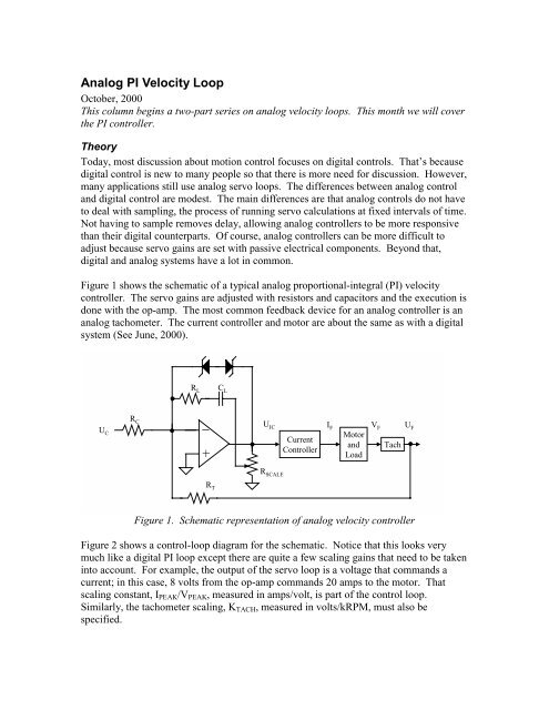
Figure 1 shows the schematic of a typical analog proportional-<strong>in</strong>tegral (PI) <strong>velocity</strong><br />
controller. The servo ga<strong>in</strong>s are adjusted with resistors and capacitors and the execution is<br />
done with the op-amp. The most common feedback device for an analog controller is an<br />
analog tachometer. The current controller and motor are about the same as with a digital<br />
system (See June, 2000).<br />
U C<br />
R C<br />
R L<br />
_<br />
+<br />
R T<br />
C L<br />
U IC I F V F U F<br />
R SCALE<br />
Current<br />
Controller<br />
Motor<br />
and<br />
Load<br />
Tach<br />
Figure 1. Schematic representation of analog <strong>velocity</strong> controller<br />
Figure 2 shows a control-loop diagram for the schematic. Notice that this looks very<br />
much like a digital PI loop except there are quite a few scal<strong>in</strong>g ga<strong>in</strong>s that need to be taken<br />
<strong>in</strong>to account. For example, the output of the servo loop is a voltage that commands a<br />
current; <strong>in</strong> this case, 8 volts from the op-amp commands 20 amps to the motor. That<br />
scal<strong>in</strong>g constant, IPEAK/VPEAK, measured <strong>in</strong> amps/volt, is part of the control loop.<br />
Similarly, the tachometer scal<strong>in</strong>g, KTACH, measured <strong>in</strong> volts/kRPM, must also be<br />
specified.
U C<br />
1<br />
R C<br />
+<br />
_<br />
I E<br />
1<br />
sC L<br />
R L<br />
+<br />
+<br />
1<br />
R T<br />
R SCALE<br />
U F<br />
U IC<br />
I PEAK<br />
V PEAK<br />
K TACH<br />
I C<br />
Current<br />
Loops<br />
Figure 2. Control-system block diagram<br />
The servo ga<strong>in</strong>s are set by a few resistors and a capacitor. RC scales the command and RT<br />
scales the tachometer feedback. RL is the key component <strong>in</strong> tun<strong>in</strong>g the proportional ga<strong>in</strong><br />
and CL is key <strong>in</strong> sett<strong>in</strong>g the <strong>in</strong>tegral ga<strong>in</strong>. The two zener diodes <strong>in</strong> Figure 1 are not shown<br />
<strong>in</strong> Figure 2. These diodes provide anti-w<strong>in</strong>dup, the feature where the ga<strong>in</strong> of the<br />
<strong>in</strong>tegrator is clamped dur<strong>in</strong>g large <strong>velocity</strong> sw<strong>in</strong>gs. Without anti-w<strong>in</strong>dup, the <strong>in</strong>tegrator<br />
can cont<strong>in</strong>ue <strong>in</strong>tegrat<strong>in</strong>g error with large <strong>velocity</strong> sw<strong>in</strong>gs; this can cause needlessly large<br />
overshoot.<br />
RSCALE is a potentiometer provided as an overall loop ga<strong>in</strong> adjustment. RSCALE is directly<br />
<strong>in</strong> l<strong>in</strong>e with the motor and load, KT/JT. JT represents the total (motor plus load) <strong>in</strong>ertia.<br />
When JT changes, it changes the loop ga<strong>in</strong> and that changes the performance of the<br />
system. With RSCALE, you can adjust this change out with<strong>in</strong> a reasonable range. Of<br />
course, you could make the same sort of adjustment by chang<strong>in</strong>g RL and CL, but that is<br />
less convenient because it can <strong>in</strong>volve solder<strong>in</strong>g <strong>in</strong> new components.<br />
Tun<strong>in</strong>g an analog PI controller is very much like tun<strong>in</strong>g a digital system. The key is to<br />
tune <strong>in</strong> zones (see June, 2000). With a PI controller, there are two zones: proportional<br />
and <strong>in</strong>tegral. To tune, apply a small-magnitude <strong>velocity</strong> step command to the drive. You<br />
should adjust the step to be as large as possible without call<strong>in</strong>g for peak current from the<br />
drive. If you ask for too much current, you will saturate the current <strong>loops</strong>; this makes the<br />
loop more difficult to tune correctly. Typical step commands are from 50 RPM to about<br />
500 RPM, depend<strong>in</strong>g on the loop speed and the amount of <strong>in</strong>ertia. Now, adjust the zones<br />
one at a time. First, zero the <strong>in</strong>tegral zone (short CL) and tune RL to get a little overshoot.<br />
Next, add <strong>in</strong> CL until the overshoot reaches about 15%. The response with these ga<strong>in</strong><br />
sett<strong>in</strong>gs are shown <strong>in</strong> Figure 3. Remember to set the RSCALE pot away from the ends of<br />
travel of travel. That way, if the <strong>in</strong>ertia varies up or down <strong>in</strong> the future, you can use<br />
RSCALE to adjust performance.<br />
I F<br />
K T<br />
J Ts<br />
V M
UC, command<br />
UF, tach feedback<br />
IF, motor current<br />
Zone 1: Short CL to create a proportional<br />
controller. Adjust RL to 500 kOhm to get<br />
maximum response without overshoot.<br />
Scal<strong>in</strong>g: UC and UF: 50 mV/div; this is<br />
equivalent to about 44 RPM for the scal<strong>in</strong>g<br />
of this system. IF: 20 Amps/div.<br />
UC, command<br />
UF, tach feedback<br />
IF, motor current<br />
Zone 2: Leave RL at 500 kOhm and adjust<br />
CL. Here, a sett<strong>in</strong>g of 10 uF yields the<br />
10%-15% overshoot to step that usually<br />
<strong>in</strong>dicates good response for a PI controller.<br />
Laboratory<br />
Want to tune an analog PI <strong>velocity</strong> controller yourself? Then log onto<br />
www.motionsystemdesign.com and download the most recent version of the ModelQ<br />
simulation program. Launch the program and select October’s model. Click “Run.”<br />
This is the analog PI controller discussed <strong>in</strong> this column. The command (blue) and<br />
response (black) are overlaid; the current is shown below; it’s a good idea to monitor<br />
current when tun<strong>in</strong>g to ensure that the system rema<strong>in</strong>s out of saturation. Remember, if<br />
you have questions about constants, click on the button “About this model….”<br />
To tune the system, first tune Zone 1. Set CL = 0 and adjust RL to where some overshoot<br />
starts to appear and then adjust it down. In this case, overshoot occurs at RL =<br />
600 kOhm, so adjust RL down to 500 kOhm to elim<strong>in</strong>ate the overshoot. Now add <strong>in</strong> CL.<br />
Always start with a fairly large value of CL. Remember that lower values of CL create<br />
larger servo ga<strong>in</strong>s. Here, a value of 10 uF gives a good step response for a PI controller:<br />
about 15% overshoot. Now, adjust the load <strong>in</strong>ertia down by a factor of two. Notice how<br />
this degrades the performance of the system by creat<strong>in</strong>g r<strong>in</strong>g<strong>in</strong>g. F<strong>in</strong>ally, adjust RSCALE<br />
down from 2 to 1 to account for the <strong>in</strong>ertia change. On the physical amplifier, this would<br />
be done by adjust<strong>in</strong>g the pot. Notice how performance is restored. This one of the key<br />
functions of RSCALE.