ELECTRICAL REQUIREMENTS AND PRECAUTIONS Your Caldera ® spa has been carefully designed to give you maximum safety against electrical shock. Connecting the spa to an improperly wired circuit will negate many of the spa’s safety features. Improper wiring may also cause electrocution, risk of fire, and other risks of injuries. Please read and follow the electrical installation requirements and instructions for your spa completely! 230 VOLT converted Cantabria The Utopia Cantabria requires an additional 20 amp breaker in order to operate the heater at the same time as the blower and all three jet pumps. CALDERA SPAS MUST BE WIRED IN ACCORDANCE WITH ALL APPLICABLE LOCAL ELECTRICAL CODES. ALL ELECTRICAL WORK SHOULD BE DONE BY AN EXPERIENCED LICENSED ELECTRICIAN. WE RECOMMEND THE USE OF APPROPRIATE ELECTRICAL CONDUIT, FITTINGS, AND WIRE FOR ALL CIRCUITS. An electrical subpanel containing two GFCI breakers is included with each spa. We recommend that this subpanel be used to supply power and protect the spa. This subpanel requires a 70 amp, single phase, 230 volt, four wire service (two line, one neutral, one ground). The ground wire must never be less than #10 AWG. Use NEC 250-122 (table) and local codes for more information. A minimum #6 AWG solid copper bond wire is also required. Mount the subpanel in the vicinity of the spa, but not within five feet, in accordance with local codes. INSTALLATION INSTRUCTIONS 1. 2. 3. 4. 5. ELECTRICAL INSTALLATION To connect the electrical service, first remove the screws from the equipment compartment door (remove the fiber optic light cover and remove fiber optic cable from door), lower the door one inch and remove the door. Locate the spa control box. Remove the screws on the front of the control box and remove the control box cover. Route the electrical service from the subpanel into the spa equipment compartment. NOTE: The subpanel must be placed in sight of the spa, no closer than five feet. Connect wire to bottom of control box using a minimum of c/v” liquid-tight, flex conduit fitting. Remove jumpers A from TB-1 WIRING CONNECTIONS 1. Identify the TB-1 terminal block, located inside the control box at the lower left-hand corner. 2. Connect the #12 AWG, BLUE wire, from the subpanel 20 amp breaker, terminal L1 to TB-1, terminal 1 3. Connect the #12 AWG, RED wire, from the subpanel 20 amp breaker, terminal L2 to TB-1, terminal 3 4. Connect the #12 AWG, BLUE wire, from the subpanel 20 amp breaker, terminal L1 to TB-1, terminal 2 5. Connect the #12 AWG, RED wire, from the subpanel 20 amp breaker, terminal L2 to TB-1, terminal 4 NOTE: The WHITE neutral wire must be attached to the LOAD neutral on the 230 volt, 30 amp breaker (not to the neutral bus bar in the subpanel). The WHITE neutral wire coming from the breaker itself is already connected to the neutral bus bar. 6. Connect the #10 AWG, BLUE wire, from the subpanel 30 amp breaker, terminal L1 to TB-1, terminal 5 7. Connect the #10 AWG, RED wire, from the subpanel 30 amp breaker, terminal L2 to TB-1, terminal 6 8. Connect the #10 AWG, WHITE wire, from the subpanel 30 amp breaker, terminal N (load neutral) to TB-1, terminal 7 9. Connect the #6 AWG, GREEN wire, from the subpanel GROUND bar to TB-1, system ground terminal. 10. Using the pressure wire connector provided on the outside of the control box, bond the spa to all exposed metal equipment or fixtures, handrails, and the concrete pad (if applicable) per N.E.C. and local codes. 11. Replace the control box cover and securely tighten the fastening screws. Close and secure the equipment compartment door as follows: a. Place top of door or panel directly below bartop against the frame of the spa. b. Push bottom of door or panel against the spa frame. c. Slide door or panel upward (pushing in on center of door) until screw holes line up. d. Slightly pull on door or panel, if door remains against the spa then replace the screws. WARNING: FILL THE SPA WITH WATER e. If the door does not lock into position, repeat the previous steps. BEFORE TURNING ON THE POWER! (See STARTUP AND REFILL PROCEDURES.) Once your spa has been filled with water, turn it on and test all of the circuit breakers. NOTE: If both breakers immediately trip, verify that the #10 AWG WHITE neutral wire is connected from TB-1 terminal 5 to the N (load neutral) terminal of the 30 amp subpanel breaker. Each breaker should be tested prior to each use. WARNING: Removing or bypassing any To test the breakers: GFCI breaker will result in an unsafe spa and 1. Push the “TEST” button on each GFCI breaker, and observe it click OFF. will void the spa’s warranty. 2. Wait 30 seconds, then push the breaker switch to the OFF (down) position (to ensure that it has completely disengaged), then push the breaker switch to the ON (up) position. If you don't wait 30 seconds, the spa’s control panel may flash four lines on and off – try again. If any of the GFCI breakers fails to operate in this manner, your spa may have an electrical malfunction, and you may be at risk of electrical shock. Turn off all circuits and do not use the spa until the problem has been corrected by an authorized service agent. SERVICE NOTE: All Caldera spas have diagnostic functions that are displayed on the control panel. Four flashing lines are visible on the control panel if the heater high limit thermostat has tripped. If the four flashing lines are visible, follow the instructions in the troubleshooting section to identify and correct the cause. The four flashing lines will stop flashing once the problem has been corrected. 14
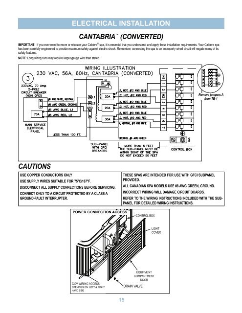
ELECTRICAL INSTALLATION CANTABRIA (converted) IMPORTANT: If you ever need to move or relocate your Caldera ® spa, it is essential that you understand and apply these installation requirements. Your Caldera spa has been carefully engineered to provide maximum safety against electric shock. Remember, connecting the spa to an improperly wired circuit will negate many of its safety features. NOTE: Long wiring runs may require larger-gauge wire than stated. Remove jumpers A from TB-1 CAUTIONS USE COPPER CONDUCTORS ONLY USE SUPPLY WIRES SUITABLE FOR 75°C/167°F. DISCONNECT ALL SUPPLY CONNECTIONS BEFORE SERVICING. CONNECT ONLY TO A CIRCUIT PROTECTED BY A CLASS A GROUND-FAULT INTERRUPTER. THESE SPAS ARE INTENDED FOR USE WITH GFCI SUBPANEL PROVIDED. ALL CANADIAN SPA MODELS USE #8 AWG GREEN, GROUND. INCORRECT WIRING WILL DAMAGE CIRCUIT BOARDS. REFER TO THE WIRING INSTRUCTIONS INCLUDED WITH THE SUB- PANEL FOR DETAILED WIRING INSTRUCTIONS. POWER CONNECTION ACCESS CONTROL BOX LIGHT COVER 230V WIRING ACCESS OPENINGS ON LEFT & RIGHT HAND SIDE DRAIN VALVE EQUIPMENT COMPARTMENT DOOR 15