View Presentation - EPC
View Presentation - EPC
View Presentation - EPC
- No tags were found...

You also want an ePaper? Increase the reach of your titles
YUMPU automatically turns print PDFs into web optimized ePapers that Google loves.
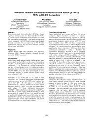
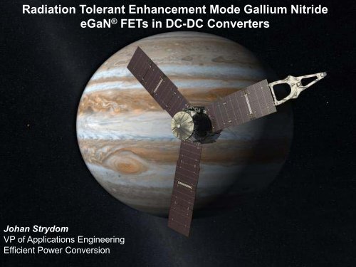
Radiation Tolerant Enhancement Mode Gallium Nitride<br />
eGaN ® FETs in DC-DC Converters<br />
Johan Strydom<br />
VP of Applications Engineering<br />
Efficient Power Conversion<br />
<strong>EPC</strong> - The Leader in eGaN ® FETs | March 2013 | GOMAC Tech www.epc-co.com 1
Agenda<br />
• Background<br />
• Radiation Tolerance<br />
• Forward Converter case study<br />
• Other DC-DC converters<br />
• Conclusions<br />
<strong>EPC</strong> - The Leader in eGaN ® FETs | March 2013 | GOMAC Tech www.epc-co.com 2
eGaN ® FET Structure<br />
AlGaN Electron Generating Layer<br />
Dielectric<br />
S<br />
G<br />
- - - - - - - - - - - - - - - - - - -<br />
D<br />
Two Dimensional<br />
Electron Gas (2DEG)<br />
GaN<br />
Aluminum Nitride<br />
Isolation Layer<br />
Si<br />
<strong>EPC</strong> - The Leader in eGaN ® FETs | March 2013 | GOMAC Tech www.epc-co.com 3
Parameter Comparison<br />
Parameter Si MOSFET GaN Comment<br />
V GS(MAX) ±20 V +6 V/ -5 V<br />
V SD / body diode 1 V 1.5 V – 2.5 V<br />
V GS(TH) 2 V – 4 V 0.7 V to 2.5 V Logic- level<br />
device<br />
R G ≥1 Ω 0.5 Ω- 0.8 Ω<br />
R DS(ON) change over<br />
temp<br />
V GS(TH)<br />
change over temp.<br />
Q RR (rev. recovery<br />
charge)<br />
+70 % +60 % 25ºC to 125ºC<br />
-33 % -3 % ~ No temp.<br />
dependence<br />
High 0 Schottky / SiC<br />
performance<br />
For 100V devices<br />
<strong>EPC</strong> - The Leader in eGaN ® FETs | March 2013 | GOMAC Tech www.epc-co.com 4
Device Figure of Merit<br />
• Devices of different sizes / technologies can be<br />
compared using a Figure of Merit.<br />
• For given technology, R DS(ON) x Q = ~ Constant<br />
• Some typical FoMs:<br />
• Synchronous rectifier (SR) performance α R DS(ON) x Q G<br />
• Switching performance α R DS(ON) x Q GD<br />
<strong>EPC</strong> - The Leader in eGaN ® FETs | March 2013 | GOMAC Tech www.epc-co.com 5
Device Figures of Merit<br />
~20x - 40x Improvement<br />
SR FoM<br />
Switching FoM<br />
IRF Rad Hard (R DS(ON) ⋅Q G ) IRF Rad Hard (R DS(ON) ⋅Q GD )<br />
eGaN FET (R DS(ON) ⋅Q G ) eGaN FET (R DS(ON) ⋅Q GD )<br />
<strong>EPC</strong> - The Leader in eGaN ® FETs | March 2013 | GOMAC Tech www.epc-co.com 6
Silicon vs. GaN Comparison<br />
100 V Commercial<br />
MOSFETS<br />
100 V Rad Hard<br />
MOSFETs<br />
Lower is better<br />
100 V eGaN FETs<br />
<strong>EPC</strong> - The Leader in eGaN ® FETs | March 2013 | GOMAC Tech www.epc-co.com 7
Radiation Testing Results<br />
<strong>EPC</strong> - The Leader in eGaN ® FETs | March 2013 | GOMAC Tech www.epc-co.com 8
SEE Radiation Performance<br />
Voltage<br />
250<br />
200<br />
150<br />
100<br />
SEE Heavy Ion Testing - Au<br />
Fail<br />
Out of Spec<br />
Undamaged<br />
87.2 MeV LET with<br />
up to 190 V bias<br />
50<br />
0<br />
200 V Gen 1 FETs 200 V Gen 2 FETs<br />
MIL-STD-750E, METHOD 1080<br />
<strong>EPC</strong> - The Leader in eGaN ® FETs | March 2013 | GOMAC Tech www.epc-co.com 9
Total Dose Results – 100 V<br />
<strong>EPC</strong>1001 Gate and Drain-Source Leakage Current<br />
Leakage Current (micro Amperes)<br />
1000<br />
100<br />
10<br />
1<br />
0.E+00 5.E+05 1.E+06<br />
Radiation Dose<br />
Data up to 1 MRad<br />
MIL-STD-750E, METHOD 1019<br />
Threshold Voltage (V)<br />
IGSS after VGS<br />
IDSS after VGS<br />
IGSS after VGS<br />
IDSS after VGS<br />
IGSS after VDS<br />
IDSS after VDS<br />
IGSS after VDS<br />
IDSS after VDS<br />
2.500<br />
2.300<br />
2.100<br />
1.900<br />
1.700<br />
1.500<br />
1.300<br />
1.100<br />
.900<br />
.700<br />
<strong>EPC</strong>1001 Threshold Voltage<br />
VTH after VGS<br />
VTH after VGS<br />
VTH after VDS<br />
VTH after VDS<br />
0.E+00 5.E+05 1.E+06<br />
Radiation Dose<br />
<strong>EPC</strong> - The Leader in eGaN ® FETs | March 2013 20112 | | GOMAC Tech<br />
www.epc-co.com<br />
10
RH Packaging<br />
<strong>EPC</strong> - The Leader in eGaN ® FETs | March 2013 | GOMAC Tech www.epc-co.com 11
Package/ Drive Considerations<br />
Gate<br />
Return<br />
Kelvin Source<br />
contact<br />
V dd<br />
Gate<br />
Drain<br />
V gate<br />
Load<br />
I g(on)<br />
Drain<br />
Source<br />
Gate<br />
In<br />
Q sw<br />
I d<br />
Gate<br />
Return<br />
Source<br />
C bypass<br />
I g(off)<br />
(bottom view)<br />
Driver<br />
Power Source contact<br />
• 4 - Pad package separate drive loop from power loop.<br />
• Separate Kelvin gate return minimizes common source<br />
inductance.<br />
<strong>EPC</strong> - The Leader in eGaN ® FETs | March 2013 | GOMAC Tech www.epc-co.com 12
1 st Gen RH GaN Product line<br />
PART NO. VOLTAGE CURRENT PEAK R DS(ON) (mΩ) Q G (nC)<br />
FOM<br />
Q G * R DS(ON)<br />
MGN2915U4A 40 V 33 A 150 A 4 11.6 46.4<br />
MGN2914U4A 40 V 10 A 40 A 16 3 48<br />
MGN2905U4A 60 V 25 A 100 A 7 10 70<br />
MGN2909U4A 60 V 6 A 25 A 30 2.4 72<br />
MGN2901U4A 100 V 25 A 100 A 7 10.5 73.5<br />
MGN2907U4A 100 V 6 A 25 A 30 2.7 81<br />
MGN2911U4A 150 V 12 A 40 A 25 6.7 167.5<br />
MGN2913U4A 150 V 3 A 12 A 100 1.7 170<br />
MGN2910U4A 200 V 12 A 40 A 25 7.5 187.5<br />
MGN2912U4A 200 V 3 A 12 A 100 1.9 190<br />
(Preliminary)<br />
U4A<br />
U4A<br />
<strong>EPC</strong> - The Leader in eGaN ® FETs | March 2013 | GOMAC Tech www.epc-co.com 13
Forward Converter<br />
<strong>EPC</strong> - The Leader in eGaN ® FETs | March 2013 | GOMAC Tech www.epc-co.com 14
Forward Converter Case-Study<br />
50 W / 225 kHz<br />
Outputs in series allow<br />
up to 2 A / 40 W output<br />
RH 200 V, 60 mΩ MOSFET<br />
Replace with<br />
RH 200 V, 25 mΩ eGaN FET<br />
<strong>EPC</strong> - The Leader in eGaN ® FETs | March 2013 | GOMAC Tech www.epc-co.com 15
Device Comparison<br />
GaN<br />
Silicon<br />
Si MOSFET<br />
RH eGaN FET<br />
<strong>EPC</strong> - The Leader in eGaN ® FETs | March 2013 | GOMAC Tech www.epc-co.com 16
Experimental Setup<br />
Drain Connection<br />
Source<br />
Connection<br />
Gate Connection<br />
<strong>EPC</strong> - The Leader in eGaN ® FETs | March 2013 | GOMAC Tech www.epc-co.com 17
Efficiency Results<br />
2.5 % – 5 % improvement in Efficiency<br />
<strong>EPC</strong> - The Leader in eGaN ® FETs | March 2013 | GOMAC Tech www.epc-co.com 18
Estimated Device Losses<br />
60 % Loss Reduction<br />
<strong>EPC</strong> - The Leader in eGaN ® FETs | March 2013 | GOMAC Tech www.epc-co.com 19
Device Loss Comparison<br />
Improvement in BOTH conduction and switching losses<br />
<strong>EPC</strong> - The Leader in eGaN ® FETs | March 2013 | GOMAC Tech www.epc-co.com 20
Other DC-DC converters<br />
<strong>EPC</strong> - The Leader in eGaN ® FETs | March 2013 | GOMAC Tech www.epc-co.com 21
Synchronous Buck POL<br />
Replacing Silicon with GaN<br />
MGN2915U4A<br />
• eGaN FET allows increased switching frequency<br />
• Reduced size / weight of passive components<br />
<strong>EPC</strong> - The Leader in eGaN ® FETs | March 2013 | GOMAC Tech www.epc-co.com 22
GaN vs. Silicon<br />
Nearly a 10:1 improvement in power dissipated<br />
Power Loss (W)<br />
14<br />
12<br />
10<br />
8<br />
6<br />
4<br />
2<br />
GaN- MGN2015<br />
IRHMS57Z60<br />
0<br />
100 200 300 400 500 600 700 800 900 1000<br />
Frequency (kHz)<br />
• Irms= 2A, Vcc= 24Vdc, Duty= 50%, Rds(on)= .0045 ohms<br />
• Power MOSFET losses can be prohibitive @ 500KHz<br />
• eGaN FET power loss @ 500kHz < Power MOSFET @ 100kHz!<br />
<strong>EPC</strong> - The Leader in eGaN ® FETs | March 2013 | GOMAC Tech www.epc-co.com 23
Low voltage POL<br />
12 V IN<br />
3.3 V OUT<br />
10 A OUT<br />
100kHz<br />
• Highest loss: MOSFETs and Inductor<br />
<strong>EPC</strong> - The Leader in eGaN ® FETs | March 2013 | GOMAC Tech www.epc-co.com 24
POL Efficiency Comparison<br />
95%<br />
eGaN FETs = 92.5%, 500kHz<br />
90%<br />
12 V IN<br />
Efficiency<br />
85%<br />
80%<br />
75%<br />
70%<br />
65%<br />
60%<br />
55%<br />
50%<br />
45%<br />
Rad Hard MOSFETs = 84%, 100kHz<br />
0 2 4 6 8 10 12<br />
Output Current<br />
eGaN 1.5 V<br />
eGaN 2.5 V<br />
eGaN 3.3 V<br />
IR 1.8 V<br />
IR 2.5 V<br />
IR 3.3 V<br />
<strong>EPC</strong> - The Leader in eGaN ® FETs | March 2013 | GOMAC Tech www.epc-co.com 25
Conclusions<br />
• eGaN FETs have exceptional Heavy Ion hardness and<br />
TID capability beyond 1MRad<br />
• RH eGaN FETs offer at least 3x improvement in device<br />
losses.<br />
• This improvement allows increased switching frequency<br />
and efficiency while reducing overall size and weight.<br />
• eGaN FETs allow RH DC-DC to be on par with current<br />
commercial power supplies.<br />
<strong>EPC</strong> - The Leader in eGaN ® FETs | March 2013 | GOMAC Tech www.epc-co.com 26
The end of the<br />
road for silicon…..<br />
is the beginning of<br />
the eGaN FET<br />
journey!<br />
<strong>EPC</strong> - The Leader in eGaN ® FETs | March 2013 | GOMAC Tech www.epc-co.com 27