Cirrus Aircraft Update Webinar
SR22T - Cirrus Design Authorized Service Center Home
SR22T - Cirrus Design Authorized Service Center Home
- No tags were found...

You also want an ePaper? Increase the reach of your titles
YUMPU automatically turns print PDFs into web optimized ePapers that Google loves.
<strong>Cirrus</strong> <strong>Aircraft</strong> <strong>Update</strong> <strong>Webinar</strong><br />
Authorized Service Centers – 6/23/2010
Announcements:<br />
1. SR22T<br />
2. LANDING GEAR SIMULATOR<br />
3. AIR CONDITIONING<br />
PROMOTION<br />
4. CIRRUS CERTIFIED<br />
PROMOTION
OTHER KEY PERFORMANCE DIFFERENTIATORS FOR SR22T<br />
GREATER CABIN HEAT<br />
QUIETER TAKEOFF & CLIMB<br />
NOISE<br />
GREATER USEFUL LO<br />
IMPROVED DECELERATION<br />
VIA “BRAKING” EFFECT OF<br />
PROP<br />
IMPROVED TAKEOFF & CLIMB<br />
PERFORMANCE
KEY DESIGN DIFFERENTIATORS FOR<br />
SR22T<br />
50‐K K ENGINE THAT WE PARTNERED WITH TCM TO DEVELOP SPECIFICALLY FOR<br />
SR22T. THIS IS A NEW ENGINE MODEL.
KEY DESIGN DIFFERENTIATORS FOR<br />
SR22T<br />
TSIO‐550<br />
550‐K K ENGINE<br />
MODIFIED NLG – OLEO STRUT
KEY DESIGN DIFFERENTIATORS FOR<br />
SR22T<br />
TSIO‐550<br />
550‐K K ENGINE<br />
MODIFIED COWL<br />
MODIFIED NLG – OLEO STRUT
KEY DESIGN DIFFERENTIATORS FOR<br />
SR22T<br />
TSIO‐550<br />
550‐K K ENGINE<br />
MODIFIED ECS CONTROLLER<br />
MODIFIED COWL<br />
MODIFIED NLG – OLEO STRUT
SR22T
SR22T<br />
This document is for training purposes only; Always<br />
consult <strong>Cirrus</strong> <strong>Aircraft</strong> and Teledyne Continental Motors<br />
Technical Publications before performing maintenance<br />
on all <strong>Cirrus</strong> aircraft.
SR22T<br />
OVERVIEW<br />
•TCM TSIO550K twin turbocharged 315 HP engine.<br />
•New nose landing gear utilizes oleo strut for shock absorbsion.<br />
•Changes in environmental system architecture.<br />
•New Hartzel prop governor.<br />
•Airframe structural changes including new cowl design.<br />
•Added inspection and maintenance items
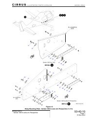
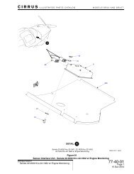
Nose Landing gear<br />
Operation description;<br />
SR22T<br />
Shock absorption in weight on wheels attitude is accomplished by a nitrogen-oleo strut installed between the<br />
hinged members of the nose landing gear strut and the undercarriage of the engine mount. Regular<br />
inspection, servicing and maintenance standards are critical in preventing injury to occupants and significant<br />
damage to prop, engine and airframe.
Nose Landing Gear<br />
SR22T<br />
Inspection/Check (AMM 32-20) performed every 50<br />
hour inspection;<br />
Remove engine cowling and NLG faring.<br />
Using flashlight and 10X magnifier, visually inspect<br />
fillet weld on bottom of strut for cracks, deformation<br />
or other signs of distress.<br />
Inspect oleo strut for security, cracks, corrosion and<br />
cleanliness.<br />
Ensure spherical bearings at oleo attach points are<br />
fully captured.<br />
At room temperature with aircraft at nominal weight,<br />
apply rocking force to nose of aircraft. Allow aircraft<br />
to stabilize.<br />
Verify exposed rod (chrome) of oleo is 2.0-2.25<br />
inches. If exposed piston rod is below tolerance,<br />
strut requires servicing per AMM 12-10.
Nose Landing Gear<br />
SR22T<br />
Adjustment/Test (AMM 32-20) performed every 100 hour and<br />
annual inspection;<br />
Remove engine cowling and raise nose of aircraft per AMM<br />
07-10.<br />
Solvent clean oleo and perform visual inspection of oleo fill<br />
valve and piston rod surface.<br />
If leakage is evident at fill valve, replace fill valve or seal per<br />
AMM 32-20. If piston rod shows signs of minor corrosion or<br />
scoring, repair per AMM 32-20. If corrosion or scoring is<br />
excessive or cannot be removed, replace oleo strut per AMM<br />
32-20.<br />
If piston rod shows signs of leakage identified by streamlets of<br />
fluid (the rod maintains a light film of hydraulic fluid for<br />
lubrication), replace oleo strut per AMM 32-20.<br />
If hydraulic fluid or nitrogen charge is suspected insufficient,<br />
perform strut servicing per AMM 12-10
Nose Landing Gear<br />
Servicing AMM12-10;<br />
SR22T<br />
Remove engine cowl and raise nose of aircraft per AMM 07-10.<br />
Remove cap from filler valve and slowly open fill valve, allowing<br />
one minute for strut to de-pressurize.<br />
If replenishing nitrogen only, close fill valve.<br />
Fluid servicing; attach length of clear 5/16” hose to fill valve and<br />
place other end in a graduated cylinder containing a minimum .5<br />
quarts mil spec 5606 hydraulic fluid. Slowly raise strut verifying<br />
gas and fluid expel from strut Slowly lower strut verifying fluid is<br />
being drawn into strut. Repeat raising and lowering until all<br />
entrapped air is eliminated and strut expels steady stream of fluid<br />
for at least ½ of compression. Raise strut and hold while closing<br />
fill valve and remove hose..<br />
Nitrogen servicing; connect high pressure hose from nitrogen tank<br />
to fill valve. Slowly pressurize nitrogen hose to 20 psi. Slowly open<br />
fill valve allowing strut to reach full extension. At a rate of no more<br />
than 100 psi/minute, pressurize strut to 350.0±10.0 psi. Close fill<br />
valve and torque to 45-70 in-lb. Close nitrogen tank valve and<br />
relieve pressure in nitrogen hose. Disconnect hose and install fill<br />
valve cap.<br />
Replace strut rubber seal components every 2000 hrs.
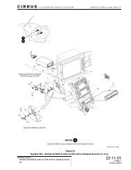
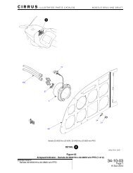
Environmental Systems<br />
SR22T<br />
Operation description;<br />
As in SR22 2439 & subs, fresh air enters the cabin through<br />
a NACA vent located on the lower right cowl and is ducted to<br />
the mixing chamber mounted to the forward firewall.<br />
Cabin heat is obtained by taking turbocharged “Bleed air”<br />
from the left and right turbocharger intercoolers located in<br />
the engine baffling. The intercooler bleed air is ducted into a<br />
heat exchanger surrounding the turbine waste gate<br />
crossover pipe. The hot air is then ducted to the mixing<br />
chamber and is mixed with fresh air to crew selected comfort<br />
settings. Excess hot air is “dumped overboard” by a flapper<br />
valve located on the bottom of the mixing chamber.<br />
The remainder of the environmental system options, controls<br />
and distribution are identical to previous normally aspirated<br />
SR22 2439 & subs.
Propeller<br />
Operation description;<br />
The SR22T incorporates a cable-less Hartzel propeller<br />
governor. The governor operates on the same principle as<br />
other propeller governors; sensing engine speed, the<br />
governor regulates pressurized engine oil in the propeller<br />
piston assembly, which controls propeller blade angle.<br />
The Hartzel governor begins controlling blade angle and<br />
engine speed at approximately 1400 RPMs. As there is no<br />
Power lever cam plate or cable, transition through the power<br />
range is very smooth. The engine reaches its maximum<br />
speed of 2500 RPMs at power settings as low as 55%. As<br />
the power lever is advanced, engine speed will remain at<br />
2500 RPMs, but MAP and Fuel flow will increase as will %<br />
Power.<br />
With the high speed stop set at 2500 RPMs, additional<br />
power input causes the governor to increase propeller blade<br />
angle, thus increasing thrust.<br />
SR22T
SR22T<br />
Propeller<br />
Adjustment/Test-Governor Rigging (AMM61-20)<br />
Remove engine cowl and perform Adjustment/Test-Throttle<br />
Control Cable and Adjustment/Test-Mixture Control Cable (AMM<br />
76-10).<br />
Start and warm engine to operating temperatures. Advance<br />
throttle to full and verify RPMs at 2480-2500. If RPMs are not<br />
2480-2500, adjust the high speed stop on the governor. Use<br />
7/16” wrench to loosen jam nut on propeller governor shaft.<br />
Using 3/16” ignition wrench, turn governor shaft clockwise to<br />
increase engine speed and counter-clockwise to decrease<br />
engine speed (1/4 turn will change engine speed by<br />
approximately 30 RPMs).<br />
Torque jam nut to 30-36 in lbs. Start engine and verify 2480-<br />
2500 RPMs at full throttle. Repeat procedure if necessary.
BASIC ENGINE SPEC.<br />
• Firing Order 1-6-3-2-5-4<br />
• Compression Ratio 7.5:1<br />
• Magneto timing 24º BTDC<br />
• Rated Maximum Continuous Operation<br />
– 315 HP @ 2500RPM @ 36.5” Hg MAP<br />
Minimum Idle<br />
– 600 RPM<br />
• Engine idle speeds may be set higher to allow for smoother<br />
operation and transition to higher power settings
SR22T<br />
Turbocharger<br />
Description of operation;<br />
The TSIO550K incorporates two turbochargers controlled<br />
by a single waste-gate. Waste-gate position is determined<br />
by a “Sloped” controller.<br />
The left and right exhaust manifolds are connected by a<br />
crossover pipe which equalizes exhaust gas pressure in<br />
the two manifolds which are directly connected to the<br />
turbochargers. The crossover pipe has an exhaust exit<br />
which contains the waste-gate, thus controlling exhaust<br />
gas pressure in the manifolds. Through this architecture,<br />
exhaust gas pressure is both equal and controlled in the<br />
manifolds.<br />
The hydraulically operated waste-gate position is<br />
determined by the sloped controller which senses and<br />
responds to a pre-set absolute boost value of 36.5” as<br />
well as boost at power settings other than full.
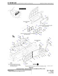
Power plant<br />
SR22T<br />
This slide covers those aspects of the SR22T included in AMM<br />
Chapter 71; Cowling and Induction air systems.<br />
Cowling description (AMM 71-10)<br />
The cowling for the SR22T consists of a three piece fiberglass<br />
cowl and a two piece aluminum NLG strut closeout panel. The<br />
fiberglass cowl is secured to the aircraft similarly to previous<br />
SR cowl systems.<br />
In addition to the fresh air NACA vent integral to the left lower<br />
cowl on SR22 2439 & subs, there are two NACA vents located<br />
on the left and right lower cowls which supply induction air<br />
through air filters to the turbochargers.<br />
Induction description (AMM 71-60)<br />
NACA vents on the left and right lower cowls provide fresh air<br />
to the turbochargers. The air passes through serviceable filters<br />
which require replacement at three years, five cleanings or 500<br />
hours (whichever occurs first). In the event of air filter icing or<br />
obstruction, a heated alternate air assembly is opened when a<br />
strip of magnets on the alternate air door is overcome by the<br />
induction vacuum. Alternate air then bypasses the filters.
Power plant<br />
Inspection/Check- Induction Air Filter (AMM 71-60)<br />
Remove cowling and induction air filters per AMM 71-60.<br />
Hold filter up to a bright light and examine filter elements<br />
for tears and holes. Visually inspect metal parts of air filter<br />
elements for damage. Replace filter element if damaged.<br />
Visual Inspection- Alternate air (AMM 71- 60)<br />
Check alternate air door for freedom of movement and<br />
correct MFD annunciation.<br />
Servicing- Induction Air Filter (AMM 71-60)<br />
Remove cowling and induction air filters per AMM 71-60.<br />
Using source of compressed air no greater than 10 psi,<br />
blow air through filter in opposite direction of airflow,<br />
holding air source at least 1” away from filter. Perform<br />
Inspection/Check-Induction Air Filter per AMM 71-60.<br />
SR22T
Power plant<br />
SR22T<br />
Inspection/Check - Exhaust System<br />
Visually inspect slip joints for bulges, cracks, or hot spots.<br />
Visually inspect stacks, risers, and elbows for burned areas, cracks, and loose parts or<br />
hardware. Check welded areas and seams for cracks. Replace parts that are cracked,<br />
burned, or worn.<br />
Visually inspect heat exchanger seams, joints and transitions with a flashlight and mirror<br />
or a flexible borescope for physical damage, cracks, corrosion, and burn-through. Inspect<br />
connecting flanges for security and proper mating.<br />
Perform exhaust leak test.<br />
1 Connect a high volume, dust-free, air pressure source to the exhaust tailpipe outlet.<br />
2 Apply 5 psi of air pressure to the exhaust system.<br />
3 Apply soapy water to the exhaust system and check for bubbling. If bubbling is<br />
found, replace the leaking exhaust components.<br />
Visually inspect exhaust stacks and transition unit for wear, leaks, cracks, or distortion.<br />
Replace worn, leaking, cracked, or distorted exhaust parts.<br />
Visually inspect exhaust manifold connections at cylinder for security of exhaust flange,<br />
gasket, and exhaust manifold fasteners.<br />
Visually inspect V-band clamps.<br />
1 Remove V-band clamp from exhaust tailpipe.<br />
2 Clean outer band of V-band clamp with crocus cloth.<br />
3 Inspect V-band clamp spot-weld (or rivet) areas for cracks and looseness.<br />
4 Using a flashlight and mirror, inspect corner radii of clamp inner segments for<br />
cracks. Inspect inner segment spacing.<br />
5 Inspect clamp outer band for flatness using a straight edge, especially within 2<br />
inches of spot-weld tabs that retain the T-bolt fastener. Verify clearance between<br />
clamp outer band and straight edge is less than 0.062 inches (1.57 mm).<br />
6 Verify 100% contact between inner segments and outer band.
Power plant<br />
SR22T<br />
Inspection/Check – Turbocharger AMM 81-20<br />
Visually inspect turbocharger housing and mounting bracket<br />
for general condition and<br />
security.<br />
Visually inspect oil fittings and surrounding area for evidence<br />
of oil leakage.<br />
Inspect turbocharger compressor.<br />
1 Remove induction air supply duct to turbocharger<br />
compressor and inspect compressor<br />
blades for evidence of foreign object damage.<br />
2 Turn compressor wheel by hand and check for freedom of<br />
rotation.<br />
3 Inspect the interior of air supply duct for general condition.<br />
4 Remove discharge duct from turbocharger compressor and<br />
inspect interior for evidence<br />
of oil. If there is evidence of oil in the duct, further inspection of<br />
turbocharger<br />
is required to determine cause and source of oil.<br />
Remove turbocharger exhaust stack and inspect turbine wheel<br />
for damage, freedom of<br />
rotation, and evidence of oil.<br />
Lubricate turbocharger link rod pins. (Refer to 12-20)
Power plant inspection<br />
SR22T
SR22T<br />
Power plant inspection; 25 hours
SR22T<br />
Power plant inspection; 25 hours
SR22T<br />
Power plant inspection; 50 hours
Power plant inspection; 100 hours<br />
SR22T
Operational Inspection (SID97-3E)<br />
• 22T-0001 & subs: Functional Inspection of Fuel Injection<br />
System in accordance with the manufacturer’s approved<br />
Instructions For Continued Airworthiness after engine<br />
installation,<br />
every 100 hours, at annual, or fuel system component<br />
replacement. Fuel Pump setup should be performed<br />
as follows:<br />
• At 600 RPM set un-metered pressure to 7.0 - 9.0 psi.<br />
.At 600 RPM, set idle cutoff RPM rise to 30-50 RPM.<br />
• At 2500 RPM and Boost Pump set to BOOST, reference the<br />
MFD gages and set Manifold Pressure and Fuel Flow per the<br />
following graph. Set un-metered pressure to 20.5 - 23.5 psi.<br />
SR22T<br />
Using Portatest unit;<br />
Connect the<br />
unmetered Portatest<br />
hoses to the throttle<br />
metering valve as you<br />
would for a non-turbo<br />
SR22 (you will need -<br />
6 adapters as the<br />
fuels lines are 3/8” on<br />
the SR22T).<br />
Using 0-60 psi gauge;<br />
Disconnect the<br />
unmetered (-6) fuel line<br />
to the throttle metering<br />
valve and insert the -6<br />
swivel run tee. Connect<br />
the tee leg to the<br />
unmetered 0-60 PSI<br />
gauge
Teledyne Continental Motors TSIO-550<br />
550-K<br />
Familiarization Training for the<br />
SR22T
TSIO550K1B<br />
Turbo<br />
Supercharged<br />
Injected<br />
Opposed<br />
550 Cubic Inches<br />
K Model Designation<br />
1B Customer<br />
Specification
Basic Engine Specification<br />
*as installed in SR22T<br />
• Firing Order 1-6-3-2-5-41<br />
• Compression Ratio 7.5:1<br />
• Rated Power<br />
– 315 HP (installed), 2500 RPM @ 36.5 inHg MAP (de-<br />
rated from 37.5 inHg MAP)<br />
• Idle 600 RPM<br />
• Weight 555.1 pounds (dry with TCM supplied<br />
accessories)
Engine Includes<br />
• Top Mounted Induction System, Including<br />
Dual Intercoolers<br />
• Pressurized Ignition System<br />
• Fuel Injection System with Aneroid Equipped<br />
Fuel Pump<br />
• Bottom Mounted Exhaust System<br />
• Twin Turbochargers with Single Wastegate,<br />
Sloped Controller and Oil System<br />
• Dual, Rear Mounted Accessory Drive Pads<br />
• Provision for Hydraulic Propeller Governor
Turbo & Induction Systems<br />
THROTTLE<br />
AFTERCOOLER<br />
WASTEGATE<br />
&<br />
WASTEGATE<br />
ACTUATOR<br />
ENGINE<br />
CYLINDER<br />
COMPRESSOR<br />
WHEEL<br />
OIL<br />
INLET<br />
EXHAUST GAS<br />
DISCHARGE<br />
OIL FROM<br />
WASEGATE<br />
OIL OUT<br />
TO ENGINE<br />
ENGINE EXHAUST GAS FLOW<br />
AMBIENT AIR<br />
INLET<br />
OIL<br />
OUTLET<br />
TURBINE<br />
WHEEL<br />
UPPERDECK PRESSURE<br />
MANIFOLD PRESSURE
Turbo & Induction Systems<br />
AFTERCOOLER<br />
BALANCED<br />
INDUCTION<br />
SLOPED<br />
CONTROLLER<br />
OVERBOOST<br />
PRESSURE<br />
RELIEF VALVE<br />
SONIC<br />
VENTURI<br />
CONNECTION<br />
AFTERCOOLER
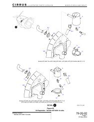
Turbocharger Exploded View<br />
Turbine<br />
Housing<br />
Turbine<br />
Center<br />
Housing<br />
Compressor<br />
Compressor<br />
Housing
Turbocharger Operation<br />
• Exhaust gases exit the cylinder and flow through the<br />
exhaust system to the turbocharger turbine inlet<br />
• The exhaust gas flow provides turbine wheel rotation<br />
and exits through the turbine housing discharge port<br />
and tailpipe<br />
• The turbine wheel drives the compressor wheel which<br />
is connected by a common shaft<br />
• During normal operation the turbocharger can reach<br />
speeds in excess of 100,000 RPM
Turbocharger Operation<br />
• The center shaft runs in an<br />
aluminum-bronze bearing and is<br />
supported by pressurized oil during<br />
operation<br />
• Prior to engine shut down after flight<br />
or a full power ground run, operate<br />
the engine at 800 to 1000 RPM for<br />
approximately 5 minutes for the<br />
turbocharger to cool down in order<br />
to prevent coking of the oil in the<br />
turbocharger and potential oil<br />
starvation of the bearings
Wastegate Valve<br />
• The wastegate is hydraulically<br />
actuated by engine oil pressure<br />
– Oil pressure is modulated<br />
through the sloped controller<br />
• Increasing oil pressure closes<br />
the butterfly valve to increase<br />
turbocharger output<br />
• Decreasing oil pressure opens<br />
the butterfly valve to decrease<br />
turbocharger output
Wastegate Maintenance<br />
• Inspect and lubricate the<br />
butterfly valve shaft with<br />
“Mouse Milk” at regular<br />
intervals<br />
• Routinely inspect the dry<br />
bay drain for oil; this<br />
would be a sign of the<br />
piston seal leaking<br />
DRY BAY DRAIN
Sloped Controller<br />
• The sloped controller references<br />
upper deck pressure and manifold<br />
pressure to maintain a preset<br />
pressure differential across the<br />
throttle plate<br />
• As the throttle plate is modulated<br />
and manifold pressure changes,<br />
the sloped controller reacts to<br />
maintain the preset differential to<br />
deck pressure<br />
• This action moves the oil control<br />
valve in the lower housing of the<br />
sloped controller to increase or<br />
decrease oil pressure output from<br />
the wastegate valve<br />
ANEROID<br />
BELLOWS<br />
ASSEMBLY<br />
MANIFOLD<br />
PRESSURE<br />
SENSING<br />
PORT<br />
DIAPHRAGM<br />
DECK<br />
PRESSURE<br />
SENSING<br />
PORT<br />
OIL INLET<br />
PORT<br />
ADJUSTMENT<br />
SCREW<br />
POPPET<br />
POPPET SEAT<br />
OIL DRAIN<br />
PORT
Aftercooler<br />
• Aftercoolers are installed between the<br />
compressor discharge port of the<br />
turbocharger and the throttle inlet<br />
• The aftercooler is an air-to<br />
to-air heat<br />
exchanger<br />
• Aftercoolers are used to reduce the<br />
temperature of the air delivered to the<br />
engine in order to:<br />
– Maintain detonation margin<br />
– Increase charge air density<br />
– Increase engine performance
Overboost Valve<br />
• Relief valve used to prevent over<br />
pressurization of the induction<br />
system in the event of a rapid<br />
throttle acceleration or<br />
malfunction of the turbo<br />
controlling system<br />
• Over pressurization can lead to<br />
cylinder degradation or<br />
detonation<br />
• Overboost valve is designed to<br />
“crack” at 39.5 inHg<br />
OPENING<br />
INDUCTION MANIFOLD<br />
AIR CAN ESCAPE<br />
SPRING<br />
AND BELLOWS<br />
VALVE
Fuel System<br />
5<br />
0<br />
METERED<br />
PRESSURE<br />
10 15 20<br />
25<br />
30<br />
Psid<br />
GAUGE<br />
OVERBOOST<br />
PRESSURE<br />
RELIEF VALVE<br />
SLOPED<br />
CONTROLLER<br />
FUEL MANIFOLD<br />
VALVE ASSEMBLY<br />
FUEL INJECTOR<br />
NOZZLE<br />
MANIFOLD<br />
PRESSURE<br />
FUEL<br />
PUMP<br />
UNMETERED<br />
PRESSURE<br />
20 30 10<br />
0<br />
psi<br />
50<br />
60<br />
GAUGE<br />
INLET FUEL<br />
FROM ACFT<br />
UNMETERED<br />
FUEL PRESSURE<br />
UPPER DECK<br />
PRESSURE<br />
METERED FUEL<br />
PRESSURE<br />
NOZZLE PRESSURE<br />
VAPOR RETURN
Aneroid Fuel Pump<br />
RECIRCULATION PATH<br />
TO RELIEF VALVE<br />
STOP PIN<br />
UPPER DECK<br />
REFERENCE AIR<br />
VAPOR SEPARATOR<br />
LESS INTERNAL RECIRCULATION<br />
MEANS GREATER OUTPUT PUMP<br />
PRESSURE AND FUEL FLOW<br />
Aneroid Detail<br />
VAPOR<br />
RETURN<br />
VAPOR<br />
RETURN<br />
VAPOR SEPARATOR<br />
BODY<br />
INLET FROM FUEL TANK<br />
RELIEF<br />
VALVE<br />
BY-PASS VALVE<br />
PUMP ASSEMBLY<br />
MIXTURE<br />
CONTROL SHAFT<br />
OUTLET TO<br />
FUEL METERING UNIT<br />
DRY BAY DRAIN
Fuel Injection Nozzles<br />
• The fuel injection<br />
nozzle is referenced to<br />
upper deck pressure air
Fuel Injection Nozzle Position<br />
• Ensure nozzle position<br />
is matched to the<br />
appropriate cylinder<br />
• Nozzle position is<br />
cylinder specific<br />
– Ensure nozzles are<br />
installed in the correct<br />
cylinder
Care and Inspection<br />
Oil Changes<br />
• Oil grade in accordance with<br />
latest revision of SIL 99-2<br />
• Visual examination of engine<br />
filter element<br />
• Spectrographic oil analysis
Care and Inspection<br />
Cylinders<br />
• Conduct borescope<br />
and cylinder<br />
differential pressure<br />
test in accordance<br />
with latest revision of<br />
SB03-3 3 at 100 hour<br />
and annual<br />
inspections
Care and Inspection<br />
Cylinders<br />
• Borescope<br />
– TCM recommends Lennox<br />
Instruments AutoScope<br />
• Differential Compression<br />
– TCM recommends Eastern<br />
Technologies Model E2M<br />
• Master orifice built in
Care and Inspection<br />
Turbochargers<br />
• Visual inspection of compressor and turbine<br />
wheel blades for cracking, chafing and<br />
contact with housing<br />
• Visual inspection of compressor and turbine<br />
housing for cracks and security of hardware<br />
• Perform inspections IAW Turbocharger<br />
manufacturers instructions
Care and Inspection<br />
Fuel Injection Nozzles<br />
• When removing or<br />
installing fuel injectors, use<br />
Burroughs #8165 or similar<br />
tool<br />
– This tool allows for the removal of<br />
the injector without removing<br />
induction tubes<br />
FUEL INLET<br />
NOZZLE<br />
COMPRESSOR<br />
DISCHARGE<br />
AIR PASSAGE<br />
SHROUD<br />
NOZZLE<br />
IDENTIFICATION<br />
NUMBER STAMPED<br />
ON<br />
HEX FLAT<br />
JET<br />
O‐RING<br />
AIR INLET<br />
O‐RING<br />
• Avoid any side load on the nozzle<br />
to prevent damage to the threads<br />
or cracking of the nozzle body<br />
• Clean nozzles by soaking in<br />
acetone, methyl ethyl ketone or<br />
lacquer thinner for a few hours and<br />
gently dry with compressed air
Care and Inspection<br />
Fuel Injection Nozzles<br />
• When installing, apply a small<br />
amount of anti seize compound<br />
(TCM P/N 646943 or Loctite 76732)<br />
to the threads, install a new washer<br />
and torque to 55-65 in-lbs<br />
• Shroud o-rings o<br />
(TCM P/N 630979-9)<br />
9)<br />
must be replaced any time the<br />
shroud is removed
Care and Inspection<br />
Fuel System Setup<br />
• Fuel system checks and adjustments per M-18 M<br />
Maintenance and Overhaul Manual<br />
– Verify at annual inspection and any time a fuel system<br />
component has been changed<br />
• TSIO-550<br />
550-K K engines installed in SR22T aircraft must be<br />
setup per <strong>Cirrus</strong> maintenance instructions<br />
– Methodology and equipment per latest revision of SID97-3<br />
• Model 20 ATM-C C Port-a-Test Unit<br />
• Calibrated pressure gauges<br />
– Setup values per <strong>Cirrus</strong> instructions
Questions?<br />
Give Us A Call<br />
Telephone<br />
US and Canada 888-826<br />
826-5465<br />
International 251-436<br />
436-8299<br />
E-Mail<br />
tcm.technical@teledyne.com