RARA OHM
RARA OHM
RARA OHM

Create successful ePaper yourself
Turn your PDF publications into a flip-book with our unique Google optimized e-Paper software.
<strong>RARA</strong><br />
<strong>RARA</strong> Electronics Corp.<br />
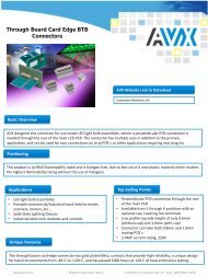
WIRE WOUND<br />
METAL CLAD RESISTORS<br />
- 1 -
IRH/ULH<br />
IRV/ULV<br />
Standard & UL<br />
60-500W<br />
1m-750Kohms<br />
IRN/ULN<br />
IRF/ULF<br />
IP65 Rating<br />
30-500W<br />
1-5.78Kohms<br />
IRB<br />
Economical<br />
48-120W<br />
1-1.3Kohms<br />
IRP<br />
High Power<br />
Assembly<br />
400-3.0KW<br />
0.1-1.4Kohms<br />
RoHS<br />
RoHS<br />
RoHS<br />
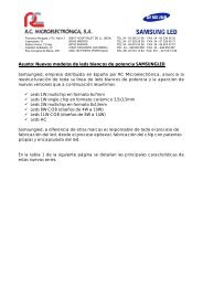
WIRE WOUND<br />
METAL CLAD RESISTORS<br />
IRV/ULV<br />
600-1.2KW<br />
Standard & UL<br />
0.1-160ohms<br />
IRS<br />
Economical<br />
Metal Clad<br />
30W, 50W<br />
1-500ohms<br />
RA<br />
Resistor<br />
Assembly<br />
80-2400W<br />
0.1-6.8Kohms<br />
- 2 -<br />
RoHS<br />
RoHS<br />
IRV<br />
1600-2800W<br />
Highest Power<br />
2.5-96ohms<br />
SPR114<br />
Network<br />
30W X 3<br />
0.1-20Kohms<br />
HRA<br />
High Power<br />
Assembly<br />
640-1.8KW<br />
0.1-840ohms<br />
LCA<br />
Low Cost<br />
Assembly<br />
1K-3KW<br />
0.5-560ohms<br />
RoHS<br />
RoHS
GENERAL SPECIFICATIONS<br />
IRV, ULV, IRH, ULH<br />
WIRE WOUND, METAL CLAD RESISTORS<br />
The IRV(V=vertical) & IRH(H=horizontal) models are our standard<br />
wire wound, metal clad resistors. The ULV<br />
and ULH models are UL approved versions of the IRV and<br />
IRH. These models have an extruded aluminum<br />
housing providing rugged and strong protection. Options include<br />
flying leads or tab terminals, inductive<br />
or non-inductive windings. The most common applications for<br />
these models are motor drives, braking<br />
and snubber applications and power sources for industrial<br />
equipment.<br />
Model<br />
Wattage Resistance Range [ohms]<br />
Rating On Inductive<br />
Heat Sink Tab Terminals Flying Leads<br />
Inductive<br />
Tab Terminals Flying Leads<br />
IRV/IRH 60<br />
ULV/ULH 60<br />
60W<br />
0.1-400<br />
0.1-375 0.1-400<br />
0.1-180<br />
0.1-180<br />
IRV/IRH 80<br />
ULV/ULH 80<br />
80W<br />
0.1-910<br />
0.1-281 0.1-910<br />
0.1-110<br />
0.1-110<br />
IRV/IRH 100<br />
ULV/ULH 100<br />
100W<br />
0.1-1.1K<br />
0.1-225 0.1-1.1K<br />
0.1-240<br />
0.1-225 0.1-240<br />
IRV/IRH 120<br />
ULV/ULH 120<br />
120W<br />
0.1-1.3K<br />
0.1-187 0.1-1.3K<br />
0.1-300<br />
0.1-187 0.1-300<br />
IRV/IRH 150<br />
ULV/ULH 150<br />
150W<br />
0.1-1.6K<br />
0.1-150 0.1-1.6K<br />
0.1-390<br />
0.1-150 0.1-390<br />
IRV/IRH 200<br />
ULV/ULH 200<br />
200W<br />
0.1-2.2K<br />
0.1-450 0.1-2.2K<br />
0.1-1.1K<br />
0.1-450 0.1-1K<br />
IRV/IRH 300<br />
ULV/ULH 300<br />
300W<br />
0.1-2.7K<br />
0.1-300 0.1-2.7K<br />
0.1-1.5K<br />
0.1-300 0.1-1.5K<br />
IRV/IRH 400<br />
ULV/ULH 400<br />
400W<br />
0.1-4.3K<br />
0.1-225 0.1-4.3<br />
0.1-2.2K<br />
0.1-225 0.1-2.2K<br />
IRV/IRH 500<br />
ULV/ULH 500<br />
500W<br />
0.1-6.8K<br />
0.1-180 0.1-6.8K<br />
0.1-3K<br />
0.1-180 0.1-3K<br />
CHARACTERISTICS<br />
Notes:<br />
Standard<br />
Tolerances<br />
+-2%(G)<br />
+-5%(J)<br />
+-10%(K)<br />
Optional<br />
Tolerances<br />
+-1.0%(F)<br />
+-0.5%(D)<br />
+-0.25%(C)<br />
+-0.1%(B)<br />
Extended<br />
Resistances<br />
>150K depending<br />
on model<br />
(please enquire)<br />
1/Temperature Range -55C to +200C<br />
2/Insulation Resistance 20Mohms minimum<br />
3/Dielectric Strength<br />
IRV/IRH<br />
ULV/ULH<br />
AC1500V, 3500V, 4500V, 5400V;Max. leakage current: 2mA<br />
See Note<br />
4/Temp. Coefficient +-260ppm/C maximum<br />
5/Short Time Overload +-[2%+0.05 ohms] 60W: 5XWatt Rating-5s.,80to500W: 10 X wattage rating-5s.<br />
6/Moisture Resistance +-[3%+0.05 ohms] 40C, 95% RH, DC100V case to terminal (500hrs.)<br />
7/Thermal Shock +-[2%+0.05 ohms] wattage rating 30min., -25C, 15minutes<br />
8/Vibration +-[1%+0.05 ohms] 10Hz-55Hz-10Hz (1min.),2hrs. each direction<br />
9/Moisture Load Life<br />
10/Load Life<br />
+-[3%+0.05 ohms] 40C,95%RH,0.1Xwattage rating, 1.5h.on,30min.off,500 hours<br />
+-[5%+0.05 ohms] wattage rating 1.5h. on, 30min. off, 500hours<br />
- 3 -
Note:<br />
ULV/ULH dielectric strength options of 1500V, 3500V, 4500V, 5400V are also available.<br />
Optional dielectric strength must be higher than standard (calculated by formula)<br />
SURFACE TEMPERATURE INCREASE VERSUS POWER LOAD (Heatsink size 400X400X3mm)<br />
DIMENSIONS<br />
Model<br />
L1 +-2 L2 +-2 L3 +-2<br />
W<br />
+-0.5<br />
Dimensions [mm] Weight [g]<br />
H<br />
+-0.5<br />
D1<br />
+-0.5<br />
D2<br />
+-0.5<br />
a b IRH IRV<br />
H/V 60 100 87 60 41 22 4.3 8.65 10 12 110 113<br />
H/V 80 150 137 110 41 22 4.3 8.65 10 12 195 189<br />
H/V 100 165 152 125 41 22 4.3 8.65 10 12 216 215<br />
H/V 120 182 169 142 41 22 4.3 8.65 10 12 245 241<br />
H/V 150 210 197 170 41 22 4.3 8.65 10 12 283 290<br />
H/V 200 165 146 125 60 30 5.3 12 13 17 485 447<br />
H/V 300 215 196 175 60 30 5.3 12 13 17 600 600<br />
H/V 400 265 246 225 60 30 5.3 12 13 17 770 780<br />
H/V 500 335 316 295 60 30 5.3 12 13 17 990 980<br />
- 4 -
DERATING CURVE<br />
FLYING LEADS<br />
Model 8mm 2<br />
5.5mm 2<br />
2mm 2<br />
1.25mm 2<br />
UL3512AWG10 UL3512AWG14<br />
IRH/V60-150 - - 0.1-0.99ohm 1ohm and up - -<br />
IRH/V200-<br />
0.1-0.99ohm 1-4.99ohm 5ohm and up - - -<br />
500<br />
IRH/V60-120 - - - - - 0.10ohm and up<br />
ULH/V150 - - - - - 0.11ohm and up<br />
ULH/V200 - - - - 0.1-0.15ohm 0.16ohm and up<br />
ULH/V300 - - - - 0.1-0.22ohm 0.23ohm and up<br />
ULH/V400 - - - - 0.1-0.30ohm 0.31ohm and up<br />
ULH/V500 - - - - 0.1-0.37ohm 0.38ohm and up<br />
ORDERING PROCEDURE EXAMPLE<br />
- 5 -
IRV/ULV 600-1200<br />
WIRE WOUND, METAL CLAD RESISTORS<br />
The IRV/ULV600-1200 (V=vertical) models<br />
are our standard higher power, wire wound,<br />
metal clad resistors.<br />
The ULV600-1200 are the UL approved<br />
versions of the IRV600-1200<br />
models. These models have an extruded<br />
aluminium housing providing strong and<br />
rugged protection. Options include flying<br />
leads or tab terminals and<br />
inductive or non-inductive windings. The<br />
most common applications for these models are: motor drives,<br />
braking and snubber applications and power sources for industrial equipment.<br />
SPECIFICATIONS<br />
Model<br />
Power<br />
Rating on<br />
Heatsink<br />
Resistance Range [ohms]<br />
Inductive<br />
Tab TP Tab TS Leads<br />
Non-Inductive<br />
Tab TP Tab TS Leads<br />
IRV600<br />
ULV600<br />
600W<br />
0.1-9<br />
0.1-9<br />
9.1-94<br />
9.1-94<br />
0.1-94<br />
0.1-94<br />
0.1-5.3<br />
0.1-5.3<br />
5.4-21.2<br />
5.4-21.2<br />
0.1-21.2<br />
0.1-21.2<br />
IRV800<br />
ULV800<br />
800W<br />
0.1-11<br />
0.1-11<br />
11.1-112<br />
11.1-112<br />
0.1-112<br />
0.14-112<br />
0.1-7.2<br />
0.1-7.2<br />
7.2-28.8<br />
7.2-28.8<br />
0.1-28.8<br />
0.14-28.8<br />
IRV1000<br />
ULV1000<br />
1000W<br />
0.1-18<br />
0.1-18<br />
18.1-140<br />
18.1-140<br />
0.1-140<br />
0.17-140<br />
0.1-9<br />
0.1-9<br />
9.1-36<br />
9.1-36<br />
0.1-36<br />
0.17-36<br />
IRV1200<br />
ULV1200<br />
1200W<br />
0.1-25<br />
0.1-25<br />
25.1-160<br />
25.1-75<br />
0.1-160<br />
0.21-160<br />
0.1-12<br />
0.1-12<br />
12.1-48<br />
12.1-48<br />
0.1-48<br />
0.21-48<br />
IRVavailable tolerances: +-0.5(D), +-1(F), +-2(G), +-5(J), +-10(K)<br />
ULV available tolerances: +-2(G), +-5(J), +-10(K)<br />
CHARACTERISTICS Values in [ ] mean change in ohmic value after test<br />
Temperature Range -55C to +200C<br />
Insulation Resistance 20MW minimum<br />
Dielectric Strength<br />
IRV<br />
ULV<br />
AC1500V, 3500V, 4500V, 5400V; Max. leakage current: 2mA<br />
See Note [1000V+(Voltage Rating X 2) for 1min.<br />
Temp. Coefficient ±260ppm/C maximum<br />
Short Time Overload<br />
±[2%+0.05W] 10 X Power rating-<br />
5seconds<br />
Moisture Resistance ±[3%+0.05W] 40C, 95% RH, DC100V case to terminal (500hrs.)<br />
Thermal Shock<br />
±[2%+0.05W] Power rating 30min.,<br />
25C,15minutes<br />
Vibration ±[1%+0.05W] 1Hz-55Hz-10Hz (1min.), 2hrs. each direction<br />
Moisture Load Life ±[3%+0.05W] 40C, 95% RH, 0.1 X Power rating, 1.5h. on, 30min. off, 500 hrs.<br />
Load Life<br />
±[5%+0.05W] Power rating 1.5hr. on, 30min. off,<br />
500hours<br />
- 6 -
Note:<br />
ULV/ULH dielectric strength options of AC1500V, 3500V, 4500V, 5400V also available<br />
Optional dielectric strength must be higher than standard (calculated by formula)<br />
SURFACE TEMPERATURE INCREASE VS POWER LOAD<br />
DIMENSIONS<br />
Model<br />
Dimensions [mm]<br />
L1+-2 L2+-2 L3+-2<br />
Weight<br />
IRV600 235 216 195 1165<br />
IRV800 285 266 245 1500<br />
IRV1000 335 316 295 1835<br />
IRV1200 405 386 365 2304<br />
- 7 -<br />
[g]
FLYING LEADS<br />
DERATING CURVE<br />
Model 8mm 2<br />
5.5mm 2<br />
UL 3512 AWG 10<br />
IRV600-1200 0.1-0.99ohms 1 ohm and up -<br />
ULV600 - - 0.11 ohms and up<br />
ULV800 - - 0.14 ohms and up<br />
ULV1000 - - 0.17 ohms and up<br />
ULV1200 - - 0.21 ohms and up<br />
ORDERING PROCEDURE EXAMPLE<br />
- 8 -
IRV1600-2800 HIGH POWER, WIRE<br />
WOUND, METAL CLAD RESISTORS<br />
The IRV1600-2800 (V=vertical) models are our highest power, wire wound,<br />
metal clad resistors. These models have an extruded aluminium housing<br />
providing strong and rugged protection. Options include flying leads or tab<br />
terminals and inductive or non-inductive windings. The most common<br />
applications for these models are: motor drives, braking and snubber<br />
applications and power sources for industrial equipment. These models are<br />
fully RoHS compliant.<br />
SPECIFICATIONS<br />
Model<br />
Rated Power<br />
Heat Sink Free Air<br />
Resistance Range<br />
Inductive<br />
IRV1600 1600W 570W 2.5-78<br />
IRV2000 2000W 650W 3.2-86<br />
IRV2400 2400W 720W 4.0-92<br />
IRV2800 2800W 730W 4.5-96<br />
Resistance<br />
Tolerance<br />
F[+-01%]<br />
J[+-05%]<br />
K[+-10%]<br />
CHARACTERISTICS Values in [ ] mean change in ohmic value after test<br />
Temperature Range -55C to +280C<br />
Insulation Resistance 20MW minimum<br />
Dielectric Strength AC1500V, 2500V, 3500V, 4500V for 1 min.; Max. leakage current: 2mA<br />
Temp. Coefficient ±260ppm/C maximum<br />
Short Time Overload ±[3%+0.05W] 5-10 X Power rating-5seconds<br />
Moisture Resistance ±[3%+0.05W] 40C, 95% RH, DC100V case to terminal (500hrs.)<br />
Thermal Shock ±[5%+0.05W] Power rating 30min., -40C,15minutes<br />
Vibration ±[2%+0.05W] 10Hz-55Hz-10Hz (1min.), 2hrs. each direction<br />
Moisture Load Life ±[3%+0.05W] 40C, 95% RH, 0.1XPower rating, 1.5h. on, 30min. off, 500 hrs.<br />
Load Life ±[5%+0.05W] Power rating 1.5hr. on, 30min. off, 500hours<br />
- 9 -
SURFACE TEMPERATURE INCREASE VS POWER LOAD & DERATING<br />
DIMENSIONS<br />
Model<br />
Dimensions [mm]<br />
L1+-2 L2+-2 L3+-2 H+-1 W+-0.5<br />
IRV1600 330 315 290 100 50 2.5<br />
IRV2000 440 385 360 100 50 3.1<br />
IRV2400 480 465 440 100 50 3.7<br />
IRV2800 550 535 510 100 50 4.3<br />
- 10 -<br />
Weight<br />
[Kg]
FLYING LEADS<br />
Model 5.5mm 2<br />
2mm 2<br />
UL3512 AWG14 LKGB-600V 2mm 2<br />
IRV1600 Optional 2.5ohm + Optional Optional<br />
IRV2000 Optional 3.2ohm + Optional Optional<br />
IRV2400 Optional 4.0ohm + Optional Optional<br />
IRV2800 Optional 4.5ohm + Optional Optional<br />
ORDERING PROCEDURE EXAMPLE<br />
- 11 -
GENERAL SPECIFICATIONS<br />
IRN, ULN, IRF, ULF SLIM PROFILE<br />
WIRE WOUND, METAL CLAD RESISTORS<br />
IP65 RATING AVAILABLE<br />
The IRN(N=narrow and flat) & IRF(F=flat) models are metal-clad, wirewound,<br />
high-power, extremely low inductance resistors designed for<br />
industrial and other applications where space is at a premium and<br />
performance is a must. The ULN and ULF are UL approved versions of these<br />
models. Our extruded aluminium housing provides rugged and strong<br />
protection. The flat design allows excellent heat dissipation. These models<br />
are available with flying leads or tab terminals. The most common<br />
applications for these models are motor drives, braking and snubber<br />
applications and power sources for industrial equipment.<br />
Model<br />
Wattage Rating on Heat<br />
Sink<br />
Resistance Range [ohms] Tolerances<br />
IRN50/ULN50C 50W 1-420<br />
IRN100/ULN100C<br />
IRN150/ULN150C<br />
100W<br />
150W<br />
1-1.1K<br />
1-1.75K<br />
+-0.5(D)<br />
IRF100/ULF100C<br />
IRF150/ULF150C<br />
100W<br />
150W<br />
1-1.1K<br />
1-1.75K<br />
+-1.0(F)<br />
IRF200/ULF200C<br />
IRF250/ULF250C<br />
200W<br />
250W<br />
1-2.2K<br />
1-2.79K<br />
+-2.0(G)<br />
IRF300/ULF300C<br />
IRF400<br />
300W<br />
400W<br />
1-3.5K<br />
1-4.45K<br />
+-5.0(J)<br />
ULF400C<br />
IRF500<br />
400W<br />
500W<br />
1-3.08K<br />
1-5.78K<br />
+-10(K)<br />
ULF500C 500W 1-2.46K<br />
CHARACTERISTICS<br />
1/Temperature Range Cement: -55C to +200C, Silicone: -55-150C<br />
2/Insulation Resistance 20Mohms minimum<br />
IRN/IRF AC1500V, 2500V, 3000V, 4500V; Max. leakage current: 2mA<br />
3/Dielectric Strength<br />
ULN/ULF See Note 2<br />
4/Temp. Coefficient +-260ppm/C maximum<br />
5/Short Time Overload +-[1%+0.05 ohms] 5 X Power Rating-5sec.<br />
6/Moisture Resistance +-[2%+0.05 ohms] 40C, 95% RH, DC100V case to terminal (500hrs.)<br />
7/Thermal Shock +-[1%+0.05 ohms] Power rating 30min., -25C, 15minutes<br />
8/Vibration +-[1%+0.05 ohms] 10Hz-55Hz-10Hz (1min.), 2hrs. each direction<br />
9/Moisture Load Life +-[2%+0.05 ohms] 40C,95% RH, 0.1 X Power rating, 1.5h. on, 30min. off, 500 hours<br />
10/Load Life +-[5%+0.05 ohms] Power rating, 1.5h. on, 30min. off, 500 hours<br />
Note1:<br />
ULN/ULF dielectric strength options of 1500V, 3500V, 4500V are also available.<br />
Optional dielectric strength must be higher than standard (calculated by formula)<br />
Note2:<br />
Less than 50V: 500V 1 min.<br />
50-600V: [1000V+(voltage rating X 2) 1 min.<br />
601-1500V: [2000V+(voltage rating X 2.25) 1 min.<br />
- 12 -
SURFACE TEMPERATURE INCREASE VERSUS POWER LOAD<br />
(Heatsink size 400X400X3mm)<br />
DIMENSIONS<br />
Model<br />
Dimensions [mm]<br />
L1+-1 L2+-0.3 W1+-0.3 W2+-0.3<br />
Weight [g]<br />
IRN50/ULN50 70 50 60 50 100<br />
IRN100/ULN100 120 100 60 50 160<br />
IRN150/ULN150 170 150 60 50 220<br />
IRF100/ULF100 90 70 80 70 155<br />
IRF150/ULF150 120 100 80 70 200<br />
IRF200/ULF200 150 130 80 70 245<br />
IRF250/ULF250 180 160 80 70 290<br />
IRF300/ULF300 210 190 80 70 335<br />
IRF400/ULF400 270 250 80 70 430<br />
IRF500/ULF500 330 310 80 70 525<br />
- 13 -
FLYING LEADS<br />
Model 2mm 2<br />
1.25mm 2<br />
IRN/F 50-150 - 1ohm -<br />
IRF200 1-4ohm 4.1ohm -<br />
IRF250 1-5ohm 5.1ohm -<br />
IRF300 1-6ohm 6.1ohm -<br />
IRF400 1-8ohm 8.1ohm -<br />
IRF500 1-10ohm 10.1ohm -<br />
ULN/F 50-500 - - 1ohm<br />
DERATING CURVE<br />
ORDERING PROCEDURE EXAMPLE<br />
1 IRF,IRN,ULF,ULN100-500 on heat sink; IRN,ULN50 free air<br />
2 IRF,IRN,ULF,ULN100 in free air<br />
3 IRF,IRN,ULF,ULN150 in free air<br />
4 IRF,IRN,ULF,ULN200 in free air<br />
5 IRF,IRN,ULF,ULN250-300 in free air<br />
6 IRF,IRN,ULF,ULN400 in free air<br />
7 IRF,IRN,ULF,ULN500 in free air<br />
Heat Sink Size:<br />
IRF,IRN,ULF,ULN100-200: 200X200X3mm<br />
IRF,ULF250-400: 400X400X3mm<br />
IRF,ULF500: 600X600X3mm<br />
- 14 -<br />
UL 3512 AWG 16
SPECIFICATIONS<br />
ECONOMICAL<br />
WIRE WOUND, METAL CLAD RESISTORS<br />
The IRS30, IRS50 are slim and flat economical<br />
resistors. These models are ideal for applications<br />
where space<br />
and funds are at a premium. The most common<br />
applications for these models are motor drives,<br />
braking<br />
and snubber applications and power sources for<br />
industrial equipment.<br />
MODEL<br />
Wattage Rating<br />
On Heat Sink [W]<br />
Resistance<br />
Range [ohms]<br />
Dimensions<br />
L1+-1 L2+-1<br />
Weight<br />
[g]<br />
IRS 30 30 1 - 420 65 57 65<br />
IRS 50 50 1-500 90 78 50<br />
Available Tolerances: +-0.5(D), +-1.0(F), +-2.0(G), +-10(K)<br />
DIMENSIONS<br />
CHARACTERISTICS<br />
Temperature Range<br />
-55-<br />
200C<br />
Insulation<br />
Resistance<br />
20Mohm Minimum<br />
Dielectric Strength Available Options: AC1500V, 2500V; Max. Leakage Current: 2mA<br />
Temp. Coefficient +-260ppm/C Maximum<br />
Short Time Overload +-[2%+0.05ohms] 5 X Power Rating, 5sec.<br />
Thermal Shock +-[2%+0.05ohms] Power Rating 30min., -25C 15min.<br />
Load Life +-[5%+0.05ohms] Power Rating 1.5hrs. on, 30min. off, 500hrs.<br />
- 15 -
SURFACE TEMPERATURE INCREASE VS POWER LOAD<br />
DERATING CURVE<br />
ORDERING PROCEDURE EXAMPLE<br />
1/ On chassis, 30W, 50W (heatsink size 200X200X3mm)<br />
2/ Free Air, 30W<br />
3/ Free Air, 50W<br />
- 16 -
SPECIFICATIONS<br />
CHARACTERISTICS<br />
SPR114 30W X 3<br />
NETWORK RESISTORS<br />
These Are aluminium hosed, non-inductive, resistor networks. These are mountable on chassis<br />
toutilize heatsink effect. These models exhibit high stability at conventional power<br />
ratings. The SPR114 has three isolated resistors.<br />
Model Power Rating [W] Resistance Range [ohms]<br />
75 X 3<br />
Tolerance<br />
SPR114 30 X 3<br />
150 X 3<br />
300 X 3<br />
400 X 3<br />
J(+-5%)<br />
Temperature Range -55C to 200C<br />
Insulation Resistance 20Mohms minimum<br />
Dielectric Strength Available Options: AC200V; Max. 1 min.; Leakage Current: 2mA<br />
Temperature Coefficient +-260ppm/C maximum<br />
ORDERING PROCEDURE EXAMPLE<br />
- 17 -
GENERAL SPECIFICATIONS<br />
ECONOMICAL<br />
WIRE WOUND, METAL CLAD RESISTORS<br />
IRB60, 80, 120 metal clad, wire wound resistors are ideal for applications that<br />
require 60W,80W,120W or less and<br />
are on a budget. These models come in a durable metal case have flying leads.<br />
Resistance Range [Ω]<br />
MODEL Power rating [W]<br />
Inductive Non-Inductive<br />
IRB 60 60 0.1-270 0.1-56<br />
IRB 80 80 0.1-910 0.1-110<br />
IRB120 120 0.1-1.3K 0.1-300<br />
Available Tolerances: G (+-2%), H (+-3%), J (+-5%), K (+-10%), M (+-20%)<br />
DIMENSIONS<br />
DIMENSIONS<br />
MODEL<br />
L1 L2 D W L3 H<br />
IRB60 100+-1.5 90+-1.5 5+-0.2 32.3+-0.5 75+-1 12.3+-1<br />
IRB80 150+-2 140+-2 4.2+-0.5 34+-1 130+-2 20+-1<br />
IRB120 182+-1 170+-1 5+-0.2 44+-1 150+-1 13+-0.5<br />
CHARACTERISTICS Values in [ ] mean change in ohmic value after test<br />
Temperature Range -55C to 200C<br />
Insulation Resistance 20Mohm min.<br />
Dielectric Strength Available options: AC 1500V,3500V,4500V,5400V MAX. leakage current: 2mA<br />
Temp. Coefficient +- 260ppm/C maximum<br />
Short time overload (2%+0.05Ω) 60W:5×wattage rating, 80W, 120W:10×wattage rating-5 sec.<br />
Moisture Resistance (3%+0.05Ω) 40C, 95% RH, DC100V case to terminal (500hrs.)<br />
Thermal Shock (2%+0.05Ω) wattage rating 30 min., -25C, 15 min.<br />
Vibration (1%+0.05Ω) 10Hz-55Hz-10Hz (1 min.), 2hrs.each direction<br />
Moisture Load Life (3%+0.05Ω) 40C, 95%RH, 0.1×wattage rating, 1.5hrs.on, 30min. off, 1000hrs.<br />
Load Life (5%+0.05Ω) wattage rating 1.5h. on, 30min.off, 1000hrs.<br />
- 18 -
SURFACE TEMPERATURE INCREASE CURVE<br />
DERATING CURVE<br />
ORDERING PROCEDURE EXAMPLE<br />
- 19 -
GENERAL SPECIFICATIONS<br />
RA RESISTOR<br />
ASSEMBLIES<br />
The RA series of power, metal clad, wire wound resistors are designed for<br />
use in power inverters. The basis for<br />
these models is an IRH or IRV resistor surrounded by a metal case, which<br />
conforms to international safety<br />
specifications . The steel case is powder coated and baked for durability.<br />
Model<br />
Resistor<br />
Type<br />
Inside<br />
Wattage<br />
Rating in<br />
Free Air<br />
Resistance Range [ohms]<br />
Non-<br />
Inductive<br />
Inductive<br />
RA080 IRH80 80 0.1-910 0.1-110<br />
RA100 IRH100 90 0.1-1.1K 0.1-240<br />
RA200 IRH200 140 0.1-2.2K 0.1-1K<br />
RA300 IRH300 210 0.1-2.7K 0.1-1.5K<br />
RA400 IRH400 240 0.1-4.3K 0.1-2.2K<br />
RA500 IRH500 300 0.1-6.8K 0.1-3K<br />
RA600 IRV600 320 0.1-94 0.1-23<br />
RA800 IRV800 360 0.1-112 0.1-28<br />
RA1000 IRV1000 400 0.1-140 0.1-36<br />
RA1200 IRV1200 420 0.1-160 0.1-48<br />
RA1600 IRV1600 570 2.5-78 /<br />
RA2000 IRV2000 650 3.2-86 /<br />
RA2400 IRV2400 710 4.0-92 /<br />
CHARACTERISTICS<br />
1/Temperature Range<br />
+200C<br />
Resistance<br />
Tolerance<br />
+-0.5(D)<br />
+-1.0(F)<br />
+-2.0(G)<br />
+-5.0(J)<br />
+-10(K)<br />
-55C to<br />
2/Insulation Resistance 20Mohms<br />
minimum<br />
3/Dielectric Strength Available options: 1500, 3500, 4500, 5400 (VAC); Max Leakage Current: 2mA<br />
4/Temp. Coefficient +-260ppm/C maximum<br />
5/Short Time Overload +-[2%+0.05 ohms] 10 X wattage rating 5s.<br />
6/Moisture Resistance +-[3%+0.05 ohms] 40C, 95% RH, DC100V case to terminal (500hrs.)<br />
7/Thermal Shock +-[2%+0.05 ohms] Wattage rating 30min., -25C, 15minutes<br />
- 20 -
DIMENSIONS<br />
Model<br />
Weight<br />
[g]<br />
Dimensions [mm]<br />
W+-1.5 H+-1.5 D+-2 D1+-1.5 D2+-2<br />
RA080 980 78.5 67 254 240 224<br />
RA100 1000 78.5 67 254 240 224<br />
RA200 2415 93.5 105 440 426 410<br />
RA300 2530 93.5 105 440 426 410<br />
RA400 2700 93.5 105 440 426 410<br />
RA500 2920 93.5 105 440 426 410<br />
RA600 3095 93.5 105 440 426 410<br />
RA800 3430 93.5 105 440 426 410<br />
RA1000 3725 93.5 105 440 426 410<br />
RA1200 4194 93.5 105 510 426 480<br />
RA1600 5900 93.5 147 615 600 584<br />
RA2000 6500 93.5 147 615 600 584<br />
RA2400 7100 93.5 147 615 600 584<br />
ORDERING PROCEDURE EXAMPLE<br />
- 21 -
HRA RESISTOR<br />
ASSEMBLIES<br />
The HRA series of power, metal clad, wire wound resistors are designed for use in high power inverters.<br />
The basis for these models is an IRV resistors surrounded by a metal case, which conforms to international<br />
safety specifications. The steel case is powder coated and baked for durability.<br />
GENERAL SPECIFICATIONS<br />
Power Rating Resistance Range [ohms]<br />
Model<br />
HRA1600<br />
HRA2000<br />
HRA2400<br />
HRA3000<br />
HRA4000<br />
Internal<br />
Resistor<br />
2XIRV800<br />
2XIRV1000<br />
3XIRV800<br />
3XIRV1000<br />
4XIRV1000<br />
Free Air<br />
640W<br />
800W<br />
960W<br />
1100W<br />
1400W<br />
Fan<br />
960W<br />
1200W<br />
1440W<br />
1650W<br />
2100W<br />
Inductive<br />
0.1-224<br />
0.1-280<br />
0.1-336<br />
0.1-420<br />
0.1-560<br />
Non-Inductive<br />
0.1-56<br />
0.1-72<br />
0.1-84<br />
0.1-108<br />
0.1-144<br />
HRA5000<br />
HRA6000<br />
HRA7000<br />
HRA8000<br />
HRA9000<br />
HRA10000<br />
5XIRV1000<br />
6XIRV1000<br />
7XIRV1000<br />
8XIRV1000<br />
9XIRV1000<br />
10XIRV1000<br />
1600W<br />
1800W<br />
2100W<br />
2400W<br />
2700W<br />
3000W<br />
2400W<br />
2700W<br />
3150W<br />
3600W<br />
4050W<br />
4500W<br />
0.1-700<br />
0.1-840<br />
0.1-980<br />
0.1-1120<br />
0.1-1260<br />
0.1-1400<br />
0.1-180<br />
0.1-216<br />
0.1-252<br />
0.1-288<br />
0.1-324<br />
0.1-360<br />
CHARACTERISTICS<br />
Resistance<br />
Tolerance<br />
+-0.5(D)<br />
+-1.0(F)<br />
+-2.0(G)<br />
+-5.0(J)<br />
+-10(K)<br />
1/Temperature Range -55C to<br />
+200C<br />
2/Insulation Resistance 20Mohms<br />
minimum<br />
3/Dielectric Strength Available options: 1500, 2500, 3500 (VAC); Max Leakage Current: 2mA<br />
4/Temp. Coefficient +-260ppm/C maximum<br />
5/Short Time Overload +-[2%+0.05 ohms] 10 X wattage rating 5s.<br />
6/Moisture Resistance +-[3%+0.05 ohms] 40C, 95% RH, DC100V case to terminal (500hrs.)<br />
7/Thermal Shock +-[2%+0.05 ohms] Wattage rating 30min., -25C, 15minutes<br />
- 22 -
DIMENSIONS<br />
Model<br />
Weight<br />
Dimensions [mm]<br />
[Kg] W±5 D±5 H±3 W1±2 D1±2<br />
HRA1600 8.3 250 510 110 215 360<br />
HRA2000 9 250 510 110 215 360<br />
HRA2400 9.8 250 510 110 215 360<br />
HRA3000 10.8 250 510 110 215 360<br />
HRA4000 14.2 388 510 110 356 360<br />
HRA5000 16.0 388 510 110 356 360<br />
HRA6000 18.0 388 510 190 356 360<br />
HRA7000 20.5 388 510 190 356 360<br />
HRA8000 22.3 388 510 190 356 360<br />
HRA9000 24.2 388 510 190 356 360<br />
HRA10000 26.0 388 510 190 356 360<br />
ORDERING PROCEDURE EXAMPLE<br />
These models come with multiple conduit knockouts for easy wiring.<br />
The enclosure is well ventilated and meets int’l safety specs.<br />
- 23 -
GENERAL SPECIFICATIONS<br />
IRP HIGH POWER<br />
RESISTOR ASSEMBLIES<br />
Free Air<br />
Resistance Range [ohms]<br />
Model<br />
Power<br />
Inductive Non-Inductive<br />
Rating [W]<br />
IRP1000 400 0.1-140 0.1-36<br />
IRP2000 800 0.1-280 0.1-72<br />
IRP3000 1100 0.1-420 0.1-108<br />
IRP4000 1400 0.1-560 0.1-144<br />
IRP5000 1600 0.1-700 0.1-180<br />
IRP6000 1800 0.1-840 0.1-216<br />
IRP7000 2100 0.1-980 0.1-252<br />
IRP8000 2400 0.1-1120 0.1-288<br />
IRP9000 2700 0.1-1260 0.1-324<br />
IRP10000 3000 0.1-1400 0.1-360<br />
CHARACTERISTICS<br />
1/Temperature Range<br />
+200C<br />
The IRP high power resistor line can handle power of<br />
up to 3000W in free air. These models are comprised<br />
of multiple resistors housed in a rugged steel<br />
protective cover. The base is zinc plated steel. The<br />
cover is powder coated which is baked, rendering it<br />
extremely strong. The major application for this<br />
model range is high power inverter braking resistors.<br />
Resistance<br />
Tolerance<br />
+-0.5(D)<br />
+-1.0(F)<br />
+-2.0(G)<br />
+-5.0(J)<br />
+-10(K)<br />
-55C to<br />
2/Insulation Resistance 20Mohms<br />
minimum<br />
3/Dielectric Strength Available options: 1500, 2500, 3500 (VAC); Max Leakage Current: 2mA<br />
4/Temp. Coefficient +-260ppm/C maximum<br />
5/Short Time Overload +-[2%+0.05 ohms] 10 X wattage rating 5s.<br />
6/Moisture Resistance +-[3%+0.05 ohms] 40C, 95% RH, DC100V case to terminal (500hrs.)<br />
7/Thermal Shock +-[2%+0.05 ohms] Wattage rating 30min., -25C, 15minutes<br />
- 24 -
DIMENSIONS<br />
Dimensions[mm]<br />
Model<br />
Weight [Kg]<br />
L1+-2 L2+-2 W1+-2 W2+-2 H1+-2 H2+-2<br />
IRP1000 320 7.1<br />
IRP2000 320 9.0<br />
IRP3000 320 120 75<br />
10.8<br />
IRP4000 430 14.2<br />
IRP5000 430<br />
16.0<br />
530 510<br />
240<br />
IRP6000 320 18.0<br />
IRP7000 430 20.5<br />
IRP8000 430 215 170<br />
22.3<br />
IRP9000 430 24.2<br />
IRP10000<br />
430<br />
26.0<br />
ORDERING PROCEDURE EXAMPLE<br />
- 25 -
GENERAL SPECIFICATIONS<br />
MODEL<br />
LCA<br />
LOW COST RESISTOR ASSEMBLY<br />
Internal<br />
Resistor Type<br />
These economical and powerful components comprise two, three<br />
or four high power resistors housed in partial steel covers at each<br />
end. These rugged, powder coated covers ensure an excellent<br />
seal. The internal resistors use aluminum plates at each end<br />
instead of our standard cement molding. This innovation reduces<br />
construction time and reduces cost, at no reduction of<br />
performance. The major application of this exciting new model is<br />
highpower inverter braking units.<br />
Power Rating<br />
in free air [W]<br />
Resistance<br />
Range[ohms]<br />
LCA 3.2K IRV1600X2 1.0k 2.3 - 160<br />
LCA 4.0K IRV2000X2 1.2k 3.0 - 220<br />
LCA 4.8K IRV2400X2 1.3k 4.0 - 280<br />
LCA 5.6K IRV2800X2 1.4k 4.5 - 270<br />
LCA 4.8K IRV1600X3 1.3k 0.75 - 265<br />
LCA 6.0K IRV2000X3 1.4k 1.0 - 330<br />
LCA 7.2K IRV2400X3 1.5k 1.5 - 420<br />
LCA 9.6K IRV2800X3 1.6k 1.5 - 390<br />
LCA 6.4K IRV1600X4 1.7k 0.5 - 340<br />
LCA 8.0K IRV2000X4 1.9k 0.75 - 440<br />
LCA 9.6K IRV2400X4 2.1k 1.0 - 560<br />
LCA 11.2K IRV2800X4 2.3k 1.1 - 520<br />
Resistance<br />
Tolerance<br />
J[+-5%]<br />
K[+-10%]<br />
CHARACTERISTICS Values in [ ] mean change in ohmic value after test<br />
Temperature Range -55C - 275C<br />
Insulation Resistance 20Mohms min.<br />
Dielectric Strength Available options: AC1500V, 3500V(Max. leakage current: 2mA)<br />
Temp. Coefficient +- 260ppm/C max.<br />
Short Time Overload +- [2%+0.05 ohms] 10 X Power rating 5 secs.<br />
Moisture Resistance +- [3%+0.05 ohms] 40C, 95% RH, DC100V case to terminal, 500hrs.<br />
Thermal Shock +- [2%+0.05 ohms] Power rating 30min., -40C 15 min.<br />
Vibration +- [2%+0.05 ohms] 10Hz-55Hz-10Hz (1 min), 2hrs each direction.<br />
Load life +- [5%+0.05 ohms] Power rating 1.5hrs on, 30min off, 500hrs.<br />
- 26 -
DIMENSIONS<br />
Model<br />
Weight<br />
Dimensions[mm]<br />
[Kg] L1+-5 L2+-3 W1+-2 W2+-2<br />
LCA 3.2K 6.5 484 463<br />
LCA 4.0K 7.5 554 533<br />
LCA 4.8K 8.5 634 613<br />
LCA 5.6K 10.0 704 683<br />
LCA 4.8K 9.0 484 463<br />
LCA 6.0K 11.0 554 533<br />
LCA 7.2K 13.0 634 613<br />
LCA 9.6K 15.0 704 683<br />
LCA 6.4K 12.0 484 463<br />
LCA 8.0K 14.0 554 533<br />
LCA 9.6K 16.5 634 613<br />
LCA 11.2K 19.0 704 683<br />
- 27 -<br />
134 79<br />
204<br />
274<br />
140
ORDERING PROCEDURE EXAMPLE<br />
- 28 -