Sonderdruck WIP / CIP - Glatt
Sonderdruck WIP / CIP - Glatt
Sonderdruck WIP / CIP - Glatt

Create successful ePaper yourself
Turn your PDF publications into a flip-book with our unique Google optimized e-Paper software.
3. Design and Technology Requirements<br />
Even while a multitude of processes with correspondingly different processing technology are<br />
employed in solid dosage form technology, the critical design principles and design characteristics of<br />
the different apparatuses are the same with regard to their cleaning and containment aspects. Flange<br />
joints, sensors, unions, viewing ports, filter media with air or gas carrying apparatuses, etc. must be<br />
employed throughout the system and product transfer executed. Using fluid bed technology as an<br />
example, we aim to demonstrate how the requirements for cleanability and finished product handling<br />
can be met and implemented.<br />
3.1. <strong>WIP</strong> Cleaning<br />
With fluid bed systems having a traditional design, certain components are not suitable, even<br />
from the start, for a completely automated, GMP-conforming <strong>CIP</strong>; therefore, only a <strong>WIP</strong> process<br />
can even be considered.<br />
This will be demonstrated using the example of some of the system parts found in a fluid bed<br />
apparatus.<br />
3.1.1. Seals and Gaskets<br />
These are usually found at flange joints<br />
(Figs. 1 and 2), sight glasses, sensors, nozzle<br />
flanges and blind flanges on nozzle connection<br />
pieces, etc. Even here it must be kept in<br />
mind that, in addition to the solid ingredient,<br />
solutions or suspensions that arise from wet<br />
cleaning can also enter into the sealing system.<br />
In addition to the actual cleaning (i.e., including<br />
the removal of such fluids), the drying of these<br />
types of sites is important in order to prevent<br />
microbial growth, wherever and whenever<br />
possible.<br />
3.1.2. Bottom Screen of the Product Container<br />
A multi-layered design consisting of a supporting<br />
floor is frequently used. On top of this is placed<br />
a (fine) sieve mesh and a stabilizing construction<br />
that eases the strain on the fine sieve. This set-up<br />
must be manually dismantled and each part<br />
must be individually cleaned in order to remove<br />
those particles that have found their way in<br />
between the layers (Fig. 3).<br />
Fig. 2: A conventionally-designed flange. With this<br />
shape, either the product or the cleaning compound can<br />
infiltrate into the seal.<br />
4<br />
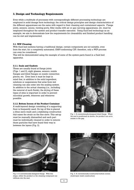
Fig. 1: A conventionally-designed blind flange. When<br />
the seal is positioned as shown, the product can accumulate<br />
in the gap.<br />
Fig. 3: A conventionally-constructed bottom screen<br />
(multi-layer mesh construction)