No. 30 - Glatt
No. 30 - Glatt
No. 30 - Glatt

You also want an ePaper? Increase the reach of your titles
YUMPU automatically turns print PDFs into web optimized ePapers that Google loves.
International<br />
<strong>No</strong>. <strong>30</strong> · December 2010<br />
Times<br />
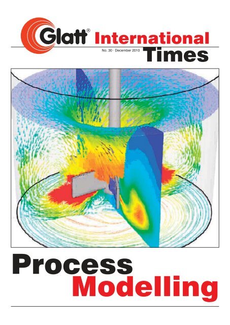
Process<br />
Modelling
Use of computational fluid dynamics for analysis<br />
of pharmaceutical equipment<br />
By Rok Šibanc, Rok Dreu, Stane Srčič<br />
Department of Pharmaceutical Technology, Faculty of Pharmacy, University of Ljubljana, Aškerčeva 7, 1000 Ljubljana, Slovenia<br />
Abstract: Computational fluid dynamics (CFD) uses numerical<br />
methods and physical models to analyze and solve various problems<br />
involving fluid flow, heat transfer, mass transfer, and chemical<br />
reactions. CFD modeling is used to optimize various process parameters,<br />
increase understanding of the processes, and obtain information<br />
regarding various process values that could not<br />
otherwise be measured or are difficult to measure.<br />
Keywords: Computational fluid dynamics, CFD, technological<br />
processes, pharmaceutical equipment<br />
1 Introduction<br />
Improving computing power has made computer simulations faster<br />
and more accurate, and therefore very useful for equipment and<br />
process development. Computer simulations are used in various<br />
fields, particularly the pharmaceutical industry. Moore’s Law describes<br />
the improvements in computing power, stating that the<br />
number of transistors per integrated circuit is doubling every 18<br />
months [1]. This increase in performance is also true for the fastest<br />
supercomputers on the top500.org list [2].<br />
One of the most commonly used computer simulation tools is computational<br />
fluid dynamics (CFD), which is mainly used for fluid flow<br />
analysis. It is used to analyze and solve various fluid flow problems<br />
in aerodynamics, hydrodynamics, electronics, the chemical industry,<br />
the food industry, the pharmaceutical industry, and many others<br />
2<br />
List of contents<br />
Use of computational fluid dynamics for<br />
analysis of pharmaceutical equipment 2<br />
Enteric coating of pharmaceutical products 8<br />
page<br />
Fluidised bed granule coating: Case studies<br />
of top and bottom spray coating 10<br />
Modern Pharmaceutical Process 13<br />
Pharmatronic at the ILMAC exhibition 20<br />
Pharmatronic:<br />
25th anniversary celebration 20<br />
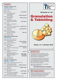
Forthcoming Events 22<br />
TTC Workshop <strong>No</strong>. 162: Pan Coating 23<br />
TTC Technology Workshops in 2011 24<br />
Published by:<br />
GLATT INTERNATIONAL<br />
79589 Binzen, Germany<br />
Ph: + 49 (0) 76 21 / 664 319<br />
Fax: + 49 (0) 76 21 / 16 799 200<br />
E-Mail: bianca.nowak@glatt.com<br />
Website: www.glatt.com<br />
Editor: Klaus Eichler<br />
Production: Bianca <strong>No</strong>wak<br />
[3]. Much of the published CFD research was done for the food industry,<br />
using very similar equipment to that used in pharmaceutical<br />
research. This means that many of the rules and models developed<br />
for CFD simulations of food industry equipment can be also applied<br />
to pharmaceutical research and development [4] and industrial<br />
scale production as well. In the last few years, CFD simulations<br />
have become more and more popular, but there have been few articles<br />
reviewing the use of CFD in pharmaceutical research. One<br />
of these, published by Kremer and Hancock, analyzed process<br />
simulations in the pharmaceutical industry and noted CFD as being<br />
a very promising modeling approach [5].<br />
2 Computational fluid dynamics<br />
2.1 History<br />
It is known that even the ancient Greeks were fascinated by various<br />
flow dynamics, particularly water and air flow. Their flow studies,<br />
however, were more oriented towards philosophy than science. In<br />
that time, Heraclitus made one of the best-known postulates about<br />
water flow (ca. 450 BCE): Ta Panta rhei (Everything flows). Around<br />
200 years later, Archimedes developed the basic principles of static<br />
mechanics and hydrostatics and developed methods for the measurement<br />
of density and volume. This science was further developed<br />
by the Romans in terms of the development of aqueducts,<br />
canals, harbors, and bathhouses. After the Romans, fluid flow was<br />
not taken up again until the time of Leonardo da Vinci, who was<br />
one of the first to study fluid flow. He made accurate qualitative descriptions<br />
of many different water phenomena. Newton followed<br />
da Vinci in the analysis of fluid flow and other phenomena. His contributions<br />
to the field were his well-known second law (F = ma),<br />
the concept of Newtonian viscosity, and the principle of reciprocity,<br />
which states that the force exerted by a fluid on an object equals<br />
the change of momentum of this fluid.<br />
Daniel Bernouli and Leonhard Euler made significant contributions<br />
to the field of fluid dynamics in the 18th and 19th centuries. Euler<br />
suggested equations for the conservation of mass and momentum<br />
for inviscid fluid. Claude Louis Marie Henry Navier and George<br />
Gabriel Stokes made another very significant contribution to the<br />
science of fluid flow. In the 19th century, they added the effect of<br />
viscous transport to the Euler equations and established the famous<br />
Navier-Stokes equation. This equation is a basis for all computational<br />
fluid dynamics. These equations are difficult to adapt to<br />
real-life problems but gained greater practical usefulness with the<br />
advent of modern computer technology between 1960 and 1970<br />
[6].<br />
In 1910, Luis Fry Richardson was the first to numerically solve the<br />
Navier-Stokes equations. He was trying to predict weather behavior,<br />
but his predictions were not useful due to their inaccuracy. The<br />
calculations took a long time to work out, as they were performed<br />
by hand. The first successful calculations of low velocity fluid flow<br />
past circular cylinders were performed by Thom [7]. The Japanese<br />
scientist Mitutosi Kawaguti was occupied 20 hours per week for 18<br />
months calculating flow around a cylinder using only a mechanical<br />
calculator. After 1960, a theoretical division of NASA in Los Alamos<br />
made a significant contribution by creating the commonly used kepsilon<br />
turbulence model. CFD codes were further developed at<br />
the Imperial College in London with the creation of the SIMPLE algorithm,<br />
which is now used in modern CFD codes. Another important<br />
milestone in CFD development came with the publication of<br />
Times <strong>No</strong>. <strong>30</strong> · December 2010
Patankar’s book Numerical Heat Transfer and Fluid Flow. In the<br />
early 1980s, many commercial codes became available and were<br />
first used by the aerospace industry, later the automobile industry,<br />
and then others [6].<br />
2.2 What is computational fluid dynamics?<br />
The physics of any fluid flow can be described by three fundamental<br />
principles: conservation of mass, conservation of energy, and<br />
F=ma (Newton’s second law). These principles can be expressed<br />
with mathematical equations- in the case of fluid flows they are usually<br />
in the form of differential equations. Computational fluid dynamics<br />
uses numerical algorithms to solve these equations in<br />
order to obtain numerical rather than analytical descriptions of the<br />
fluid flow. CFD calculations are computationally intensive because<br />
they perform millions of number operations and have therefore<br />
gained practical use only with the advent of modern computers.<br />
With increasing computer speed one can perform faster and more<br />
accurate CFD simulations. The use of supercomputers in CFD is<br />
therefore quite common [8].<br />
Differential equations that are used in computational fluid dynamics<br />
are:<br />
1. The continuity equation<br />
∂ρ<br />
∂t<br />
2. Momentum equation (Navier-Stokes equation)<br />
∂<br />
∂t<br />
where is static pressure, is gravitational force and is other<br />
forces, for example forces in porous zones. The stress tensor τ is<br />
2<br />
defined as vv v I , where is viscos-<br />
3<br />
ity and is unit tensor.<br />
T<br />
μ μ<br />
� =<br />
The momentum equation is derived from Newton’s second law<br />
�<br />
( amF<br />
). The equation describes two types of forces that act on<br />
a volume: the first are long acting, such as gravitational force, and<br />
the second are those that act on the surface of the volume. These<br />
forces are due to viscosity and pressure differences in the surrounding<br />
fluid [8, 9].<br />
3. Energy equation<br />
∂<br />
ρ<br />
∂t<br />
jj ( τ eff )) h<br />
j<br />
where k eff is effective heat conductivity and Jj is the diffusion flux<br />
of component . The first three terms on the right side of equation<br />
describe energy transfer due to conduction, diffusion, and loss of<br />
energy due to viscosity. represents heat that is released or consumed<br />
during the chemical reactions.<br />
�<br />
j<br />
Sh<br />
methods used are the finite difference and finite volume method.<br />
The finite volume method is used in most commercial and opensource<br />
CFD packages. The main principle of both methods is that<br />
the derivatives in differential equations are expressed as differences.<br />
Using the finite volume method, the domain is discretized<br />
into computational cells for which a system of equations is written<br />
and iteratively solved [8, 9].<br />
CFD simulations are used in single-phase flows (e.g., flow of gas)<br />
as well as in the analysis of multiphase flows (e.g., flow of particles<br />
in gas or fluid), which are common in many pharmaceutical<br />
processes. Multiphase simulations use additional equations for additional<br />
phases and consume more computational resources compared<br />
to the single-phase simulations. Common models used in<br />
multiphase flow modeling are Volume of Fluid (VOF), Mixture and<br />
Eulerian (Euler-Euler), and the coupled Eulerian Langrangian<br />
model.<br />
There are few commercial CFD packages available and the most<br />
commonly used are Fluent (Ansys), CFX (Ansys), and Fire (AVL).<br />
There are also many open-source CFD packages, the most popular<br />
being OpenFOAM, a package supported by OpenCFD [10, 11].<br />
2.3 Basic procedure for CFD simulation<br />
Before each CFD simulation, one must define the modeling goals,<br />
decide what physical models will be used, determine the domain<br />
of simulation, and consider the boundary conditions for the studied<br />
domain. The CFD simulation procedure is divided into three separate<br />
steps: i) creation of the computational model and grid, ii)<br />
model selection, and iii) calculation and post-processing of the results<br />
[9].<br />
2.3.1 Creation of the computational model and mesh<br />
For creation of the computational model (Figure 1) and computa-<br />
� �� � �<br />
ρρ)(<br />
)()(<br />
−∇=⋅ pv ρτ<br />
++⋅ ∇ Fg +<br />
vv<br />
∇+<br />
ρ g �<br />
F �<br />
I<br />
�<br />
ρv<br />
=⋅ 0)( ∇+<br />
ρ v �<br />
where is the density of the fluid and is the velocity of the fluid.<br />
This equation is based upon the law of conservation of mass and<br />
states that the change of mass in a volume over time is equal to<br />
the mass flow through the surface of this volume [8, 9].<br />
tional mesh it is important to determine possible model simplifica-<br />
tions because they can greatly reduce the calculation time. The<br />
computational mesh (Figure 2) is the base for numerically solving<br />
transport equations. When designing the computational mesh, the<br />
complexity of the flow and the total number of computational cells<br />
���<br />
τ )[ ⋅ ])(<br />
∇−∇+∇=<br />
(<br />
must be considered. More cells mean a more accurate solution,<br />
but also more memory and more computational power and time<br />
required for the calculation [9].<br />
2.3.2 Physical model selection and calculation<br />
When choosing physical models we are limited by these models’<br />
complexity and speed of calculation on the one hand and the accuracy<br />
and appropriate selection of these models on the other. For<br />
example, when modeling laminar fluid flow, turbulent models are<br />
�<br />
( ρ )) ()(<br />
⋅∇+ ( + ⋅∇= eff ∇ TkpEvE<br />
� �<br />
+⋅+−<br />
SvJ h<br />
∑<br />
The equation is derived from the first law of thermodynamics and<br />
describes the energy change due to heat flux and work done by<br />
the various acting forces [8, 9].<br />
Numerical methods are used because, in general, analytical solutions<br />
to these equations are not known. In this case, the two main Figure 1: 3D model of Wurster chamber nozzle<br />
Times <strong>No</strong>. <strong>30</strong> · December 2010<br />
3
Figure 2: 2D computational mesh of Wurster chamber<br />
unnecessary and would only increase the calculation time. The<br />
properties of the simulated fluid, such as temperature and viscosity,<br />
all boundary conditions (e.g., fluidizing air mass flow), and all initial<br />
conditions (e.g., volume fraction of pellets) must be set prior to the<br />
calculations. Numerical algorithms can solve all equations using<br />
iteration until convergence criteria are met. Calculations can take<br />
anywhere from a few minutes for simple geometries with basic<br />
models up to a few months for complex systems. Calculations that<br />
take longer than one month are generally impractical and rarely<br />
used [9].<br />
2.3.3 Post-processing of simulation results<br />
Numerical simulation results can be represented in numerical or<br />
graphical form. The graphical form (Figure 3) can be, for example,<br />
a vector field of a variable such as air velocity at a certain plane,<br />
colored pressure contours, or others [12]. The value of a variable<br />
is represented in color, most commonly using a blue-green-red<br />
color scale, where blue represents the lowest value of a particular<br />
variable and red the highest value. Data can be exported for any<br />
4<br />
Iso-surface<br />
Velocity vectors<br />
Pathlines<br />
Contours<br />
Figure 3: Example of the graphical presentation of simulation results [12].<br />
variable along a certain line of interest and then represented in the<br />
form of an XY plot (Figure 4). Average, minimum, and/or maximum<br />
values can be reported for selected domains. Mass and volume<br />
flow through the selected surfaces can be calculated as well. Fluid<br />
flow is often represented using pathways colored according to certain<br />
variables (e.g., components of velocity, pressure, temperature).<br />
An important part of post-processing is validation of the<br />
solution to check its correctness and to check the validity of selected<br />
models. In order to obtain more accurate simulation results,<br />
we can refine the computational mesh, use more complex models,<br />
and redo the calculations. Using a validated model, we are able to<br />
check how the system behaves using different boundary conditions<br />
and different fluid properties [9].<br />
Velocity Magnitude (air) (m/s)<br />
22.0<br />
20.0<br />
18.0<br />
16.0<br />
14.0<br />
12.0<br />
10.0<br />
8.0<br />
6.0<br />
4.0<br />
2.0<br />
0.0<br />
0 5 10 15 20<br />
Position (mm)<br />
25 <strong>30</strong> 35 40<br />
Figure 4: Example of an XY plot showing the air velocity profile inside the Wurster<br />
draft tube, where 0 represents the center of the draft tube.<br />
3 Some examples of CFD process simulations<br />
using pharmaceutical equipment<br />
Ansys (producer of the two largest commercial CFD packages)<br />
states that their software can be widely applied in the pharmaceutical<br />
industry. In their promotional material, they promote the use<br />
of CFD in drug production, analysis of pharmaceutical processes,<br />
and in studies of drug delivery systems, packaging, and transport.<br />
They also point out that CFD process simulations are in accordance<br />
with the FDA’s QbD guidelines that promote process understanding.<br />
Studies of chemical reactions in reactors, crystallization,<br />
nozzle sprays, particle movement in a Wurster fluid-bed, mixing,<br />
segregation, and others have been performed using Ansys software.<br />
Many studies were conducted in the areas of delivery systems<br />
and medical devices such as coronary stents, ophthalmic<br />
drug delivery systems, and inhalers. An important aspect of CFD<br />
research in the pharmaceutical and medical fields is the studies of<br />
various pathophysiological states. Ansys states that half of the<br />
leading pharmaceutical companies use CFD software [13–15].<br />
3.1 Mixers<br />
Kay et al. have been studying new equipment for powder milling<br />
and mixing using CFD. Experimental validation for milling was performed<br />
using lactose particles and blending experiments were conducted<br />
using lactose and NaCl. An important parameter of the<br />
milling device was the amount of airflow used for particle acceleration,<br />
collision power, and consequent milling (jet-mill). The simulations<br />
detected dead zones in the chamber, which were later<br />
confirmed by the experiments [16].<br />
Times <strong>No</strong>. <strong>30</strong> · December 2010
2.00e+00<br />
1.90e+00<br />
1.80e+00<br />
1.70e+00<br />
1.60e+00<br />
1.50e+00<br />
1.40e+00<br />
1.<strong>30</strong>e+00<br />
1.20e+00<br />
1.11e+00<br />
1.01e+00<br />
9.07e−01<br />
8.07e−01<br />
7.08e−01<br />
6.09e−01<br />
5.09e−01<br />
4.10e−01<br />
3.00e−01<br />
2.11e−01<br />
1.12e−01<br />
Y X<br />
1.23e−02 Z<br />
Figure 5: Particle velocity (scale on the left, m/s) in a high-shear mixer [17].<br />
Another CFD simulation conducted by Darelius et al. studied particle<br />
movement in a high-shear mixer (Figure 5). The authors argued<br />
that using this type of simulation improves understanding of<br />
the granulation process and supports the development of process<br />
models. The simulation was validated using a particle velocity profile<br />
obtained using a high-speed camera on the wall of the mixer.<br />
The experimental data were not in complete accordance with the<br />
simulation. It was concluded that the two-phase models that describe<br />
particle interactions must be developed further [17].<br />
3.2 Fluid-bed equipment<br />
CFD simulation coupled with a population balance model was<br />
used to examine granule growth during granulation in a fluid-bed<br />
chamber. From experimental data, the authors concluded that the<br />
principal parameter that affects granule formation is the roughness<br />
of the starting material; in other words, the active pharmaceutical<br />
ingredients (APIs) and excipients. They constructed a population<br />
balance model with one parameter and used it to measure the<br />
granule growth rate [18].<br />
2.00<br />
1.90<br />
1.80<br />
1.70<br />
1.60<br />
1.50<br />
1.40<br />
1.<strong>30</strong><br />
1.20<br />
1.10<br />
1.00<br />
0.90<br />
0.80<br />
0.70<br />
0.60<br />
0.50<br />
0.40<br />
0.<strong>30</strong><br />
0.20<br />
0.10<br />
0.00<br />
Figure 6: Velocity vectors and volume fraction contours of pellets at two different<br />
time intervals (difference of 0.2 seconds) in a novel fluid-bed device [20]<br />
150.01<br />
142.51<br />
135.01<br />
127.51<br />
120.01<br />
112.01<br />
105.01<br />
97.50<br />
90.00<br />
82.50<br />
75.00<br />
67.50<br />
60.00<br />
52.50<br />
45.00<br />
37.50<br />
<strong>30</strong>.00<br />
22.50<br />
15.00<br />
7.50<br />
0.00 Y X<br />
Z Y<br />
Figure 7: Air pathways in a spray nozzle colored according to velocity (m/s)<br />
25.00<br />
23.75<br />
22.50<br />
21.25<br />
20.00<br />
18.75<br />
17.50<br />
16.25<br />
15.00<br />
13.75<br />
12.50<br />
11.25<br />
10.00<br />
8.75<br />
7.50<br />
6.25<br />
5.00<br />
3.75<br />
2.50<br />
1.25<br />
0.00<br />
Y<br />
X<br />
Z<br />
Figure 8: Air pathways and their velocities (m/s) in a fluid-bed coater<br />
Studies of fluidizing air distribution in a Wurster chamber have also<br />
been performed. Experimental data was used to determine the coefficients<br />
of permeability of the distribution plate and that parameter<br />
was used in simulations analyzing the homogeneity of air flow. Simulation<br />
results were confirmed using chamber wall temperature<br />
measurements and comparing those to the simulation predictions.<br />
The authors concluded that this type of simulation can be used to<br />
test construction changes in order to improve the performance of<br />
the chamber [19].<br />
Times <strong>No</strong>. <strong>30</strong> · December 2010<br />
5
CFD simulations are becoming increasingly important because<br />
they are more and more commonly used in the development of<br />
new equipment. <strong>Glatt</strong> used CFD simulation to analyze their new<br />
ProCell technology, which is used for granulation and particle coating.<br />
They used the two-phase Euler approach to observe particle<br />
movement within the chamber (Figure 6). The simulation was validated<br />
by pressure drop measurements and by visual analysis of<br />
a model device. CFD simulations are useful for determination of<br />
the device’s process parameters [20].<br />
The main purpose of CFD simulations for our research group is to<br />
analyze the fluid-bed coating process. Our 2D axisymmetric and<br />
3D computer meshes were based upon the real geometry of<br />
GPCG-1. The 2D mesh had far fewer computational cells compared<br />
to the 3D (about 50,000 compared to 1 million) and was<br />
used for two-phase simulations. The common method for performing<br />
the simulations is to start with single-phase simulations; in our<br />
case a simulation of fluidizing and atomizing air flow only. We conducted<br />
a simulation of atomizing air flow through a spray nozzle<br />
(Figure 7) and observed its effect on the hydrodynamics in the<br />
chamber by analyzing the pressure field and air velocity values<br />
(Figure 8).<br />
The next step was two-phase flow modeling for example of the particles<br />
(pellets) in the air. Figure 9 gives a snapshot of the simulation<br />
data at a certain point and shows the particle distribution inside the<br />
chamber. The color scale represents the particle volume fraction,<br />
where dark blue represents the presence of air only and the red<br />
represents a particle concentration of <strong>30</strong>% or higher. These simulations<br />
have been validated and used for the study of Wurster gaps,<br />
air velocities, the effect of a spray nozzle, amounts of materials in<br />
a chamber, and other process parameters that affect the uniformity<br />
of particle coating and process efficiency.<br />
6<br />
0.<strong>30</strong><br />
0.29<br />
0.27<br />
0.25<br />
0.24<br />
0.23<br />
0.21<br />
0.20<br />
0.18<br />
0.17<br />
0.15<br />
0.14<br />
0.12<br />
0.11<br />
0.09<br />
0.08<br />
0.06<br />
0.05<br />
0.03<br />
0.02<br />
0.00<br />
Figure 9: Particle distribution in a fluid-bed coater<br />
3.3 Spray drying<br />
Spray drying is a common process in the pharmaceutical industry,<br />
but it is even more common in the food industry. This is why there<br />
are many publications on the topic. The basic principles of spray<br />
drying are the same for both industries. Ansys argues that their<br />
CFD software can be used to analyze spray nozzles and cyclone<br />
performance [13].<br />
CFD can be used to analyze various spray-dryer designs such as<br />
the performance of wide or elongated drying chambers. Simulations<br />
can search for optimization in regard to material loss on the<br />
chamber walls during operation. It has been shown and confirmed<br />
that one of the main parameters in spray drying is droplet size.<br />
Droplets of sizes below 5 μm completely follow the air pathways<br />
while droplets of sizes between 5 and <strong>30</strong> μm decrease in size during<br />
the drying procedure and then start to follow the air flow.<br />
Droplets of over <strong>30</strong> μm, however, have the tendency to hit and stick<br />
to the walls due to the geometry of the chamber studied in this<br />
case. Simulations can predict the area where the highest amount<br />
of material will be deposited and this information can be used for<br />
simulation validation. The validation of spray-drying simulation has<br />
been performed with experiments using an NaCl water solution.<br />
Using simulations, the effect of inlet drying air angle was found to<br />
be an important factor for flow pattern changes and consequently<br />
for drying changes. Research done to analyze the effect of the<br />
spray nozzle on drying performance was given much attention<br />
[21].<br />
Fletcher et al. [22] found that 3D transient simulation should be<br />
used for spray-dry modeling. They found that it is able to predict<br />
the formation of unstable flows, flows which result in a significant<br />
wall deposition. The authors argued that spray-drying simulation<br />
should be performed using more complex turbulence models such<br />
as Reynolds Averaged Navier-Stokes (RANS) or Large Eddy Simulation<br />
(LES). In cases where the k-epsilon turbulence model is<br />
used it should be in combination with a finer computational mesh<br />
and shorter time intervals.<br />
Langrish [23] describes various levels of spray-dryer modeling. The<br />
robust approach considers only mass and heat balance and CFD<br />
is considered to be the most detailed method of modeling. The<br />
study considers CFD as an appropriate tool for analysis of material<br />
deposition and new spray-dryer designs.<br />
3.4 Reactors<br />
Reactors are commonly used in the first stages of medicine production,<br />
for example in the production of APIs. They are used in<br />
chemical reactions, crystallizations, and in the production of<br />
biotech APIs. Mixers and reactors are similar from a construction<br />
point of view and are used in the preparation of solutions, emulsions,<br />
and suspensions that represent either final dosage form<br />
preparation or a step in their preparation [13, 14].<br />
Crystallization of APIs is an important phase in the pharmaceutical<br />
development process because crystal size and shape might have<br />
a significant effect on various processes. The behavior of variously<br />
sized particles in a crystallization chamber has been studied. Particles<br />
with sizes between 50 and 900 μm were divided into six size<br />
fractions and spread homogenously in the chamber at the beginning<br />
of the simulation. The speed of the impeller and the particle<br />
size were found to significantly affect particle distribution in the device.<br />
Simulations showed that additional construction elements<br />
could diminish the sedimentation of the largest particles [24]. Crystallization<br />
simulations can be used to study shear stress and its effect<br />
upon particle growth and damage. Additional models in CFD<br />
simulations can be used to study the crystal growth and assess<br />
their final size [13].<br />
Times <strong>No</strong>. <strong>30</strong> · December 2010
CFD simulations represent a valuable tool in the analysis of<br />
biotechnological production. The distribution of air bubbles, dissolved<br />
gases, and other components in solutions can be predicted<br />
and controlled. CFD seems to be applicable for optimizing a reactor’s<br />
operation and in making scale-up processing more efficient<br />
[13, 25].<br />
4 Conclusion<br />
In this article, some examples are given of CFD use in the pharmaceutical<br />
industry. There are, however, many other potential areas<br />
of CFD usage: HVAC (Heating, Ventilating, and Air Conditioning),<br />
the design of pilot space clean rooms [26], safety dynamics such<br />
as preventing dust explosions [27], in environmental sciences, and<br />
for water quality control. CFD simulations can also support the understanding<br />
of basic human physiology (e.g., gastrointestinal tract,<br />
heart, blood vessels), something that is necessary for designing<br />
medicinal products [13]. Drug delivery and drug release studies<br />
have also been supported by CFD simulation by improving the understanding<br />
of the process and the hydrodynamics of the environment<br />
[28, 29]. In vivo experimentation studies have also been<br />
conducted using CFD. These results can help in choosing the appropriate<br />
tests for the in vitro/in vivo correlation [<strong>30</strong>].<br />
CFD simulations alone have a limited ability to model real systems.<br />
This is the reason that they are coupled with other simulation methods.<br />
Some of the models that are coupled with CFD are the discrete<br />
element method (DEM) and finite element method (FEM).<br />
These couplings require even more processing power, so they<br />
have only been used in the last ten years. Application of such a<br />
simulation approach is useful for pneumatic transport systems and<br />
fluid-bed systems [31] or for the study of air-particle interactions in<br />
tableting machines [32]. Further development of computer hardware<br />
and simulation models will enable the extensive simulation of<br />
drug delivery and drug release applications [33] and the simulation<br />
of industrial processes with millions of particles in the air flow [34],<br />
something that is still not possible today.<br />
It is important to note that simulations are never to be used alone;<br />
that is, without any experiment or model development. All three aspects<br />
of research – modeling, simulation, and experimental validation<br />
– should be used in conjunction and only this can provide<br />
better process understanding and contribute to process efficiency<br />
and the development of products of increased quality. Better understanding<br />
of pharmaceutical processes is part of the FDA’s<br />
paradigm and is expressed in the QbD guidelines [35].<br />
Literature<br />
1. Moore’s Law: Made real by Intel® innovation. http://www.intel.com/technology/mooreslaw/<br />
(17. 2. 2010).<br />
2. Performance Development | TOP500 Supercomputing Sites. http://www.<br />
top500.org/lists/2009/11/performance_development (17. 2. 2010).<br />
3. Versteeg HK, Malalasekera W. An introduction to computational fluid dynamics.<br />
Pearson Education, 2007.<br />
4. <strong>No</strong>rton T, Sun D. Computational fluid dynamics (CFD) - an effective and efficient<br />
design and analysis tool for the food industry: A review. Trends Food<br />
Sci Tech 2006; 17 (11): 600–620.<br />
5. Kremer D, Hancock B. Process simulation in the pharmaceutical industry:<br />
A review of some basic physical models. J Pharm Sci 2006; 95 (3): 517–<br />
529.<br />
6. A Brief History of Computational Fluid Dynamics (CFD) from Fluent.<br />
http://www.fluent.com/about/cfdhistory.htm (17. 2. 2010).<br />
7. Thom A. The Flow Past Circular Cylinders at Low Speeds. Proc Royal Society<br />
1933; A141: 651–669.<br />
8. Wendt JF. Computational Fluid Dynamics. Springer, 2009.<br />
9. Dokumentacija programskega pakega Fluent 6.3. Ansys, 2006.<br />
10. OpenFOAM® - The Open Source Computational Fluid Dynamics (CFD)<br />
Toolbox. http://www.openfoam.com/ (5. 7. 2010).<br />
11. CFD Online Discussion Forums. http://www.cfd-online.com/Forums/ (5. 7.<br />
2010).<br />
12. Kinnear D, Atherton M, Collins M, et al. Colour in visualisation for computational<br />
fluid dynamics. Optics & Laser Tech 2006; 38 (4–6): 286–291.<br />
13. Ansys Webinar: Pharmaceutical Process Development Using ANSYS CFD<br />
Simulation Technologies.<br />
14. Flow Modeling Solutions for the Biomedical, Healthcare & Pharmaceutical<br />
Industries from Fluent.<br />
http://www.fluent.com/solutions/biomedical/index.htm (4. 3. 2010).<br />
15. Fluent News, Spring 2004. http://www.fluent.com/about/news/newsletters/04v13i1/04v13i1<br />
(1. 3. 2010).<br />
16. Kay GR, Staniforth JN, Tobyn MJ, et al. Design of a fluid energy single vessel<br />
powder processor for pharmaceutical use. Int J Pharm 1999; 181 (2): 243–<br />
254.<br />
17. Darelius A, Rasmuson A, van Wachem B, et al. CFD simulation of the high<br />
shear mixing process using kinetic theory of granular flow and frictional<br />
stress models. Chem Eng Sci 2008; 63 (8): 2188–2197.<br />
18. Rajniak P, Stepanek F, Dhanasekharan K, et al. A combined experimental<br />
and computational study of wet granulation in a Wurster fluid bed granulator.<br />
Powder Technol 2009; 189 (2): 190–201.<br />
19. Depypere F, Pieters JG, Dewettinck K. CFD analysis of air distribution in fluidized<br />
bed equipment. Powder Technol 2004; 145 (3): 176–189.<br />
20. Jacob M. ProCell technology: Modelling and application. Powder Technol<br />
2009; 189 (2): 332–342.<br />
21. Langrish TAG, Fletcher DF. Spray drying of food ingredients and applications<br />
of CFD in spray drying. Chem Eng Process 2001; 40 (4): 345–354.<br />
22. Fletcher D, Guo B, Harvie D, et al. What is important in the simulation of<br />
spray dryer performance and how do current CFD models perform? Appl<br />
Math Model 2006; <strong>30</strong> (11): 1281–1292.<br />
23. Langrish TAG. Multi-scale mathematical modeling of spray dryers. J Food<br />
Eng 2009; 93 (2): 218–228.<br />
24. Sha Z, Oinas P, Louhi-Kultanen M, et al. Application of CFD simulation to<br />
suspension crystallization-factors affecting size-dependent classification.<br />
Powder Technol 2001; 121 (1): 20–25.<br />
25. Gad SC. Handbook of pharmaceutical biotechnology. John Wiley and Sons,<br />
2007.<br />
26. Rouaud O, Havet M. Computation of the airflow in a pilot scale clean room<br />
using K-epsilon turbulence models. Int J Pharm 2002; 25 (3): 351–361.<br />
27. Kosinski P, Hoffmann AC. Dust explosions in connected vessels: Mathematical<br />
modelling. Powder Technol 2005; 155 (2): 108–116.<br />
28. Arifin DY, Lee LY, Wang C. Mathematical modeling and simulation of drug<br />
release from microspheres: Implications to drug delivery systems. Adv Drug<br />
Deliver Rev 2006; 58 (12–13): 1274–1325.<br />
29. Baxter JL, Kukura J, Muzzio FJ. Hydrodynamics-induced variability in the<br />
USP apparatus II dissolution test. Int J Pharm 2005; 292 (1–2): 17–28.<br />
<strong>30</strong>. D’Arcy DM, Healy AM, Corrigan OI. Towards determining appropriate hydrodynamic<br />
conditions for in vitro in vivo correlations using computational<br />
fluid dynamics. Eur J Pharm Sci 2009; 37 (3–4): 291–299.<br />
31. Chu K, Yu A. Numerical simulation of complex particle-fluid flows. Powder<br />
Technol 2008; 179 (3): 104–114.<br />
32. Guo Y, Kafui KD, Wu C, et al. A coupled DEM/CFD analysis of the effect of<br />
air on powder flow during die filling. AIChE J 2009; 55 (1): 49–62.<br />
33. Sugano K. Theoretical comparison of hydrodynamic diffusion layer models<br />
used for dissolution simulation in drug discovery and development. Int J<br />
Pharm 2008; 363 (1–2): 73–77.<br />
34. Turton R. Challenges in the modeling and prediction of coating of pharmaceutical<br />
dosage forms. Powder Technol 2008; 181 (2): 186–194.<br />
35. Center for Drug Evaluation and Research. Guidance for Industry PAT – A<br />
Framework for Innovative Pharmaceutical Development, Manufacturing, and<br />
Quality Assurance. http://www.fda.gov/downloads/Drugs/GuidanceComplianceRegulatoryInformation/Guidances/UCM070<strong>30</strong>5.pdf<br />
(10 March 2010).<br />
Times <strong>No</strong>. <strong>30</strong> · December 2010<br />
7
Enteric coating of pharmaceutical products<br />
By Krisanin Chansanroj<br />
Enteric coating formulations<br />
Enteric coating is aimed to prevent the formulations from gastric<br />
fluid in the stomach and release the drug component in the intestinal<br />
region. Based on this approach, enteric coating is suitably applied<br />
for drugs which cause gastric irritation or are deteriorated by<br />
the gastric fluid or gastric enzyme.<br />
Enteric coating polymer<br />
With an acid-resistant property, enteric coating polymers generally<br />
possess free carboxylic acid groups on the polymer backbone.<br />
They are insoluble in acidic media but become deprotonated and<br />
dissolved in basic media at nearly neutral pH values (pH>5). Enteric<br />
coating polymers can be classified into 3 groups based on<br />
chemical compositions as listed below:<br />
Polymethacrylates<br />
Methacrylic acid/ethyl acrylate<br />
Cellulose esters<br />
Cellulose acetate phthalate (CAP)<br />
Cellulose acetate trimellitate (CAT)<br />
Hydroxypropylmethylcellulose acetate succinate<br />
(HPMCAS)<br />
Polyvinyl derivatives<br />
Polyvinyl acetate phthalate (PVAP)<br />
Solubility of the polymers depends on the number of carboxylic<br />
acid groups varied in the composition. Commercial enteric coating<br />
polymers are available as powder, aqueous dispersion and organic<br />
solution.<br />
Enteric coating formulations need special care of coating operation<br />
due to the constrain of drug release specified in the regulatory requirements.<br />
Enteric formulations should have less than 10% drug<br />
release after 2 hours in the acid stage. The completion of the drug<br />
release in the continuation testing in the buffer stage should take<br />
place within 45 min.<br />
Organic solution and aqueous dispersion<br />
Generally, enteric coating polymers dissolve well in organic solvents,<br />
giving a stable coating solution that facilitates faster coating<br />
processes due to easy evaporation of organic solvents. However,<br />
the practical use of organic solvents in pharmaceutical formulations<br />
has decreased since organic solvent residues in final products<br />
are restricted by the authorities. Flammability of organic<br />
solvents and their toxicity to operators, as well as their harmfulness<br />
to the environment are further reasons. These concerns encourage<br />
the use of aqueous dispersion systems with <strong>30</strong>-40% wt. dry polymer<br />
dispersed in water systems, assisted by surfactants. The last<br />
years efforts have been made to develop ready to use dispersions<br />
which include all auxiliary components such as plasticizers, opacifiers,<br />
and antifoaming agents.<br />
However, the film formation process based on organic solvents and<br />
aqueous dispersions is basically different. The polymer in the organic<br />
solutions undergoes sol to gel transitions during solvent<br />
evaporation whereas polymer particles in aqueous dispersions deposit<br />
layer by layer on the surfaces of the coating substrates. Whilst<br />
water evaporates, polymer particles approach each other, due to<br />
capillary force, and gradually fuse to a uniform layer [1]. Therefore<br />
the size of polymer particles in the dispersion could influence film<br />
formation. The smaller the particles are, the larger the contact area<br />
between the polymer particles becomes. This accelerates polymer<br />
coalescence [2]. By consequence a lower amount of dry polymer<br />
is required for the enteric protection [3].<br />
8<br />
Enteric coating based on aqueous dispersion systems has also<br />
some limitations. Coating processes take longer than with organic<br />
solvent systems as there is more energy required to evaporate<br />
water than for solvents. This could increase the deterioration of<br />
heat- and/or moisture-sensitive drugs during coating processes<br />
[3]. Furthermore, the aqueous dispersion systems are generally<br />
susceptible to coagulation because of a number of factors, such<br />
as additions of fine powder pigments or wetting agents, high shear<br />
gradients during mixing and pH change. Therefore, the preparation<br />
of coating dispersion needs careful operations following the directions<br />
for use suggested by the producer.<br />
Plasticizer<br />
Success of enteric coating efficiency mostly relies on the addition<br />
of plasticizers. Plasticizers are a group of auxiliary components that<br />
improve elasticity of the polymeric film which is generally rigid and<br />
breakable. Plasticizers reduce the minimum film forming temperature<br />
(MFFT) of the polymers, softening the polymeric film at lower<br />
temperature. This improves the spreadability of the polymer on the<br />
surface of the coating substrates and generates a smoother surface<br />
texture of the coating layer [3].<br />
The type of plasticizer should be selected carefully as it influences<br />
the film brittleness [4], compatibility with the coating substrates [5]<br />
and product stability [3, 5]. Hydrophilic plasticizer, triethyl citrate,<br />
is reported to improve the property of Eudragit L <strong>30</strong> D-55 film in<br />
the soft gelatin capsule formulations regardless of the type of filled<br />
liquid whereas hydrophobic plasticizer, tributyl citrate, gives satisfactory<br />
enteric protection only with hydrophobic filled liquid [5].<br />
The latter plasticizer could migrate to the hydrophobic filled liquid<br />
upon storage, resulting in the reduction of the enteric protection.<br />
Besides the plasticizer type, the amount of plasticizer is important<br />
for film flexibility. Insufficient amount of plasticizer causes the film<br />
blistering which could lead to a premature drug release in acidic<br />
media, as shown in Figure 1. However, high amount of plasticizer<br />
reduces the strength of the film and may accelerate the water uptake<br />
into the cores upon storage.<br />
A B C<br />
Fig. 1: Enteric coated tablets with insufficient plasticizer; (A) before dissolution<br />
test, (B) and (C) after dissolution test in the acid stage for 1 and 2 h, respectively.<br />
Subcoating<br />
The major concern in enteric coating formulations is a risk of premature<br />
drug release through the enteric coating film in acid media.<br />
This problem could be solved by an application of a subcoating<br />
layer where the coating substrates are subject to coating with a<br />
small amount of a soluble material, i.e., HPMC, amylopectin, prior<br />
to enteric coating. This thin film layer impedes water penetration<br />
through the cores and thus prevents the premature drug release.<br />
Subcoating is supportive in formulations which contain highly<br />
water-soluble drugs [6-8]. This is where premature drug release<br />
mostly occurres. On the contrary, subcoating could also enhance<br />
the release of acidic drugs in basic media. This causes a problem<br />
of acidic microenvironment at the interface between the core and<br />
the enteric film. The migration of diffused drug through the interface<br />
results in the delay of drug release in basic media [9].<br />
Times <strong>No</strong>. <strong>30</strong> · December 2010
Due to the restriction in the regulatory requirements, not only the<br />
prevention of premature drug release in acidic media should be<br />
taken into account, but also the accomplishment of rapid drug release<br />
in basic media. To cope with the latter constrain, a new concept<br />
of organic acids addition in coating substrates or subcoating<br />
layer is initiated in order to promote the basic microenvironment<br />
(pH 5-6) at the interface between the enteric film and the cores<br />
which could accelerate the polymer dissolution [6, 8, 10-11].<br />
Furthermore, the subcoating layer reduces surface roughness of<br />
the coating substrate and improves adhesion of the enteric film on<br />
the substrate surface. This generates a robust film formation where<br />
a lower amount of enteric coating polymer may be required for enteric<br />
protection [3].<br />
Coating operation<br />
Minimum film forming temperature (MFFT)<br />
Besides the knowledge of enteric coating liquids, the coating condition<br />
are important for coating efficiency. Since film formation requires<br />
the coalescence of the polymer particles on the coating<br />
substrates' surface, product temperature should be set to about<br />
the polymer's MFFT. This temperature characterizes each polymer.<br />
It can be influenced by the type and amount of plasticizers. For enteric<br />
coating processes based on aqueous dispersion systems,<br />
product temperature is usually set to a range of <strong>30</strong>-40°C, in practical<br />
operations.<br />
The effect of product temperature becomes troublesome in enteric<br />
coating due to the hydrophilicity of enteric coating polymers. They<br />
tend to become sticky under humid conditions. The agglomeration<br />
of coated particles most likely occurs when the temperature is set<br />
too low. This problem becomes crucial in the case of pellet formulations<br />
as the growth of sticky pellets takes place in a very short<br />
time which could ruin the whole batch if the coating conditions cannot<br />
be adjusted in time, see Figure 2.<br />
A B<br />
Fig. 2: Effect of low product temperature during coating process; (A) uncoated<br />
pellets, (B) coated pellets with agglomeration.<br />
A B<br />
Fig. 3: Effect of high product temperature during coating process; (A) orange<br />
peel surface, (B) air trapped under coating layer.<br />
On the other hand, if the product temperature is set too high, this<br />
accelerates the solvent/ aqueous evaporation, generating more viscous<br />
sprayed-liquid droplets which barely spread on the surface<br />
of the coating substrates. This leads to one kind of coating failure<br />
which is called 'orange peel appearance'. It results in an inconsistency<br />
of the coating layer. Furthermore, high temperature condition<br />
could accelerate the volume expansion of the air trapped under<br />
the coating layer, shown as the blow out of the film layer, see Figure<br />
3. High temperature and long time processing also accelerate the<br />
evaporation of some plasticizers, for example triethylcitrate, thus<br />
changing the enteric film property [3].<br />
Coating film distribution<br />
Coating uniformity is attributed to the distribution of sprayed liquid<br />
on the surface of the coating substrates. This correlates with the<br />
design of the equipment used. For example, in pan coating systems,<br />
pan speed has a significant influence on the quality of the<br />
film distribution through the mass variance of the moving tablets<br />
which determines the optimal amount of polymer for the enteric<br />
protection [12]. In Wurster-type fluid bed systems, the coating uniformity<br />
depends on the mass of coating substrates passing<br />
through the spray zone. it is influenced by inlet air volume, spray<br />
shape, flow pattern of the substrates and the gap between the<br />
Wurster partition and the air distributing plate [13-15]. The condition<br />
of low inlet air volume and low level of the partition tends to<br />
generate a dead zone, where the coating substrates cannot be uniformly<br />
coated [15].<br />
Curing process and storage condition<br />
Some types of enteric coating polymers, such as HPMCAS, require<br />
a special curing process at an elevated temperature and high relative<br />
humidity to induce the polymer coalescence [3, 16]. CAP and<br />
CAT coatings present instability of the film upon storage especially<br />
at high temperatures. This is due to the hydrolysis of ester groups<br />
followed by the formation of insoluble cellulose acetate. Furthermore,<br />
final products coated with aqueous dispersion systems tend<br />
to be sintered upon storage if hydrophilic plasticizers are incorporated<br />
[3].<br />
References<br />
1. Eckerseley S.T. and Rudin A., Mechanism of film formation from polymer latexes.<br />
J Coat Technol, 1990. 62: p. 89-100.<br />
2. Steward P.A., et al., An overview of polymer latex film formation and properties.<br />
Adv Colloid Interface Sci, 2000. 86(3): p. 195-267.<br />
3. Thoma K. and Bechtold K., Influence of aqueous coatings on the stability<br />
of enteric coated pellets and tablets. Eur J Pharm Biopharm, 1999. 47(1):<br />
p. 39-50.<br />
4. Gutiérrez-Rocca J. and McGinity J.W., Influence of water soluble and insoluble<br />
plasticizers on the physical and mechanical properties of acrylic resin<br />
copolymers. Int J Pharm, 1994. 103(3): p. 293-<strong>30</strong>1.<br />
5. Felton L.A., et al., Physical and enteric properties of soft gelatin capsules<br />
coated with eudragit® L <strong>30</strong> D-55. Int J Pharm, 1995. 113(1): p. 17-24.<br />
6. Bruce L.D., et al., Properties of enteric coated sodium valproate pellets. Int<br />
J Pharm, 2003. 264(1-2): p. 85-96.<br />
7. Guo H.X., et al., Amylopectin as a subcoating material improves the acidic<br />
resistance of enteric-coated pellets containing a freely soluble drug. Int J<br />
Pharm, 2002. 235(1-2): p. 79-86.<br />
8. Sauer D., et al., Influence of polymeric subcoats on the drug release properties<br />
of tablets powder-coated with pre-plasticized Eudragit® L 100-55. Int<br />
J Pharm, 2009. 367(1-2): p. 20-28.<br />
9. Crotts G., et al., Development of an enteric coating formulation and process<br />
for tablets primarily composed of a highly water-soluble, organic acid. Eur<br />
J Pharm Biopharm, 2001. 51(1): p. 71-76.<br />
10. Liu F., et al., A novel concept in enteric coating: A double-coating system<br />
providing rapid drug release in the proximal small intestine. J Control Release,<br />
2009. 133(2): p. 119-124.<br />
11. Liu F., et al., SEM/EDX and confocal microscopy analysis of novel and conventional<br />
enteric-coated systems. Int J Pharm, 2009. 369(1-2): p. 72-78.<br />
12. Tobiska S. and Kleinebudde P., Coating uniformity and coating efficiency in<br />
a Bohle Lab-Coaterusing oval tablets. Eur J Pharm Biopharm, 2003. 56(1):<br />
p. 3-9.<br />
13. Karlsson S., et al., Measurement of the particle movement in the fountain<br />
region of a Wurster type bed. Powder Technol, 2006. 165(1): p. 22-29.<br />
14. KuShaari K., et al., Monte Carlo simulations to determine coating uniformity<br />
in a Wurster fluidized bed coating process. Powder Technol, 2006. 166(2):<br />
p. 81-90.<br />
15. Shelukar S., et al., Identification and characterization of factors controlling<br />
tablet coating uniformity in a Wurster coating process. Powder Technol,<br />
2000. 110(1-2): p. 29-36.<br />
16. Siepmann F., et al., Aqueous HPMCAS coatings: Effects of formulation and<br />
processing parameters on drug release and mass transport mechanisms.<br />
Eur J Pharm Biopharm, 2006. 63(3): p. 262-269.<br />
Krisanin Chansanroj PhD, is currently a postdoctoral<br />
fellow at Industrial Pharmacy Research Group, Dep. of<br />
Pharmaceutical Sciences, University of Basel. Her present<br />
works involve enteric coating formulations using fluid<br />
bed systems and direct compacted matrix tablets.<br />
Times <strong>No</strong>. <strong>30</strong> · December 2010<br />
9
Fluidised bed granule coating:<br />
Case studies of top and bottom spray coating<br />
By Abdullah Alrashidi and Ei Leen Chan<br />
Granule coating, an essential technique used predominantly in the<br />
pharmaceutical, food and fertilizer industries, involves the application<br />
of a film or coating to solid particles [1]. Granules are coated<br />
for a number of reasons: to provide a barrier to oxidation, humidity,<br />
light or any other potential sources of degradation of the active<br />
principal, to improve the appearance, mask the taste or odours of<br />
products, to functionalise powder and to avoid caking phenomena<br />
during storage and transport [2]. A number of coating technologies<br />
are commercially available and could be generally divided into<br />
two categories: systems using mechanical agitation such as rotating<br />
drum and pan and those that use pneumatic mixing; for example<br />
fluidised beds and spouted beds. The fluidised bed is a widely<br />
used process in the production of coated granules, having been<br />
successfully used for coating solid particles such as pellets, granules<br />
and powder. During this process, granules are fluidised by hot<br />
air in which the coating solution is applied using a spraying nozzle.<br />
The nozzle could be positioned at either the top or bottom of the<br />
fluidised bed [1].<br />
The quality and functionality of the coated granule could be evaluated<br />
using various tests, one of which is the dissolution test. It is<br />
performed to determine the effect of coating on the rate of release<br />
of the active ingredient in a suitable (and usually physiologically<br />
relevant) media. Scanning electron microscopy (SEM) is another<br />
invaluable technique in this area of study and has improved the<br />
general understanding of the physical properties of coated granules<br />
[3]. Moreover, a few studies have made use of SEM to determine<br />
the thickness of deposited materials on coated granules [3,<br />
4].<br />
A number of studies have focused on the effect of different variables<br />
on the coating process by conducting coating experiments<br />
at bench scale using bottom spray or top spray methods [5, 6].<br />
The present study uses dissolution tests, coating content tests and<br />
SEM to evaluate the film coating applied to granules for different<br />
coating methods in a fluidised bed coater (ie: bottom and top spray<br />
methods).<br />
Figure 1: Top spray (left) and bottom spray (right) configurations for the fluidised bed coater [adapted from 7].<br />
10<br />
<strong>No</strong>zzle<br />
Distributor<br />
Plate<br />
Fluidising Air<br />
1. Top and bottom spray coated granules<br />
The granules were firstly prepared in a high-shear granulator (Romaco<br />
Roto Junior) using microcrystalline cellulose (MCC) and lactose<br />
M200 powders. The experiments were performed as follow:<br />
850g of MCC and 150g of lactose were added into the high-shear<br />
granulator for each batch, the granulation powder was premixed<br />
for 2 minutes by running the impeller at 250 rpm. A binding solution<br />
of 1kg of water with 10g of sodium chloride (NaCl) was then poured<br />
into the mixer with the binder addition time kept constant at 1<br />
minute for all batches. NaCl was added for the dissolution tests<br />
carried out subsequently (Section 2.1). The mixture was then allowed<br />
to granulate for 10 minutes. The granules were dried in the<br />
vacuum oven for 4 hours at a temperature of 40 °C and subsequently<br />
sieved into different size ranges (180, 360, 655 and 1090<br />
microns).<br />
A fluidised bed coater (<strong>Glatt</strong> WSG/GPCG-3), with both top-spray<br />
and bottom-spray (Figure 1) configurations was used to spray the<br />
coating solution onto the surface of the granules. Hydroxypropyl<br />
methylcellulose, HPMC (Pharmacoat 603W, Shin-Etsu Chemical<br />
Co. Ltd) solution was used as the coating agent which was mixed<br />
with red dye for analysis purposes (Section 2.2). For the top-spray<br />
configuration, coating liquid was sprayed from above through a<br />
nozzle against the fluidising air flow while a draft tube (Wurster<br />
tube) was used to assist an upwards spray of the coating agent for<br />
the bottom-spray method. 250g batches of granules were allowed<br />
to fluidise until the inlet air had reached the required temperature.<br />
The coating liquid was sprayed into the fluidised bed using a pump<br />
and nozzle arrangement. Table 1 shows the operating conditions<br />
for both spray methods.<br />
2. Assessment of coating properties<br />
Following the production of the coated granules, the properties of<br />
the coating had to be analysed to ascertain its functionality. General<br />
attributes of the coating are as such: dissolution behavior of<br />
coated granules, coating content, thickness of coating, coated<br />
<strong>No</strong>zzle<br />
Fluidising Air<br />
Times <strong>No</strong>. <strong>30</strong> · December 2010<br />
Draft Tube<br />
(Wurster Insert)<br />
Distributor<br />
Plate
Table 1: Standard operating conditions for the fluidised bed coater.<br />
Parameter Top spray Bottom spray<br />
Fluidising air flow rate (m3/h) 400 <strong>30</strong>0<br />
Mass of bed (g) 250<br />
Initial granule size (μm) 780<br />
Atomising pressure (bar) 2<br />
Bed temperature (°C) 50<br />
Spray flow rate (g/min) 12<br />
Mass of coating solution (g) 60<br />
Coating concentration (%) 5<br />
Droplet size (μm) 18<br />
* Concentration % = mass of coating powder (mass of distilled<br />
water + mass of coating powder)<br />
granule flowability, strength etc. The attributes of particular interest<br />
would ultimately depend on the application of the coating. The dissolution<br />
time, coating content and coated granule morphology<br />
were analysed for the produced granules.<br />
2.1 Dissolution time<br />
Dissolution time and coating content are linked, since granules of<br />
less coating will dissolve quicker than those with more coating. Dissolution<br />
test is often used as an indirect measure of the coated<br />
granule quality and functionality and could serve as a better indication<br />
of the products actual performance.<br />
Dissolution tests or the release of NaCl were carried out using a<br />
Hanna Instruments HI9932 conductivity meter with real time data<br />
logging by a PC. The release of NaCl was evaluated by measuring<br />
the conductivity of the solution with a probe. The method involved<br />
measuring the rate of NaCl release of 1g of coated granules in<br />
600ml of distilled water stirred at a constant rotating speed of<br />
600rpm and kept at a constant temperature of 20°C.<br />
Using the optimal, pre-determined operating conditions for each<br />
of the spray methods (Table 1), Figures 2a-b show a comparison<br />
of the dissolution test results. The release of NaCl using the bottom<br />
Dissolved, %<br />
100<br />
90<br />
80<br />
70<br />
60<br />
50<br />
40<br />
<strong>30</strong><br />
20<br />
10<br />
0<br />
0 100 200 <strong>30</strong>0<br />
Time, sec<br />
Uncoated granule<br />
Top spray<br />
Bottom spray<br />
400 500<br />
Figure 3: Coating content of coated granules for different spray methods.<br />
spray method is slower than the top spray method; an indirect indication<br />
that the amount of coating for bottom spray coated granules<br />
is larger than top sprayed ones. The greater distance between<br />
the spray nozzle and granules for the top spray method leads to<br />
quicker spray drying of the coating droplets, thus reducing the<br />
amount of coating agent available when it reaches the granule bed.<br />
2.2 Coating content<br />
The coating content was determined by dissolving 1g of coated<br />
granules of different sieved sizes into 100ml of distilled water. Absorbance<br />
(of the red dye from the coating) was determined spectrophotometrically<br />
at 525nm using a Shimadzu UV-160A<br />
spectrophotometer. Prior to that, the spectrophotometer was calibrated<br />
using red dye dissolved in the coating agent (HPMC) solution.<br />
A calibration curve was obtained by plotting the absorbance<br />
versus concentration and applying a regression fit to the data.<br />
In Figure 3, the results show that the coating content is higher for<br />
the bottom sprayed coated granules. The higher amount of deposited<br />
mass on granules for the bottom spray coating agrees with<br />
the result of the dissolution test method.<br />
(a) (b)<br />
T90, sec<br />
<strong>30</strong>0<br />
290<br />
280<br />
270<br />
260<br />
250<br />
240<br />
2<strong>30</strong><br />
220<br />
210<br />
200<br />
uncoated<br />
Figure 2: Dissolution test results (a) Dissolved percentage% with test time (b) Dissolution time for a 90% dissolved amount (T90, sec).<br />
Coating Content, %<br />
0.1<br />
0.09<br />
0.08<br />
0.07<br />
0.06<br />
0.05<br />
0.04<br />
0.03<br />
0.02<br />
0.01<br />
0<br />
Top spray Bottom spray<br />
Top Bottom<br />
Times <strong>No</strong>. <strong>30</strong> · December 2010<br />
11
Bottom<br />
Bottom<br />
Bottom<br />
Figure 5: SEM images of coated granules’ cross sections for the bottom and top<br />
spray methods.<br />
2.3 Granule morphology<br />
Scanning electron microscopy (SEM) provides information on the<br />
quality of surface coating, such as uniformity of coated granules<br />
and the shape of the granule as well as coating thickness. After<br />
being coated, each granule was cut manually by pushing a sharp<br />
blade through the granule. The cut section was then coated with<br />
gold in order to be conductive. The cross section of coated granules<br />
and uniformity of coating were observed using the scanning<br />
electron microscope.<br />
2.3.1 Uniformity of coating<br />
For this work, the same processing parameters were applied for<br />
both top and bottom spray methods except for the fluidising air<br />
flow (400 m³/h for top spray and <strong>30</strong>0 m³/h for bottom spray). In previous<br />
works, Yang et al [8] have noticed a rough and flaky appearance<br />
of top spray coated pellets, as compared to a smooth and<br />
even surface of the bottom spray coated pellets using the same<br />
processing parameters for both methods.<br />
12<br />
(a) (b)<br />
Figure 4: SEM images of the coated granules for the (a) bottom spray method<br />
(b) top spray method.<br />
Top<br />
Top<br />
Top<br />
The scanning electron microscope (SEM) images of the coated<br />
granules, however clearly show smooth and even granule surfaces<br />
for both the top and bottom spray methods as shown in Figures<br />
4a-b. There is no real discernable difference in the granule coating<br />
quality.<br />
2.3.2 Coating thickness<br />
It is not simple to use direct methods to measure the thickness of<br />
coating on granules of irregular shapes. In this work, evaluation of<br />
the thickness of the coating using SEM was attempted.<br />
Figure 5 shows the cross section of coated granules of the different<br />
spray methods. The images show that very thin coatings (arrows<br />
in the figure) could be observed and determined from the SEM images.<br />
3. Conclusion<br />
Analysis of the coating properties (dissolution testing, coating content<br />
and SEM) have shown that the amount of coating is higher for<br />
the bottom spray method as compared to the top spray. The bottom<br />
spray approach ensures a higher degree of interaction between<br />
coating binder and granules. Also, spray droplet evaporation<br />
is reduced as the Wurster coater setup enables granules to be<br />
closer to the spray nozzle. Furthermore, this method allows each<br />
layer of coating to dry more completely before granules are recycled<br />
to receive further coating. In a top spray arrangement, the<br />
droplet travels random distances before impinging on the granules<br />
and also, the coating solution is sprayed against the heated air<br />
stream causing evaporation of the solution to be more rapid. In<br />
previous literature, it is reported that bottom-spray coated pellets<br />
released the drug at a slower rate than the top-spray coated pellets<br />
[8] which supports the current results. On the other hand, this<br />
study noted the similar surface morphology of the coated granules<br />
for both top and bottom spray methods while Yang et al [8] observed<br />
that top-spray coated pellets had rough and flaky surface<br />
as opposed to the smooth and even surface of bottom-coated pellets.<br />
This may be due to the physical properties of the coating solution.<br />
References<br />
[1] E. Teunou, D. Poncelet (2002) J. Food Eng., 53 (4), 325-340<br />
[2] K. Saleh, P. Guigon (2007) Handbook of Powder Technol., 11, 323-37<br />
[3] A.M. Mehta, D. M. Jones (1985) Pharm. Technol., 9, 52-60<br />
[4] N, Marcello, O. Pereira Taranto (2008) Chem. Eng. Process., 47 (8), 1412-<br />
1419<br />
[5] K. Saleh et al. (1999) Adv. Powder Technol., 10 (3), 255-277<br />
[6] M. Tzika et al. (2003) Powder Technol., 132 (1), 16-24<br />
[7] <strong>Glatt</strong> (2002) [Online]. Available: http://www.pharmatronic.ch/fileadmin/<br />
pdf/technologien_e.pdf<br />
[8] S.T. Yang et al (1992) Int. J, Pharm., 86 (2-3), 247-257<br />
Abdullah Alrashidi MPhil, did his MPhil degree in the<br />
Particle Products Research Group at the University of<br />
Sheffield, United Kingdom. His thesis is on fluidised bed<br />
coating: “Effect of spray location on coated granule<br />
quality“.<br />
Ei Leen Chan BEng, is currently a PhD student in the<br />
Particle Products Research Group at the University of<br />
Sheffield, United Kingdom and working in the area of<br />
granulation of pharmaceutical materials.<br />
Times <strong>No</strong>. <strong>30</strong> · December 2010
Modern Pharmaceutical Process<br />
By Ralf Kretzschmar, <strong>Glatt</strong> Systemtechnik GmbH, Dresden<br />
The modern pharmaceutical product handling<br />
processes are characterized by their increasing<br />
complexity and variability, whilst at the same time<br />
containment requirements are rising.<br />
The common strategies are therefore no longer<br />
valid and general solutions are needed to deal with<br />
the pharmaceutical process.<br />
Modern product handling is the integration of different<br />
processes and adjustment of the process interfaces<br />
to provide a total solution.<br />
Therefore we have to take in to consideration the<br />
general need to proceed with new individual solutions<br />
for product handling, coupled with process<br />
integration for the modern pharmaceutical plant.<br />
An integrated solution for all processes is only possible<br />
with the appropriate knowledge of the<br />
process itself. The pharmaceutical process starts<br />
with dispensing. Care in developing an engineering<br />
solution at this stage, will ensure the overall<br />
process can be controlled.<br />
The knowledge of all process relevant data can reduce<br />
the running costs of the pharmaceutical<br />
plant, by using intelligent handling solutions. The<br />
specified level of automation has a major impact<br />
on the solution, as does the containment level and<br />
cleaning philosophy.<br />
Flexibility in relation to containment levels is the<br />
main challenge for modern pharmaceutical projects.<br />
Influencing Factors for the Type of Product Handling<br />
Increasing volumes<br />
of mass products<br />
Small quantities for<br />
special products<br />
High toxity of new<br />
products<br />
Product number/<br />
-amount / type of<br />
product<br />
Increasing price and<br />
cost pressure<br />
Quick market launching<br />
of new products<br />
Sales expectation<br />
Supply of<br />
raw materials<br />
Storage<br />
Transport/<br />
Handling<br />
Raw material<br />
dispensing<br />
Weighing<br />
Transport/<br />
Handling<br />
Docking/<br />
Discharging<br />
Main process<br />
steps*<br />
Docking/<br />
filling<br />
Shippment of<br />
final product<br />
Product Handling<br />
Handling of empties<br />
Local rules & laws<br />
FDA rules<br />
GMP level<br />
Building regulation &<br />
available building wrappers<br />
Transport/<br />
Handling<br />
Disposal<br />
of empties<br />
Container<br />
washing<br />
*e.g. Granulation, drying,<br />
compression, milling<br />
Boundaries of cleanroom area<br />
(high containment)<br />
Boundaries of cleanroom area<br />
(standard level)<br />
Company boundary<br />
(grey + black areas)<br />
Market Location<br />
Economy<br />
Fixing main objectives<br />
Product safety and data management<br />
Technologies and their flexible connections<br />
Level of contaminations<br />
Level of automation<br />
User costs<br />
Personnel costs<br />
Investment budget<br />
Permissible buffering<br />
of finished products<br />
Expected profit<br />
Times <strong>No</strong>. <strong>30</strong> · December 2010<br />
13
The identification of the main processes, together with a simulation of the<br />
complete process flow, is a good basis for a successful project realization.<br />
Technologies and their flexible interfaces<br />
14<br />
Milling<br />
Classifying<br />
Blending<br />
Wet Mixing<br />
Compacting<br />
Compression<br />
Raw materials<br />
API’s<br />
Identification<br />
Humidity<br />
Quantities<br />
Delivery of<br />
l Excipients<br />
l Functional components<br />
l Active ingredients<br />
Providing for pharma-manufacturing<br />
Weigh-in cycle<br />
Product flow vertical<br />
Handling<br />
horizontal<br />
Packaging<br />
Warehouse / Shipment<br />
Wet Granulation<br />
Drying<br />
Granulating<br />
Coating<br />
Extrusion<br />
Spheronising<br />
Capsule filling<br />
Pellets<br />
Drying<br />
Granulation,<br />
Coating,<br />
Milling<br />
Humidity,<br />
Endpoint of Wetting and Drying<br />
Pellet Agglomeration<br />
Particle Size Control<br />
Particle Size Distribution<br />
(Fluid Bed, Milling)<br />
Fluidization Control<br />
Monitoring against Reference Batch<br />
Blending<br />
Weighing Systems:<br />
Key Factor in Solid Dosage Fabrication<br />
The weigh-in procedure as the first unit operation of the<br />
fabrication process has a substantial influence on . . .<br />
l Product quality<br />
l Productivity<br />
l Process validation<br />
l Operator protection measures<br />
Characteristics<br />
l 1 . . . 10 discharge stations / dosage lines<br />
l 1 dispensing station for active ingredients<br />
l Dispensing inc. documentation generally automated<br />
l Recipe management possible<br />
l high productivity ( 2 . . . 4 bins per hour)<br />
l low cleaning efforts, because of product-dedicated<br />
stations<br />
(regular cleaning only for dispensing of active ingredients)<br />
l high investment costs<br />
l Containment within all levels possible<br />
The new pharmaceutical products will be more complex<br />
and difficult to produce under higher containment requirements<br />
and increased product quality control. The need<br />
to control the quality at all the process steps is essential<br />
for a successful manufacturing. The process equipment,<br />
as well as the material handling equipment must be designed<br />
for the new technologies.<br />
Compressing<br />
Homogenity Hardness,<br />
Compression Rate<br />
Coating<br />
Coating Thickness,<br />
Dissolution Profile<br />
Times <strong>No</strong>. <strong>30</strong> · December 2010
The main design parameters are related to the building restrictions and the possible process flow options:<br />
Product Handling - General criteria for layout of the dispensing process<br />
1. Predominant direction of product flow<br />
l horizontal<br />
l vertical<br />
l rotating<br />
2. Building Layout l number of usable floors<br />
l room heights (e.g. max. IBC sizes,<br />
working platform sizes)<br />
3. Flexibility of system<br />
l multi purpose stations<br />
l modular composition of equipment<br />
4. Degree of automation l safety interlocks<br />
l control interlinks to higher ranked equipment<br />
l batch tractability<br />
l ergonomy<br />
5. GMP conformity / cleaning philosophy l CIP / manual cleaning<br />
6. Type of control l higher ranked system<br />
l island control<br />
Product Handling - Product relevant criteria for dispensing system design<br />
Layout criteria<br />
1. Raw material receptacles<br />
l supersacks<br />
l sacks<br />
l drums<br />
l cardboard boxes<br />
2. Types of intra-process containers l drums<br />
l IBCs (one or more sizes)<br />
3. Properties of handled product<br />
4. Quantity of dispensed product<br />
5. Dispensing accuracy<br />
6. Necessary intermediate process steps<br />
l composition<br />
l flow ability<br />
l effects for operator and environment<br />
l bulk quantity dispensary<br />
l dispensary for actives / small quantities<br />
l separation of foreign material<br />
l de-agglomeration<br />
l milling<br />
l metal detection<br />
l flow measurement<br />
l moisture measurement<br />
l monitoring of discharge<br />
l discharge support<br />
1. Level of containment l total containment<br />
l normal dust containment<br />
2. Building Layout<br />
l choice of dosing and weighing equipment<br />
l usage of storey to storey drop station or working platforms<br />
l room heights (e.g. max. IBC sizes)<br />
l vacuum conveying / gravity flow<br />
3. Mode of operation l automatic / semi-automatic / manual (e.g. flap actuation)<br />
l batch traceability<br />
4. Discharging aids l external / internal beaters<br />
l agitators<br />
l IBC discharge angle<br />
5. Type of IBC l design, trolley / caster mounted / feet<br />
l type of charging<br />
l type of discharge flap<br />
6. Type of IBC handling devices l fork truck / AGV / pallet jack / castermounted container<br />
7. Weighing systems l loss in weight / gain in weight system<br />
l control of dosing equipment<br />
Times <strong>No</strong>. <strong>30</strong> · December 2010<br />
15
One of the key factors for a modern pharmaceutical design solution is the level of flexibility. The process design should have the capability<br />
to accommodate future development and possible new applications.<br />
16<br />
Module Big Bag discharge Module sack/drum discharge Module IBC discharge<br />
ELD <strong>30</strong><br />
Discharge cone<br />
Dispensing of drums<br />
Times <strong>No</strong>. <strong>30</strong> · December 2010
charging<br />
sieving<br />
dosing<br />
weighing<br />
CONTAINMENT LEVEL<br />
weighing cab<br />
The number of projects with high containment requirements is constantly growing.<br />
The future trend suggests that total containment applications will increase at a higher ratio than standard applications.<br />
Charging<br />
Silicone collar<br />
with adapter pipe<br />
Discharging<br />
Silicone collar<br />
Static sealing<br />
with lifting unit<br />
Tulip shaped<br />
docking collar<br />
Contact free docking system Tulip shaped<br />
docking collar<br />
Contact free<br />
docking system<br />
Inflatable<br />
axial seal<br />
Inflatable<br />
radial seal<br />
Inflatable<br />
radial seal<br />
Valve system<br />
KS / SKS / TKS<br />
Valve system<br />
KS / SKS / TKS<br />
Inflatable axial seal Inflatable radial seal Valve system KS / SKS / TKS<br />
Times <strong>No</strong>. <strong>30</strong> · December 2010<br />
17
The level of automation will in the majority of cases have the benefit<br />
to the customer of reducing the number of operators. The product<br />
handling system should therefore be designed with this in mind.<br />
The use of automated transport and handling systems can lead to<br />
a fully automated pharmaceutical facility vastly reducing the number<br />
of operators required.<br />
Blender solution with automatic charging ability:<br />
WIP-connections directly docked<br />
WIP-Rack with drainage for automated docking systems<br />
Times <strong>No</strong>. <strong>30</strong> · December 2010<br />
18
New measurement technology based on PAT will be the basis for the various quality control steps, e.g. NIR technology for measuring<br />
blend uniformity and the granulation process.<br />
With containment solution measurements according to the<br />
SMEPAC guideline:<br />
Container 1<br />
Interface<br />
1<br />
3<br />
2<br />
Container 2<br />
Sample Set<br />
Even in the electronic age the level of documentation will be increased<br />
with automatic documentation systems. The equipment<br />
supplier must be prepared to fulfill the advanced requirements<br />
associated with new documentation systems.<br />
DQ – Design Qualification<br />
IQ –Installation Qualification<br />
OQ – Operational Qualification<br />
The documentation package may cover the following equipment:<br />
Mechanical parts of the plant<br />
Electronic installations<br />
Measuring and control devices<br />
Software PLC and PC<br />
Operational qualification of complete machine functions<br />
Process<br />
Validation<br />
Production<br />
Revalidation<br />
Performance<br />
Qualification<br />
Master plan<br />
Pre-<br />
Qualification<br />
Conclusion:<br />
New projects will provide new challenges in relation to the containment<br />
levels and the overall project solutions. The material handling<br />
will act as the interface component between the different process<br />
steps. Successful project solutions will only be possible with interdisciplinary<br />
cooperation between the different departments and /<br />
or suppliers.<br />
Ralf Kretzschmar is a graduated engineer in cybernetics<br />
from the University of Ilmenau, Germany.<br />
After ten years of sound experience in light engineering<br />
he joined <strong>Glatt</strong> Systemtechnik Dresden as Vice<br />
President and Sales Director.<br />
Contact: Ralf.Kretzschmar@glatt.com<br />
Operational<br />
Qualification<br />
Times <strong>No</strong>. <strong>30</strong> · December 2010<br />
Installation<br />
Qualification<br />
19
The ILMAC exhibition is the industry exhibition<br />
for Research and Development, Environmental<br />
and Process Technology for<br />
the pharmaceutical, chemical and biotechnology<br />
industries and took place this year<br />
from 21st to 24th September in Basel,<br />
Switzerland.<br />
This exhibition takes place every 3 years in<br />
Basel and, after a successful first-time exhibition<br />
in 2007, Pharmatronic AG decided<br />
to participate again with a booth at this<br />
year’s ILMAC.<br />
This highly specialized exhibition mainly<br />
attracted visitors from the chemical and<br />
pharmaceutical industry from the greater<br />
Basel area.<br />
Visitors to the ILMAC are highly qualified<br />
and such leading to sophisticated discussions<br />
and great interest in the products<br />
and services of Pharmatronic<br />
After 25 successful years, Pharmatronic AG celebrated<br />
their anniversary on 14th October 2010 this<br />
year, with some 90 guests and business partners.<br />
The venue was the historical “Klingental” which<br />
was founded in 1274 as a convent and was converted<br />
into a museum with historical rooms in<br />
1938/39.<br />
The evening started with a tram ride around Basel,<br />
not only to get an impression of the city and to welcome<br />
guests but also to show people who already<br />
know Basel some new aspects and sights of the<br />
city.<br />
For those who did not have time for the tram ride,<br />
there was the option of visiting the historical Klingental<br />
museum, to learn more about the history of<br />
the convent which is closely linked with the history<br />
of the city of Basel.<br />
The official proceedings started with a cocktail reception,<br />
where all guests had the opportunity to<br />
meet and were warmly welcomed by Harald<br />
Freudig, the managing director of Pharmatronic<br />
AG, and his assistant Isabella Späne.<br />
at the<br />
SPOTLIGHT<br />
exhibition<br />
September 2010 in Basel<br />
25 th anniversary celebration “we love to entertain you”<br />
20 Times <strong>No</strong>. <strong>30</strong> · December 2010
A delightful dinner was served in the evening,<br />
which was playfully interspersed with light comedy<br />
provided by some waiters.<br />
The highlights of the evening were not only the<br />
speeches given by Prof. Dr. Hans Leuenberger<br />
and Mr. Max Hippenmeyer, the deputy mayor of<br />
Pratteln, where Pharmatronic AG is located, but<br />
also the well-chosen entertainment, which included<br />
a hands-on demonstration on how to bake<br />
the famous Basel “Leckerli” cookie, the fascinating<br />
magician “Collin”, the official Swiss drumming<br />
champion Mr. Ivan Kim and last but not least an<br />
exotic dancer.<br />
After an evening packed with entertainment, pleasant<br />
conversation, excellent food and good wines,<br />
Pharmatronic AG has not only shown their experience<br />
in being a successful part of the <strong>Glatt</strong> Group,<br />
but also has fully lived up to the motto of the<br />
evening: “we love to entertain you”.<br />
Times <strong>No</strong>. <strong>30</strong> · December 2010<br />
21
Forthcoming Events<br />
Please visit us<br />
Hall 4, Booth C06<br />
GROUP<br />
GROUP<br />
<strong>Glatt</strong> Ingenieurtechnik GmbH, Weimar<br />
Booth A 3.3<br />
38th Annual Meeting & Exposition<br />
of the Controlled Release Society<br />
Düsseldorf, Germany<br />
12 -18 May 2011<br />
Sneak Preview<br />
Messe Karlsruhe, Germany<br />
15-17 FEBRUARY 2011<br />
Nürnberg, Germany<br />
11- 15 October 2011<br />
Innovative and Low-cost<br />
Technologies for Healthcare<br />
and Consumer Products<br />
July <strong>30</strong> - August 3, 2011 l Gaylord National Hotel & Convention Center l National Harbor, Maryland, U.S.A.<br />
22 Times <strong>No</strong>. <strong>30</strong> · December 2010
Stichworte zum Inhalt<br />
Mit ständig wachsendem globalen Wettbewerb<br />
wächst auch die <strong>No</strong>twendigkeit für viele<br />
Betriebe, ihre Struktur so anzupassen, dass<br />
eine deutlich verbesserte Produktausbeute,<br />
Effizienz und Marktposition erzielt wird,<br />
möglichst auch mit deutlich verbessertem<br />
Gewinn.<br />
Auf der anderen Seite sind Universitäten und<br />
Fachhochschulen nicht genügend ausgerüstet<br />
und vorbereitet, parallel zur theoretischen<br />
Ausbildung auch industrieorientierte und<br />
praxisnahe Ausbildung anzubieten, um der<br />
Industrie bei der Erreichung der neuen Ziele<br />
zu helfen.<br />
Auf direkten Wunsch der Industrie möchten<br />
wir helfen, diese Lücke zu schließen. Unsere<br />
Qualifikation für diese Aufgabe liegt sicherlich<br />
nicht nur in unserer jahrzehntelangen Erfahrung<br />
im pharmazeutischen Apparatebau,<br />
sondern vor allem im gleichfalls jahrzehntelangen<br />
Betrieb dieser Anlagen. Dadurch<br />
erhalten unsere Seminare den gewünschten<br />
HANDS-ON-APPROACH<br />
Referenten<br />
Jochen Berger<br />
Ecolab (Schweiz) GmbH, Schweiz<br />
Jörg Crönlein<br />
Colorcon GmbH, Deutschland<br />
Wolfgang Dejan<br />
<strong>Glatt</strong> AG, Schweiz<br />
Timo Helms<br />
SEPPIC GmbH, Deutschland<br />
Werner Hurst<br />
<strong>Glatt</strong> GmbH, Deutschland<br />
Philip Parmentier<br />
<strong>Glatt</strong> AG, Schweiz<br />
Christopher Scheer<br />
<strong>Glatt</strong> AG, Schweiz<br />
Wolfgang Weisbrod<br />
Evonik AG, Deutschland<br />
t<br />
Themen<br />
25. - 27. Januar 2011<br />
Workshop Nr. 162<br />
Pan<br />
Coating<br />
German language<br />
l Technisches Konzept eines perforierten Trommelcoaters<br />
l Optimierung von Filmcoatingprozessen<br />
l Wahl der Hilfsstoffe zum Filmcoaten<br />
l Praktische Demonstrationen:<br />
Suspensionsaufbereitung<br />
Pellet- oder Tablettencoating<br />
Düsenwartung<br />
Scale-up<br />
Trouble Shooting<br />
Factory Tour<br />
l Wichtige Einflussparameter bei der Verarbeitung<br />
von Eudragit-Polymeren<br />
l Einfluss von Weichmachern und Füllstoffen<br />
in HPMC Filmüberzügen<br />
l Coatingtechnologien für perforierte Coater<br />
l GMP-gerechte Reinigung<br />
Anmeldung www.ttc-binzen.de<br />
Times <strong>No</strong>. <strong>30</strong> · December 2010<br />
23
24<br />
Technology Workshops<br />
Workshop <strong>No</strong>. 162<br />
Pan Coating<br />
GERMAN LANGUAGE<br />
Tue/Wed/Thu 25 - 27 January 2011<br />
Workshop <strong>No</strong>. 163<br />
Explosionsschutz<br />
in der<br />
Feststofffertigung<br />
Tue/Wed 15 - 16 February 2011<br />
Workshop <strong>No</strong>. 164<br />
Fluid Bed<br />
Processing<br />
Tue/Wed/Thu 8 -10 March 2011<br />
Workshop <strong>No</strong>. 165<br />
Granulation<br />
& Tabletting<br />
Tue/Wed/Thu 5 - 7 April 2011<br />
Workshop <strong>No</strong>. 166<br />
Continuous<br />
Particle Processing<br />
Tue/Wed/Thu 7- 9 June 2011 · Weimar<br />
Workshop <strong>No</strong>. 167<br />
Multiparticle<br />
Dosage Forms<br />
Tue/Wed/Thu 5 - 7 July 2011<br />
Workshop <strong>No</strong>. 168<br />
Workshop <strong>No</strong>. 170<br />
Pan Coating<br />
in 2011<br />
Optimized<br />
Plant Engineering<br />
Tue/Wed 13 - 14 September 2011 · Weimar<br />
Workshop <strong>No</strong>. 169<br />
Functional<br />
Filmcoating<br />
Tue/Wed/Thu 27- 29 September 2011<br />
Tue/Wed/Thu 18 - 20 October 2011<br />
Workshop <strong>No</strong>. 171<br />
Verfahrensoptionen<br />
der Wirbelschicht<br />
Tue/Wed/Thu 8-10 <strong>No</strong>vember 2011<br />
Workshop <strong>No</strong>. 172<br />
Cellets<br />
Tue/Wed 22 - 23 <strong>No</strong>vember 2011<br />
TTC (Technology Training Center)<br />
Klaus Eichler / Bianca <strong>No</strong>wak<br />
Werner-<strong>Glatt</strong>-Strasse 1, 79589 Binzen, Germany<br />
Ph.: + 49 (0) 7621 664 - 319<br />
Fax: + 49 (0) 7621 16 799 200<br />
eMail: ttc@ttc-binzen.de<br />
www.ttc-binzen.de<br />
Times <strong>No</strong>. <strong>30</strong> · December 2010