Asas Autocad 2D

You also want an ePaper? Increase the reach of your titles
YUMPU automatically turns print PDFs into web optimized ePapers that Google loves.
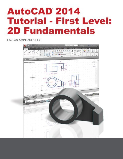
AutoCAD 2014<br />
Tutorial - First Level:<br />
<strong>2D</strong> Fundamentals<br />
®<br />
FAZLAN AMINI ZULKIFLY<br />
SDC<br />
P U B L I C A TION S<br />
Schroff Development Corporation
Visit the following websites to learn more about this book:
AutoCAD ® 2014 Tutorial: <strong>2D</strong> Fundamentals 1-1<br />
Chapter 1<br />
AutoCAD Fundamentals<br />
♦ Create and Save AutoCAD drawing files<br />
♦ Use the AutoCAD visual reference<br />
commands<br />
♦ Draw, using the LINE and CIRCLE<br />
commands<br />
♦ Use the ERASE command<br />
♦ Define Positions using the Basic Entry<br />
methods<br />
♦ Use the AutoCAD Pan Realtime option
1-2 AutoCAD ® 2014 Tutorial: <strong>2D</strong> Fundamentals<br />
AutoCAD Certified User Examination Objectives Coverage<br />
This table shows the pages on which the objectives of the Certified User Examination are covered in<br />
Chapter 1.<br />
Section 1: Controlling the Display in Drawings<br />
Precision ...........................................................................1-6<br />
Zoom Extent.....................................................................1-7<br />
Drawing LIMITS ............................................................1-6<br />
Status Bar .........................................................................1-10<br />
GRID Display ..................................................................1-10, 1-11<br />
PAN Realtime ..................................................................1-20<br />
Certified User Reference Guide<br />
Section 2: Creating Basic Drawings<br />
Format ..............................................................................1-5<br />
Units Setup ......................................................................1-5<br />
LINE Command ...............................................................1-8<br />
Coordinates ......................................................................1-8<br />
Interactive Input Method..................................................1-10<br />
SNAP Option ...................................................................1-12<br />
World Space .....................................................................1-15<br />
User Coordinate System ..................................................1-15<br />
World Coordinate System ................................................1-15<br />
UCS Icon Display ............................................................1-16<br />
TTR, Circle ......................................................................1-23<br />
Relative Coordinate .........................................................1-17<br />
Coordinate Systems .........................................................1-17<br />
Cartesian coordinate system ............................................1-17<br />
Absolute Coordinates .......................................................1-17, 1-18<br />
Positions, Defining ...........................................................1-18<br />
LINE, Close Option .........................................................1-19<br />
CIRCLE Command ..........................................................1-23<br />
TTT, Circle ......................................................................1-23<br />
ARC Command ………………………………………... 1-33<br />
Section 3: Manipulating Objects<br />
ERASE Command ..........................................................1-13<br />
Selection Window ............................................................1-14
AutoCAD Fundamentals 1-3<br />
Introduction<br />
Learning to use a CAD system is similar to learning a new language. It is necessary to<br />
begin with the basic alphabet and learn how to use it correctly and effectively through<br />
practice. This will require learning some new concepts and skills as well as learning a<br />
different vocabulary. Today, the majority of the Mechanical CAD systems are capable of<br />
creating three-dimensional solid models. Nonetheless, all CAD systems create designs<br />
using basic geometric entities and many of the constructions used in technical designs are<br />
based upon two-dimensional planar geometry. The method and number of operations that<br />
are required to accomplish the basic planar constructions are different from one system to<br />
another.<br />
In order to become effective and efficient in using a CAD system, we must learn to create<br />
geometric entities quickly and accurately. In learning to use a CAD system, lines and<br />
circles are the first two, and perhaps the most important two, geometric entities that one<br />
should master the skills of creating and modifying. Straight lines and circles are used in<br />
almost all technical designs. In examining the different types of planar geometric entities,<br />
the importance of lines and circles becomes obvious. Triangles and polygons are planar<br />
figures bounded by straight lines. Ellipses and splines can be constructed by connecting<br />
arcs with different radii. As one gains some experience in creating lines and circles,<br />
similar procedures can be applied to create other geometric entities. In this chapter, the<br />
different ways of creating lines and circles in AutoCAD ® 2014 are examined.<br />
Starting Up AutoCAD ® 2014<br />
1. Select the AutoCAD 2014 option on the Program menu or select the AutoCAD<br />
2014 icon on the Desktop.<br />
Once the program is loaded into memory, the AutoCAD ® 2014 drawing screen<br />
will appear on the screen.
1-4 AutoCAD ® 2014 Tutorial: <strong>2D</strong> Fundamentals<br />
Note that AutoCAD automatically assigns generic names, Drawing X, as new<br />
drawings are created. In our example, AutoCAD opened the graphics window using<br />
the default system units and assigned the drawing name Drawing1.<br />
2. If necessary, click on the down-arrow in the Quick Access bar and select Show<br />
Menu to display the AutoCAD Menu Bar. The Menu Bar provides access to all<br />
AutoCAD commands.<br />
AutoCAD Menu Bar
AutoCAD Fundamentals 1-5<br />
Drawing Units Setup<br />
Every object we construct in a CAD system is measured in units. We should<br />
determine the system of units within the CAD system before creating the first<br />
geometric entities.<br />
1. In the Menu Bar select:<br />
[Format] [Units]<br />
• The AutoCAD Menu Bar contains multiple pull-down<br />
menus, where all of the AutoCAD commands can be<br />
accessed. Note that many of the menu items listed in<br />
the pull-down menus can also be accessed through the<br />
Quick Access toolbar and/or Ribbon panels.<br />
2. Click on the Length<br />
Type option to display<br />
the different types of<br />
length units available.<br />
Confirm the Length<br />
Type is set to<br />
Decimal.<br />
3. On your own, examine the other settings that are<br />
available.<br />
4. In the Drawing Units dialog box, set the Length Type to Decimal. This will set<br />
the measurement to the default English units, inches.
1-6 AutoCAD ® 2014 Tutorial: <strong>2D</strong> Fundamentals<br />
5. Set the Precision to two digits<br />
after the decimal point as shown in<br />
the above figure.<br />
6. Pick OK to exit the Drawing Units<br />
dialog box.<br />
Drawing Area Setup<br />
Next, we will set up the Drawing Limits by entering a command in the<br />
command prompt area. Setting the Drawing Limits controls the extents of the<br />
display of the grid. It also serves as a visual reference that marks the working<br />
area. It can also be used to prevent construction outside the grid limits and as a<br />
plot option that defines an area to be plotted/printed. Note that this setting does<br />
not limit the region for geometry construction.<br />
1. In the Menu Bar select:<br />
[Format] [Drawing Limits]<br />
2. In the command prompt area, the message “Reset Model<br />
Space Limits: Specify lower left corner or [On/Off]<br />
:” is displayed. Press the ENTER key once to<br />
accept the default coordinates .<br />
3. In the command prompt area, the message “Specify upper right corner<br />
:” is displayed. Press the ENTER key again to accept the default<br />
coordinates .
AutoCAD Fundamentals 1-7<br />
4. On your own, move the graphics cursor near the upper-right comer inside the<br />
drawing area and note that the drawing area is unchanged. (The Drawing Limits<br />
command is used to set the drawing area, but the display will not be adjusted until<br />
a display command is used.)<br />
5. Inside the Menu Bar area<br />
select:<br />
[View] [Zoom] [All]<br />
The Zoom All command will<br />
adjust the display so that all<br />
objects in the drawing are<br />
displayed to be as large as<br />
possible. If no objects are<br />
constructed, the Drawing<br />
Limits are used to adjust the<br />
current viewport.<br />
6. Move the graphics cursor near the upper-right comer inside the drawing area and<br />
note that the display area is updated.<br />
7. Hit the function key [F7] once to turn off the display of the Grid lines.<br />
• Note that function key [F7] is a quick key, which can be used to quickly toggle<br />
on/off the grid display. Also, note the command prompt area can be positioned to<br />
dock below the drawing area or float inside the drawing area as shown.
1-8 AutoCAD ® 2014 Tutorial: <strong>2D</strong> Fundamentals<br />
Drawing Lines with the LINE Command<br />
1. Move the graphics cursor to the first icon in<br />
the Draw panel. This icon is the Line icon.<br />
Note that a brief description of the Line<br />
command appears next to the cursor.<br />
2. Select the icon by clicking once with the leftmouse-button,<br />
which will activate the Line<br />
command.<br />
3. In the command prompt area, near the bottom of the AutoCAD drawing screen,<br />
the message “_line Specify first point:” is displayed. AutoCAD expects us to<br />
identify the starting location of a straight line. Move the graphics cursor inside the<br />
graphics window and watch the display of the coordinates of the graphics cursor<br />
at the bottom of the AutoCAD drawing screen. The three numbers represent the<br />
location of the cursor in the X, Y, and Z directions. We can treat the graphics<br />
window as if it was a piece of paper and we are using the graphics cursor as if it<br />
were a pencil with which to draw.<br />
Coordinates of the graphics<br />
cursor<br />
3 2<br />
5<br />
We will create a freehand sketch of a fivepoint<br />
star using the Line command. Do not be<br />
overly concerned with the actual size or<br />
accuracy of your freehand sketch. This<br />
exercise is to give you a feel for the<br />
AutoCAD ® 2014 user interface.<br />
1 4
AutoCAD Fundamentals 1-9<br />
4. We will start at a location about one-third<br />
from the bottom of the graphics window.<br />
Left-click once to position the starting<br />
point of our first line. This will be point 1<br />
of our sketch. Next move the cursor<br />
upward and toward the right side of point<br />
1. Notice the rubber-band line that follows<br />
the graphics cursor in the graphics<br />
window. Left-click again (point 2) and we<br />
have created the first line of our sketch.<br />
5. Move the cursor to the left of point 2 and<br />
create a horizontal line about the same<br />
length as the first line on the screen.<br />
5<br />
3 2<br />
6. Repeat the above steps and complete the<br />
freehand sketch by adding three more<br />
lines (from point 3 to point 4, point 4 to<br />
point 5, and then connect to point 5 back<br />
to point 1).<br />
1 4<br />
7. Notice that the Line command remains activated even after<br />
we connected the last segment of the line to the starting<br />
point (point 1) of our sketch. Inside the graphics window,<br />
click once with the right-mouse-button and a popup menu<br />
appears on the screen.<br />
8. Select Enter with the left-mouse-button to end the Line<br />
command. (This is equivalent to hitting the [ENTER] key on<br />
the keyboard.)<br />
9. Move the cursor near point 2 and point 3, and estimate the<br />
length of the horizontal line by watching the displayed<br />
coordinates for each point.
1-10 AutoCAD ® 2014 Tutorial: <strong>2D</strong> Fundamentals<br />
Visual Reference<br />
The method we just used to create the freehand sketch is known as the interactive<br />
method, where we use the cursor to specify locations on the screen. This method is<br />
perhaps the fastest way to specify locations on the screen. However, it is rather difficult<br />
to try to create a line of a specific length by watching the displayed coordinates. It would<br />
be helpful to know what one inch or one meter looks like on the screen while we are<br />
creating entities. AutoCAD ® 2014 provides us with many tools to aid the construction of<br />
our designs. For example, the GRID and SNAP MODE options can be used to get a<br />
visual reference as to the size of objects and learn to restrict the movement of the cursor<br />
to a set increment on the screen.<br />
The GRID and SNAP MODE options can be turned ON or OFF through the Status Bar.<br />
The Status Bar area is located at the bottom left of the AutoCAD drawing screen, next to<br />
the cursor coordinates.<br />
Option Buttons<br />
The second button in the Status Bar is the SNAP MODE option and the third button is the<br />
GRID DISPLAY option. Note that the buttons in the Status Bar area serve two functions:<br />
(1) the status of the specific option, and (2) as toggle switches that can be used to turn<br />
these special options ON and OFF. When the corresponding button is highlighted, the<br />
specific option is turned ON. Using the buttons is a quick and easy way to make changes<br />
to these drawing aid options. The buttons in the Status Bar can also be switched on and<br />
off in the middle of another command.
AutoCAD Fundamentals 1-11<br />
GRID ON<br />
1. Left-click the GRID button in the Status Bar to turn ON the GRID DISPLAY<br />
option. (Notice in the command prompt area, the message “” is also<br />
displayed.)<br />
2. Move the cursor inside the graphics window, and estimate the distance in between<br />
the grid lines by watching the coordinates displayed at the bottom of the screen.<br />
The GRID option creates a pattern of lines that extends over an area on the screen.<br />
Using the grid is similar to placing a sheet of grid paper under a drawing. The grid<br />
helps you align objects and visualize the distance between them. The grid is not<br />
displayed in the plotted drawing. The default grid spacing, which means the distance<br />
in between two lines on the screen, is 0.5 inches. We can see that the sketched<br />
horizontal line in the sketch is about 4.5 inches long.
1-12 AutoCAD ® 2014 Tutorial: <strong>2D</strong> Fundamentals<br />
SNAP MODE ON<br />
1. Left-click the SNAP MODE button in the Status Bar to turn ON the SNAP option.<br />
2. Move the cursor inside the graphics window, and move the cursor diagonally on<br />
the screen. Observe the movement of the cursor and watch the coordinates<br />
display at the bottom of the screen.<br />
The SNAP option controls an invisible rectangular grid that restricts cursor<br />
movement to specified intervals. When SNAP mode is on, the screen cursor and<br />
all input coordinates are snapped to the nearest point on the grid. The default snap<br />
interval is 0.5 inches, and aligned to the grid points on the screen.<br />
3. Click on the Line icon in the Draw toolbar. In the<br />
command prompt area, the message “_line Specify<br />
first point:” is displayed.<br />
4. On your own, create another sketch of the five-point star with the GRID and<br />
SNAP options switched ON.<br />
5. Use the right-mouse-button and select Enter in the popup<br />
menu to end the Line command if you have not done so.
AutoCAD Fundamentals 1-13<br />
Using the ERASE Command<br />
One of the advantages of using a CAD system is the ability to remove entities without<br />
leaving any marks. We will erase two of the lines using the Erase command.<br />
1. Pick Erase in the Modify toolbar. (The<br />
icon is a picture of an eraser at the end<br />
of a pencil.) The message “Select<br />
objects” is displayed in the command<br />
prompt area and AutoCAD awaits us to<br />
select the objects to erase.<br />
2. Left-click the SNAP MODE button on the Status Bar to turn OFF the SNAP<br />
MODE option so that we can more easily move the cursor on top of objects. We<br />
can toggle the Status Bar options ON or OFF in the middle of another command.<br />
3. Select any two lines on the screen; the selected lines are displayed as dashed lines<br />
as shown in the figure below.<br />
To deselect an object from the selection set, hold down the [SHIFT] key and select<br />
the object again.<br />
4. Right-mouse-click once to accept the selections. The selected two lines are<br />
erased.
1-14 AutoCAD ® 2014 Tutorial: <strong>2D</strong> Fundamentals<br />
Repeat the Last Command<br />
1. Inside the graphics window, click once with the right-mousebutton<br />
to bring up the popup option menu.<br />
2. Pick Repeat Erase, with the left-mouse-button, in the popup<br />
menu to repeat the last command. Notice the other options<br />
available in the popup menu.<br />
AutoCAD ® 2014 offers many options to accomplish the same<br />
task. Throughout this text, we will emphasize the use of the<br />
AutoCAD Heads-up Design TM interface, which means we<br />
focus on the screen, not on the keyboard.<br />
3. Move the cursor to a location that is above and toward the left<br />
side of the entities on the screen. Left-mouse-click once to<br />
start a corner of a rubber-band window.<br />
First corner<br />
Second corner<br />
4. Move the cursor toward the right and below the entities, and then left-mouse-click<br />
to enclose all the entities inside the selection window. Notice all entities that are<br />
inside the window are selected.<br />
5. Inside the graphics window, right-mouse-click once to proceed with erasing<br />
the selected entities.<br />
On your own, create a free-hand sketch of your choice using the Line command.<br />
Experiment with using the different commands we have discussed so far. Reset the<br />
status buttons so that only the GRID DISPLAY option is turned ON as shown.
AutoCAD Fundamentals 1-15<br />
The CAD Database and the User Coordinate System<br />
Designs and drawings created in a CAD system are<br />
usually defined and stored using sets of points in<br />
what is called world space. In most CAD systems,<br />
the world space is defined using a three-dimensional<br />
Cartesian coordinate system. Three mutually<br />
perpendicular axes usually referred to as the X-, Y-,<br />
and Z-axes, define this system. The intersection of<br />
the three coordinate axes forms a point called the<br />
origin. Any point in world space can then be defined<br />
as the distance from the origin in the X-, Y- and Z-<br />
directions. In most CAD systems, the directions of<br />
the arrows shown on the axes identify the positive<br />
sides of the coordinates.<br />
A CAD file, which is the electronic version of the design, contains data that describes the<br />
entities created in the CAD system. Information such as the coordinate values in world<br />
space for all endpoints, center points, etc., along with the descriptions of the types of<br />
entities are all stored in the file. Knowing that AutoCAD stores designs by keeping<br />
coordinate data helps us understand the inputs required to create entities.<br />
3D UCS icon<br />
The icon near the bottom left corner of the default AutoCAD graphics window shows the<br />
positive X-direction and positive Y-direction of the coordinate system that is active. In<br />
AutoCAD, the coordinate system that is used to create entities is called the user<br />
coordinate system (UCS). By default, the user coordinate system is aligned to the<br />
world coordinate system (WCS). The world coordinate system is a coordinate system<br />
used by AutoCAD as the basis for defining all objects and other coordinate systems<br />
defined by the users. We can think of the origin of the world coordinate system as a<br />
fixed point being used as a reference for all measurements. The default orientation of the<br />
Z-axis can be considered as positive values in front of the monitor and negative values<br />
inside the monitor.
1-16 AutoCAD ® 2014 Tutorial: <strong>2D</strong> Fundamentals<br />
Changing to the <strong>2D</strong> UCS Icon Display<br />
In AutoCAD ® 2014, the UCS icon is displayed in various ways to help us<br />
visualize the orientation of the drawing plane.<br />
1. Click on the View pull-down<br />
menu and select<br />
[Display] [UCS Icon] <br />
[Properties]<br />
2. In the UCS icon style section, switch to the <strong>2D</strong> option as shown.<br />
3. Click OK to accept the settings.<br />
Note the W symbol in the UCS<br />
icon indicates that the UCS is<br />
aligned to the world coordinate<br />
system.
AutoCAD Fundamentals 1-17<br />
Cartesian and Polar Coordinate Systems<br />
In a two-dimensional space, a point can be represented using different coordinate<br />
systems. The point can be located, using a Cartesian coordinate system, as X and Y units<br />
away from the origin. The same point can also be located using the polar coordinate<br />
system, as r and θ units away from the origin.<br />
For planar geometry, the polar coordinate system is very useful for certain applications.<br />
In the polar coordinate system, points are defined in terms of a radial distance, r, from the<br />
origin and an angle θ between the direction of r and the positive X axis. The default<br />
system for measuring angles in AutoCAD ® 2014 defines positive angular values as<br />
counter-clockwise from the positive X-axis.<br />
Absolute and Relative Coordinates<br />
• AutoCAD ® 2014 also allows us to use<br />
absolute and relative coordinates to quickly<br />
construct objects. Absolute coordinate<br />
values are measured from the current<br />
coordinate system's origin point. Relative<br />
coordinate values are specified in relation to<br />
previous coordinates.<br />
Note that the coordinate display area can<br />
also be used as a toggle switch; each leftmouse-click<br />
will toggle the coordinate<br />
display on or off.<br />
In AutoCAD ® 2014, the absolute coordinates and the relative coordinates can be used in<br />
conjunction with the Cartesian and polar coordinate systems. By default, AutoCAD<br />
expects us to enter values in absolute Cartesian coordinates, distances measured from the<br />
current coordinate system's origin point. We can switch to using the relative coordinates<br />
by using the @ symbol. The @ symbol is used as the relative coordinates specifier,<br />
which means that we can specify the position of a point in relation to the previous point.
1-18 AutoCAD ® 2014 Tutorial: <strong>2D</strong> Fundamentals<br />
Defining Positions<br />
In AutoCAD, there are five methods for specifying the locations of points when we<br />
create planar geometric entities.<br />
Interactive method: Use the cursor to select on the screen.<br />
Absolute coordinates (Format: X,Y): Type the X and Y coordinates to locate the<br />
point on the current coordinate system relative to the origin.<br />
Relative rectangular coordinates (Format: @X,Y): Type the X and Y<br />
coordinates relative to the last point.<br />
Relative polar coordinates (Format: @Distance
AutoCAD Fundamentals 1-19<br />
The GuidePlate<br />
We will next create a mechanical design using the different coordinate entry methods.<br />
The rule for creating CAD designs and drawings is that they should be created at full<br />
size using real-world units. The CAD database contains all the definitions of the<br />
geometric entities and the design is considered as a virtual, full-sized object. Only<br />
when a printer or plotter transfers the CAD design to paper is the design scaled to fit<br />
on a sheet. The tedious task of determining a scale factor so that the design will fit on<br />
a sheet of paper is taken care of by the CAD system. This allows the designers and<br />
CAD operators to concentrate their attention on the more important issues – the<br />
design.<br />
1. Select the Line command icon in the Draw<br />
toolbar. In the command prompt area, near the<br />
bottom of the AutoCAD graphics window, the<br />
message “_line Specify first point:” is displayed.<br />
AutoCAD expects us to identify the starting<br />
location of a straight line.<br />
2. We will locate the starting point of our design at<br />
the origin of the world coordinate system.<br />
Command: _line Specify first point: 0,0<br />
(Type 0,0 and press the [ENTER] key once.)
1-20 AutoCAD ® 2014 Tutorial: <strong>2D</strong> Fundamentals<br />
3. We will create a horizontal line by entering the absolute coordinates of the second<br />
point.<br />
Specify next point or [Undo]: 5.5,0 [ENTER]<br />
(0,0)<br />
(5.5,0)<br />
• Note that the line we created is aligned to the bottom edge of the drawing<br />
window. Let us adjust the view of the line by using the Pan Realtime command.<br />
4. In the Menu Bar area select: [View] [Pan] [Realtime]<br />
The available Pan commands enable us to move the view to a different position.<br />
The Pan-Realtime function acts as if you are using a video camera.<br />
5. Move the cursor, which appears as a hand inside the graphics window, near the<br />
center of the drawing window, then push down the left-mouse-button and drag<br />
the display toward the right and top side until we can see the sketched line.<br />
(Notice the scroll bars can also be used to adjust viewing of the display.)
AutoCAD Fundamentals 1-21<br />
6. Press the [Esc] key to exit the Pan-Realtime command. Notice that AutoCAD<br />
goes back to the Line command.<br />
7. We will create a vertical line by using the relative rectangular coordinates entry<br />
method, relative to the last point we specified:<br />
Specify next point or [Close/Undo]: @0,2.5 [ENTER]<br />
8. We can mix any of the entry methods in positioning the locations of the<br />
endpoints. Move the cursor to the Status Bar area, and turn ON the SNAP MODE<br />
option.<br />
Note that the Line command is resumed as the settings are adjusted.<br />
9. Left-click once on the coordinates<br />
display area to switch to a different<br />
coordinate display option. Each click<br />
will change the coordinate display.<br />
10. Note the coordinates display area has<br />
changed to show the length of the new<br />
line and its angle. Left-click once on the<br />
coordinates display area to switch back<br />
to using the world coordinate system.<br />
11. Create the next line by picking the<br />
location, world coordinates (8,2.5), on<br />
the screen.
1-22 AutoCAD ® 2014 Tutorial: <strong>2D</strong> Fundamentals<br />
12. We will next use the relative polar coordinates entry method, relative to the last<br />
point we specified:<br />
Specify next point or [Close/Undo]: @3
AutoCAD Fundamentals 1-23<br />
Creating Circles<br />
• The menus and toolbars in AutoCAD ® 2014 are designed to allow the CAD<br />
operator to quickly activate the desired commands.<br />
1. In the Draw toolbar, click on the little<br />
triangle below the circle icon. Note that the<br />
little triangle indicates additional options are<br />
available.<br />
2. In the option list, select: [Center, Diameter]<br />
Notice the different options available under the circle submenu:<br />
• Center, Radius: Draws a circle based on a center point and a radius.<br />
• Center, Diameter: Draws a circle based on a center point and a diameter.<br />
• 2 Points: Draws a circle based on two endpoints of the diameter.<br />
• 3 Points: Draws a circle based on three points on the circumference.<br />
• TTR–Tangent, Tangent, Radius: Draws a circle with a specified radius<br />
tangent to two objects.<br />
• TTT–Tangent, Tangent, Tangent: Draws a circle tangent to three objects.
1-24 AutoCAD ® 2014 Tutorial: <strong>2D</strong> Fundamentals<br />
3. In the command prompt area, the message “Specify center point for circle or<br />
[3P/2P/Ttr (tan tan radius)]:” is displayed. AutoCAD expects us to identify the<br />
location of a point or enter an option. We can use any of the four coordinate entry<br />
methods to identify the desired location. We will enter the world coordinates<br />
(2.5,3) as the center point for the first circle.<br />
Specify center point for circle or [3P/2P/Ttr (tan tan radius)]: 2.5,3 [ENTER]<br />
4. In the command prompt area, the message “Specify diameter of circle:” is<br />
displayed.<br />
Specify diameter of circle: 2.5 [ENTER]<br />
5. Inside the graphics window, right-mouse-click to<br />
bring up the popup option menu.<br />
6. Pick Repeat CIRCLE with the left-mouse-button<br />
in the popup menu to repeat the last command.<br />
7. Using the relative rectangular coordinates entry<br />
method, relative to the center-point coordinates of<br />
the first circle, we specify the location as (2.5,2).<br />
Specify center point for circle or [3P/2P/Ttr (tan tan radius)]: @2.5,2 [ENTER]
AutoCAD Fundamentals 1-25<br />
8. In the command prompt area, the message “Specify Radius of circle: ” is<br />
displayed. The default option for the Circle command in AutoCAD is to specify<br />
the radius and the last radius used is also displayed in brackets.<br />
9. Inside the graphics window, right-mouse-click to bring up<br />
the popup option menu and select Diameter as shown.<br />
10. In the command prompt area, enter 1.5 as the diameter.<br />
Specify Diameter of circle: 1.5 [ENTER]<br />
Saving the CAD Design<br />
1. In the Application Menu, select:<br />
[Application] [Save]<br />
Note the command can also be activated with quickkey<br />
combination of [Ctrl]+[S].
1-26 AutoCAD ® 2014 Tutorial: <strong>2D</strong> Fundamentals<br />
2. In the Save Drawing As dialog box, select the folder in which you want to store<br />
the CAD file and enter GuidePlate in the File name box.<br />
Select the folder<br />
to store the file.<br />
Enter GuidePlate<br />
3. Click Save in the Save Drawing As dialog box to accept the selections and save<br />
the file. Note the default file type is DWG, which is the standard AutoCAD<br />
drawing format.<br />
Close the Current Drawing<br />
Several options are available to close the current drawing:<br />
Select [Close] [Current<br />
Drawing] in the Application<br />
Menu Bar as shown.<br />
Enter Close at the command<br />
prompt.<br />
The third option is to click on the [Close] icon, located at<br />
the upper-right-hand corner of the drawing window.
AutoCAD Fundamentals 1-27<br />
The Spacer Design<br />
We will next create the spacer design using more of AutoCAD’s drawing tools.<br />
Start a New Drawing<br />
1. In the Application Menu, select [New] to start a new<br />
drawing.<br />
2. The Select Template<br />
dialog box appears on<br />
the screen. Accept the<br />
default acad.dwt as the<br />
template to open.<br />
The dwt file type is the<br />
AutoCAD template file<br />
format. An AutoCAD<br />
template file contains predefined<br />
settings to reduce<br />
the amount of tedious<br />
repetitions.
1-28 AutoCAD ® 2014 Tutorial: <strong>2D</strong> Fundamentals<br />
Drawing Units Setup<br />
Every object we construct in a CAD system is measured in units. We should<br />
determine the system of units within the CAD system before creating the first<br />
geometric entities.<br />
1. In the Menu Bar select:<br />
[Format] [Units]<br />
• The AutoCAD Menu Bar contains multiple pull-down<br />
menus, where all of the AutoCAD commands can be<br />
accessed. Note that many of the menu items listed in<br />
the pull-down menus can also be accessed through the<br />
Quick Access toolbar and/or Ribbon panels.<br />
2. Click on the Length Type<br />
option to display the different<br />
types of length units<br />
available. Confirm the<br />
Length Type is set to<br />
Decimal.<br />
3. On your own, examine the other settings that are<br />
available.<br />
4. In the Drawing Units dialog box, set the Length Type to Decimal. This will set the<br />
measurement to the default English units, inches.
AutoCAD Fundamentals 1-29<br />
5. Set the Precision to two<br />
digits after the decimal point<br />
as shown in the above figure.<br />
6. Pick OK to exit the Drawing<br />
Units dialog box.<br />
Drawing Area Setup<br />
Next, we will set up the Drawing Limits by entering a command in the<br />
command prompt area. Setting the Drawing Limits controls the extents of the<br />
display of the grid. It also serves as a visual reference that marks the working<br />
area. It can also be used to prevent construction outside the grid limits and as a<br />
plot option that defines an area to be plotted/printed. Note that this setting does<br />
not limit the region for geometry construction.<br />
1. In the Menu Bar select:<br />
[Format] [Drawing Limits]<br />
2. In the command prompt area, the message “Reset Model<br />
Space Limits: Specify lower left corner or [On/Off]<br />
:” is displayed. Press the ENTER key once to<br />
accept the default coordinates .<br />
3. In the command prompt area, the message “Specify upper right corner<br />
:” is displayed. Press the ENTER key again to accept the default<br />
coordinates .
1-30 AutoCAD ® 2014 Tutorial: <strong>2D</strong> Fundamentals<br />
4. On your own, move the graphics cursor near the upper-right comer inside the<br />
drawing area and note that the drawing area is unchanged. (The Drawing Limits<br />
command is used to set the drawing area, but the display will not be adjusted until<br />
a display command is used.)<br />
5. Inside the Menu Bar area select:<br />
[View] [Zoom] [All]<br />
The Zoom All command will<br />
adjust the display so that all objects<br />
in the drawing are displayed to be as<br />
large as possible. If no objects are<br />
constructed, the Drawing Limits are<br />
used to adjust the current viewport.<br />
6. Move the graphics cursor near the<br />
upper-right comer inside the<br />
drawing area, and note that the<br />
display area is updated.<br />
7. In the Status Bar area, right-mouse-click on<br />
SnapMode and choose [Settings].<br />
8. In the Drafting Settings dialog box, switch on the<br />
Snap and Grid options as shown.<br />
On your own, exit the Drafting Settings dialog box and reset the status buttons so<br />
that only GRID DISPLAY and SNAP MODE are turned ON as shown.
AutoCAD Fundamentals 1-31<br />
Using the Line Command<br />
1. Select the Line command icon in the Draw toolbar.<br />
In the command prompt area, near the bottom of the<br />
AutoCAD graphics window, the message “_line<br />
Specify first point:” is displayed. AutoCAD expects<br />
us to identify the starting location of a straight line.<br />
2. To further illustrate the usage of the different input<br />
methods and tools available in AutoCAD, we will<br />
start the line segments at an arbitrary location.<br />
Start at a location that is somewhere in the lower left<br />
side of the graphics window.<br />
3. We will create a<br />
horizontal line by using<br />
the relative rectangular<br />
coordinates entry<br />
method, relative to the<br />
last point we specified:<br />
@6,0 [ENTER]<br />
4. Next, create a vertical line by using the<br />
relative polar coordinates entry<br />
method, relative to the last point we<br />
specified: @3
1-32 AutoCAD ® 2014 Tutorial: <strong>2D</strong> Fundamentals<br />
6. Use the direct distance<br />
entry technique by<br />
entering 2 [ENTER].<br />
7. On your own, repeat the<br />
above steps and create<br />
the four additional line<br />
segments, using the<br />
dimensions as shown.<br />
8. To end the line command, we can either hit the [Enter] key<br />
on the keyboard or use the Enter option, right-mouse-click<br />
and a popup menu appears on the screen.<br />
9. Select Enter with the left-mouse-button to end the Line<br />
command.
AutoCAD Fundamentals 1-33<br />
Using the ERASE Command<br />
The vertical line on the right was created as a construction line, to aide the<br />
construction of the rest of the lines for the design. We will use the Erase command to<br />
remove it.<br />
1. Pick Erase in the Modify toolbar. The<br />
message “Select objects” is displayed in<br />
the command prompt area and<br />
AutoCAD awaits us to select the objects<br />
to erase.<br />
2. Select the vertical<br />
line as shown.<br />
3. Click once with the<br />
right-mouse-button<br />
to accept the<br />
selection and delete<br />
the line.<br />
Using the Arc Command<br />
1. Click the down-arrow icon of the Arc command in the<br />
Draw toolbar to display the different Arc construction<br />
options.<br />
AutoCAD provides eleven different ways to create arcs.<br />
Note that the different options are used based on the<br />
geometry conditions of the design. The more commonly<br />
used options are the 3-Points option and the Center-Start-<br />
End option.<br />
2. Select the Center-Start-End option as shown. This option<br />
requires the selection of the center point, start point and<br />
end point location, in that order, of the arc.
1-34 AutoCAD ® 2014 Tutorial: <strong>2D</strong> Fundamentals<br />
3. Move the cursor to the<br />
middle of the two horizontal<br />
lines and align the cursor to<br />
the two endpoints as shown.<br />
Click once with the rightmouse-button<br />
to select the<br />
location as the center point of<br />
the new arc.<br />
4. Move the cursor downward<br />
and select the right endpoint<br />
of the bottom horizontal line<br />
as the start point of the arc.<br />
5. Move the cursor to the right<br />
endpoint of the top horizontal<br />
line as shown. Pick this point<br />
as the endpoint of the new<br />
arc.<br />
6. On your own, repeat the<br />
above steps and create the<br />
other arc as shown. Note<br />
that in most CAD packages,<br />
positive angles are defined<br />
as going counterclockwise;<br />
therefore the starting point<br />
of the second arc should be<br />
at the endpoint on top.
AutoCAD Fundamentals 1-35<br />
Using the Circle Command<br />
1. Select the [Circle] [Center, Diameter]<br />
option as shown.<br />
2. Select the same<br />
location for the arc<br />
center as the center<br />
point for the new circle.<br />
3. In the command<br />
prompt area, the<br />
message “Specify<br />
diameter of circle:” is<br />
displayed. Specify<br />
diameter of circle:<br />
1.25 [ENTER]<br />
4. On your own, create the other circle and complete the drawing as shown.
1-36 AutoCAD ® 2014 Tutorial: <strong>2D</strong> Fundamentals<br />
Saving the CAD Design<br />
1. In the Quick Access Toolbar, select: [Save]<br />
Note the command can also be activated with quick-key combination of<br />
[Ctrl]+[S].<br />
2. In the Save Drawing As dialog box, select the folder in which you want to store<br />
the CAD file and enter Spacer in the File name box.<br />
3. Click Save in the Save Drawing As dialog box to accept the selections and save<br />
the file. Note the default file type is DWG, which is the standard AutoCAD<br />
drawing format.<br />
Exit AutoCAD 2014<br />
To exit AutoCAD ® 2014, select Exit<br />
AutoCAD in the Menu Bar or type QUIT at<br />
the command prompt. Note the command can<br />
also be activated with quick-key combination<br />
of [Ctrl]+[Q].
AutoCAD Fundamentals 1-37<br />
Review Questions: (Time: 20 minutes)<br />
1. What are the advantages and disadvantages of using CAD systems to create<br />
engineering drawings?<br />
2. What is the default AutoCAD filename extension?<br />
3. How do the GRID and SNAP options assist us in sketching?<br />
4. List and describe the different coordinate entry methods available in AutoCAD?<br />
5. When using the Line command, which option allows us to quickly create a linesegment<br />
connecting back to the starting point?<br />
6. List and describe the two types of coordinate systems commonly used for planar<br />
geometry.<br />
7. Which key do you use to quickly cancel a command?<br />
8. When you use the Pan command, do the coordinates of objects get changed?<br />
9. Find information on how to draw ellipses in AutoCAD through the Autodesk<br />
Exchange, and create the following arc. If it is desired to position the center of the<br />
ellipse to a specific location, which ellipse command is more suitable?<br />
10. Find information on how to draw arcs in AutoCAD through the Autodesk Exchange<br />
and create the following arc. List and describe two methods to create arcs in<br />
AutoCAD.
1-38 AutoCAD ® 2014 Tutorial: <strong>2D</strong> Fundamentals<br />
Exercises:<br />
(All dimensions are in inches.) (Time: 60 minutes)<br />
1. Angle Spacer<br />
2. Base Plate
AutoCAD Fundamentals 1-39<br />
3. T-Clip<br />
4. Channel Plate