Create successful ePaper yourself
Turn your PDF publications into a flip-book with our unique Google optimized e-Paper software.
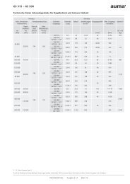
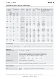
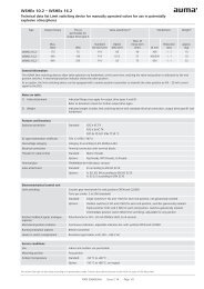
GS 315 – GS 500<br />
Technical data Part-turn gearboxes for open-close duty<br />
Max. valve<br />
torque<br />
to<br />
[Nm]<br />
90,000<br />
63,000<br />
180,000<br />
125,000<br />
125,000<br />
180,000<br />
64,000<br />
180,000<br />
360,000<br />
250,000<br />
360,000<br />
250,000<br />
360,000<br />
Valve<br />
Valve attachment<br />
Flange<br />
according<br />
to<br />
EN ISO<br />
5211<br />
F40 200<br />
F48 250<br />
F60 315<br />
Gearbox/primary<br />
reduction <strong>gearing</strong><br />
Reduction<br />
ratio<br />
Factor 1)<br />
Gearbox<br />
Turns<br />
for 90°<br />
Input shaft 2)<br />
Max. input<br />
torques<br />
Max.<br />
shaft <strong>diameter</strong><br />
[mm] [mm] [Nm]<br />
Weight 3)<br />
GS + GZ<br />
[kg]<br />
GS 315 53:1 23.9 13.25 60 3,766 659<br />
GS 315/<br />
GZ 30.1 - 4:1 4) 212:1 81 53 40 1,111<br />
GS 315/<br />
GZ 30.1 - 8:1<br />
424:1 162 106 30/40 556<br />
GS 315/<br />
GZ 30.1 - 16:1<br />
848:1 325 212 30/40 277 775<br />
GS 315/<br />
GZ 30.1 - 32:1<br />
1,696:1 650 424 20 138<br />
GS 315/<br />
GZ 30.1 - 40:1 4) 2,120.1 813 530 20 78<br />
GS 400 54:1 24.3 13.5 80 7,407 980<br />
GS 400/<br />
GZ 35.1 - 4:1 4) 216:1 82 54 50 1,528<br />
GS 400/<br />
GZ 35.1 - 6:1 4) 324:1 123 81 40 1,016<br />
GS 400/<br />
GZ 35.1 - 8:1<br />
432:1 165 108 40 1,091<br />
GS 400/<br />
GZ 35.1 - 8:1 4) 432:1 165 108 30 388<br />
1,100<br />
GS 400/<br />
864:1 331 216<br />
544<br />
GZ 35.1 - 16:1<br />
30<br />
GS 400/<br />
1,728:1 661 432 272<br />
GZ 35.1 - 32:1<br />
GS 500 52:1 23.4 13 100 15,385 1,800<br />
GS 500/<br />
GZ 40.1 - 8:1 4) 416:1 145 104 40 1,724<br />
GS 500/<br />
GZ 40.1 - 16:1<br />
832:1 318 208 40 1,132<br />
GS 500/<br />
GZ 40.1 - 32:1<br />
1,664:1 636 416<br />
566<br />
2,000<br />
GS 500/<br />
GZ 40.1 - 45:1 4) 2,340:1 809 585 30<br />
309<br />
GS 500/<br />
GZ - 64:1<br />
3,328:1 1 147 832 314 2,030<br />
1) – 4) Refer to notes on page 2.<br />
We reserve the right to alter data according to improvements made. Previous documents become invalid with the issue of this document.<br />
Y004.457/003/en Issue 2.14 Page 1/5
GS 315 – GS 500<br />
Technical data Part-turn gearboxes for open-close duty<br />
Gearbox/primary<br />
reduction <strong>gearing</strong><br />
Reduct.<br />
ratio<br />
Possible combinations with multi-turn actuators Multi-turn actuator Input mounting flange<br />
for mounting multi-turn<br />
actuator<br />
Operating time for 50 Hz 6) in seconds for 90°<br />
at actuator output speed in rpm<br />
Actuator for max.<br />
input torque<br />
Max.<br />
weight 5)<br />
16 22 32 45 63 90 125 180 EN 5210 DIN 3210<br />
GS+GZ+SA<br />
[kg]<br />
GS 315 53:1 50 36 25 – 7 – 7) – 7) – – SA 30.1 F30 – 919<br />
GS 315/<br />
GZ 30.1 - 4:1 4) 212:1 199 145 99 71 50 35 25 – 7) SA 16.2 F16 G3 857<br />
GS 315/<br />
GZ 30.1 - 8:1<br />
424:1 398 289 199 141 101 71 51 35 SA 14.6 F14 G1/2 828<br />
GS 315/<br />
GZ 30.1 - 16:1<br />
848:1 795 578 398 283 202 141 102 71 SA 14.2 F14 G1/2 823<br />
GS 315/<br />
GZ 30.1 - 32:1<br />
1,696:1 – – 795 565 404 283 204 141 SA 10.2 F10 G0 800<br />
GS 315/<br />
GZ 30.1 - 40:1 4) 2,120.1 – – – 707 505 353 254 177 SA 10.2 F10 G0 800<br />
GS 400 54:1 51 37 – 7) – 7) – 7) – 7) – – SA 35.1 F35 – 1,405<br />
GS 400/<br />
GZ 35.1 - 4:1 4) 216:1 203 147 101 72 51 36 – – SA 25.1 F25 G4 1,260<br />
GS 400/<br />
GZ 35.1 - 6:1 4) 324:1 304 221 152 108 77 54 39 27 SA 16.2 F16 G3 1,183<br />
GS 400/<br />
GZ 35.1 - 8:1<br />
432:1 405 295 203 144 103 72 52 36 SA 16.2 F16 G3 1,183<br />
GS 400/<br />
GZ 35.1 - 8:1 4) 432:1 405 295 203 144 103 72 52 36 SA 14.6 F14 G1/2 1,153<br />
GS 400/<br />
GZ 35.1 - 16:1<br />
864:1 810 589 405 288 206 144 104 72 SA 14.6 F14 G1/2 1,153<br />
GS 400/<br />
GZ 35.1 - 32:1<br />
1,728:1 – – 810 576 411 288 207 144 SA 14.2 F14 G1/2 1,148<br />
GS 500 52:1 49 35 – 7) – 7) – 7) – 7) – – SA 40.1 F40 – 2,380<br />
GS 500/<br />
GZ 40.1 - 8:1 4) 416:1 390 284 195 139 99 69 50 35 SA 25.1 F25 – 2,160<br />
GS 500/<br />
GZ 40.1 - 16:1<br />
832:1 780 567 390 277 198 139 100 69 SA 16.2 F16 G3 2,083<br />
GS 500/<br />
GZ 40.1 - 32:1<br />
1,664:1 – – 780 555 396 277 200 139 SA 14.6 F14 G1/2 2,053<br />
GS 500/<br />
GZ 40.1 - 45:1 4) 2,340:1 – – – 780 557 390 281 195 SA 14.6 F14 G1/2 2,053<br />
GS 500/<br />
GZ - 64:1<br />
3,328:1 – – – – 792 555 399 277 SA 14.2 F14 G1/2 2,048<br />
General information<br />
Worm gearboxes for motor or manual operation of valves (e.g. butterfly valves, ball and plug valves). Specific sizing is required for special applications<br />
e.g. dampers or gas diverters. Special applications on request<br />
Notes to table on pages 1 + 2<br />
1) Factor Conversion factor from output torque to input torque to determine the actuator size<br />
For new gearboxes, input torques increased by 15 % are required due to lower efficiency.<br />
2) Input shaft Depending on the required input torque<br />
3) Weight Specified weight includes coupling (without bore) and grease filling in the gear housing<br />
4) Special reduction ratio On request<br />
5) Max. weight Specified weight contains coupling (without bore) and grease filling in the gear housing, multi-turn actuator<br />
with 3-phase AC motor, standard electrical connection, output drive type B3 and handwheel.<br />
6) Operating time for 50 Hz Standard values at 50 Hz; at 60 Hz, the indicated operating time is reduced by 17 %.<br />
7) Refer to Technical Data GS 315 – GS 500 for modulating duty and shorter operating times; heed maximum<br />
valve torque<br />
We reserve the right to alter data according to improvements made. Previous documents become invalid with the issue of this document.<br />
Y004.457/003/en Issue 2.14 Page 2/5
GS 315 – GS 500<br />
Technical data Part-turn gearboxes for open-close duty<br />
Features and functions<br />
Worm wheel material<br />
Spheroidal cast iron<br />
Version Standard: Clockwise rotation RR, counterclockwise rotation LL<br />
Option: RL or LR<br />
Housing material Standard: Cast iron (GJL-250)<br />
Option: Spheroidal cast iron (GJS-400-15)<br />
Self-locking<br />
The gearboxes are self-locking when at standstill under normal service conditions; strong vibration may<br />
cancel the self-locking effect. While in motion, safe braking is not guaranteed. If this is required, a separate<br />
brake must be used.<br />
End stops<br />
Positive for both end positions by travelling nut, sensitive adjustment<br />
Strength of end stop<br />
Guaranteed strength of end stop (in Nm) for input side operation according to AWWA<br />
Type GS 315 GS 400 GS 500<br />
Primary<br />
reduction<br />
GZ 30.1 GZ 35.1 GZ 40.1 GZ 40.1 GZ 16.1<br />
<strong>gearing</strong><br />
Reduction<br />
ratio<br />
8:1 16:1 32:1 8:1 16:1 32:1 16:1 32:1 16:1 4:1<br />
[Nm] 450 250 450 450 450<br />
Strength of end stop for special reduction<br />
ratios<br />
Guaranteed strength of end stop (in Nm) for input side operation<br />
Type GS 315 GS 400 GS 500<br />
Primary<br />
reduction<br />
GZ 30.1 GZ 35.1 GZ 40.1<br />
<strong>gearing</strong><br />
Reduction<br />
ratio<br />
4:1 16:1 40:1 4:1 6:1 8:1 8:1 45:1<br />
[Nm] 450 250 450 450 500<br />
Swing angle GS 315 – GS 500 Standard: Adjustable 0° – 135°; set in the factory to 92° unless ordered otherwise.<br />
Options: Swing angle > 100°, multi-turn without end stops, refer to Technical data GS 315 – GS 500<br />
for modulating duty and shorter operating times<br />
Mechanical position indicator Standard: Pointer cover for continuous position indication<br />
Options: Sealed pointer cover for horizontal outdoor installation<br />
<br />
Protection cover instead of pointer cover for buried service<br />
For gas applications with sealed pointer cover, an air vent in the pointer cover or venting<br />
keyways in the valve mounting flange must be provided.<br />
Input shaft Cylindrical with parallel key according to DIN 6885-1 (refer to table on page 1)<br />
Operation<br />
Motor operation<br />
Type of duty<br />
With electric multi-turn actuator, directly or through GZ primary reduction <strong>gearing</strong><br />
Input mounting flanges for multi-turn actuator (refer to table page 2)<br />
Short-time duty S2 - 15 min (open-close duty)<br />
We reserve the right to alter data according to improvements made. Previous documents become invalid with the issue of this document.<br />
Y004.457/003/en Issue 2.14 Page 3/5
GS 315 – GS 500<br />
Technical data Part-turn gearboxes for open-close duty<br />
Manual operation<br />
Available handwheel <strong>diameter</strong>s according to EN 12570, selection according to output torque:<br />
Type GS 315 GS 400<br />
Primary<br />
reduction – GZ 30.1 – GZ 35.1<br />
<strong>gearing</strong><br />
Reduction<br />
ratio<br />
53:1 212:1 424:1 848:1 1,696:1 2,120.1 54:1 216:1 324:1 432:1 432:1 864:1 1,728:1<br />
Handwheel Ø<br />
[mm]<br />
– – 800 500/800 400 400 – – – – 800 800 500/630<br />
Type GS 500<br />
Primary<br />
reduction – GZ 40.1 GZ - 64:1<br />
<strong>gearing</strong><br />
Reduction<br />
ratio<br />
52:1 416:1 832:1 1,664:1 2,340:1 3,328:1<br />
Handwheel Ø<br />
[mm]<br />
– – – 800 800 500/630<br />
Standard:<br />
Options:<br />
<br />
<br />
<br />
<br />
<br />
Handwheel made of aluminium<br />
Handwheel with ball handle<br />
Handwheel made of GJL-200<br />
Handwheel lockable<br />
WSH limit switching device for signalling position and end positions<br />
Primary reduction <strong>gearing</strong><br />
Primary reduction <strong>gearing</strong><br />
<br />
<br />
Type GZ as planetary <strong>gearing</strong> with various reduction ratios for reducing the input torques (refer to table<br />
page 1).<br />
Combination with GK bevel gearbox directly on GS or on GS with GZ possible (90° deflection of input<br />
shaft)<br />
Valve attachment<br />
Valve attachment<br />
Splined coupling for connection to the<br />
valve shaft<br />
Dimensions according to EN ISO 5211 The maximum torques according to EN ISO 5211 mounting flanges<br />
are to be met.<br />
Standard: With spigot<br />
Standard:<br />
Options:<br />
<br />
With pilot bore<br />
Worm gearbox can be mounted at 4 x 90° increments on coupling<br />
Finish machining with bore and keyway, square bore or two-flat with grub screw for secure<br />
fixing to valve shaft.<br />
Service conditions<br />
Mounting position<br />
Any position<br />
Ambient temperature Standard: –40 °C to +80 °C<br />
Options: –60 °C to +60 °C<br />
0 °C to +120 °C<br />
Enclosure protection according to Standard: IP67<br />
EN 60529<br />
Options: IP68<br />
IP68-10, dust and water tight up to max. 10 m head of water<br />
IP68-20, dust and water tight up to max. 20 m head of water<br />
Corrosion protection Standard: KN Suitable for installation in industrial units, in water or power plants with a low pollutant<br />
concentration<br />
Options: KS Suitable for use in areas with high salinity, almost permanent condensation, and high<br />
pollution.<br />
Paint Standard: Primer coated<br />
Option: Two-component iron-mica combination<br />
KX<br />
Suitable for use in areas with extremely high salinity, permanent condensation, and<br />
high pollution.<br />
We reserve the right to alter data according to improvements made. Previous documents become invalid with the issue of this document.<br />
Y004.457/003/en Issue 2.14 Page 4/5
GS 315 – GS 500<br />
Technical data Part-turn gearboxes for open-close duty<br />
Colour Standard: AUMA silver-grey (similar to RAL 7037)<br />
Lifetime<br />
Option: Available colours on request<br />
Lifetime for 90° swing movement<br />
Gearbox size GS 315 GS 400 GS 500<br />
Number of cycles<br />
for max. torque<br />
2,500 1,200 1,200<br />
AUMA worm gearboxes meet or even exceed the lifetime requirements of EN 15714-2. Detailed information<br />
can be provided on request.<br />
Limit sensing for signalling position and end positions<br />
Valve position indicators<br />
WSG valve position indicator (hall sensors) for position and end position signalling to ensure precise and<br />
low-backlash feedback for swing angles ranging between 82° and 98°.<br />
<br />
WGD valve position indicator (counter gear mechanism) for position and end position signalling for<br />
swing angles > 180°<br />
Special features for use in potentially explosive atmospheres<br />
Explosion protection in accordance II2G c IIC T4<br />
with ATEX 94/9/EC<br />
Type of duty Standard: Short-time duty S2 - 15 min<br />
Ambient temperature Standard: –40 °C to +60 °C (II2G c IIC T4; II2D c T130 °C)<br />
Options: –50 °C to +60 °C<br />
–60 °C to +60 °C<br />
Further information<br />
EU Directives<br />
Reference documents<br />
ATEX Directive: (94/9/EC)<br />
Machinery Directive: (2006/42/EC)<br />
Product description Electric actuators for industrial valve automation<br />
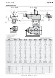
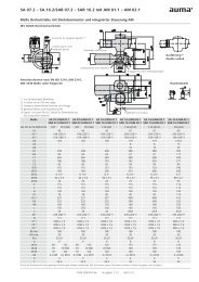
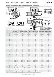
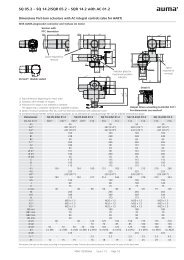
Dimensions GS 315 - GS 500<br />
Technical data SA 07.2 – SA 16.2 with 3-phase AC motors<br />
Technical data SAR 07.2 – SAR 16.2 with 3-phase AC motors<br />
Technical data SA 25.1 – SA 48.1 with 3-phase AC motors<br />
Technical data SAR 25.1 – SAR 30.1 with 3-phase AC motors<br />
Technical data WSG 90.1<br />
Technical data WGD 90.1<br />
Technical data WSH 10.2 – WSH 16.2<br />
We reserve the right to alter data according to improvements made. Previous documents become invalid with the issue of this document.<br />
Y004.457/003/en Issue 2.14 Page 5/5