BETTIS TorqPlus - Model Number Nomenclature - Emerson ...
BETTIS TorqPlus - Model Number Nomenclature - Emerson ...
BETTIS TorqPlus - Model Number Nomenclature - Emerson ...

Create successful ePaper yourself
Turn your PDF publications into a flip-book with our unique Google optimized e-Paper software.
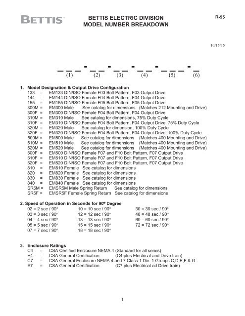
<strong>BETTIS</strong> ELECTRIC DIVISION<br />
MODEL NUMBER BREAKDOWN<br />
R-95<br />
10/15/15<br />
_ _ _ - _ _ - _ _ - _ _ - _ _ _ - _<br />
(1) (2) (3) (4) (5) (6)<br />
1. <strong>Model</strong> Designation & Output Drive Configuration<br />
133 = EM133 DIN/ISO Female F03 Bolt Pattern, F03 Output Drive<br />
144 = EM144 DIN/ISO Female F04 Bolt Pattern, F04 Output Drive<br />
155 = EM155 DIN/ISO Female F05 Bolt Pattern, F05 Output Drive<br />
300M = EM300 Male See catalog for dimensions (Matches 212 Mounting and Drive)<br />
300F = EM300 DIN/ISO Female F04 Bolt Pattern, F04 Output Drive<br />
310M = EM310 Male See catalog for dimensions, 75% Duty Cycle<br />
310F = EM310 DIN/ISO Female F04 Bolt Pattern, F04 Output Drive, 75% Duty Cycle<br />
320M = EM320 Male See catalog for dimension, 100% Duty Cycle<br />
320F = EM320 DIN/ISO Female F04 Bolt Pattern, F04 Output Drive, 100% Duty Cycle<br />
500M = EM500 Male See catalog for dimensions (Matches 400 Mounting and Drive)<br />
510M = EM510 Male See catalog for dimensions (Matches 400 Mounting and Drive)<br />
520M = EM520 Male See catalog for dimensions (Matches 400 Mounting and Drive)<br />
500F = EM500 DIN/ISO Female F07 and F10 Bolt Pattern, F07 Output Drive<br />
510F = EM510 DIN/ISO Female F07 and F10 Bolt Pattern, F07 Output Drive<br />
520F =<br />
810 = EM810 Female See catalog for dimensions<br />
820 = EM820 Female See catalog for dimensions<br />
830 = EM830 Female See catalog for dimensions<br />
840 = EM840 Female See catalog for dimensions<br />
EM520 DIN/ISO Female F07 and F10 Bolt Pattern, F07 Output Drive<br />
SR5M = EMSR5M Male Spring Return See catalog for dimensions<br />
SR5F = EMSR5F Female Spring Return See catalog for dimensions<br />
2. Speed of Operation in Seconds for 90 Degree<br />
02 = 2 sec / 90 10 = 10 sec / 90 30 = 30 sec / 90<br />
03 = 3 sec / 90 12 = 12 sec / 90 48 = 48 sec / 90<br />
04 = 4 sec / 90 13 = 13 sec / 90 60 = 60 sec / 90<br />
05 = 5 sec / 90 15 = 15 sec / 90 72 = 72 sec / 90<br />
07 = 7 sec / 90 18 = 18 sec / 90<br />
3. Enclosure Ratings<br />
C4 = CSA Certified Enclosure NEMA 4 (Standard for all series)<br />
E4 = CSA General Certification (C4 plus Electrical and Drive train)<br />
C7 = CSA General Enclosure NEMA 4 and 7 Class 1 Div. 1 Groups C,D,E,F & G<br />
E7 = CSA General Certification (C7 plus Electrical ad Drive train)<br />
1
<strong>BETTIS</strong> ELECTRIC DIVISION<br />
MODEL NUMBER BREAKDOWN<br />
R-95<br />
10/15/15<br />
4. Motor Voltages<br />
01 = 24 VAC / 1Ph / 60Hz 12 = 48 VDC **<br />
02 = 115 VAC / 1Ph / 50 or 60Hz 13 = 90 VDC **<br />
03 = 220 VAC / 1Ph / 50 or 60Hz 14 = 125 VDC **<br />
10 = 12 VDC 15 = 37 VDC **<br />
11 = 24 VDC 16 = 74 VDC **<br />
** PLEASE NOTE: These motors are special order and will require a 14 to 16 week lead time.<br />
5. Trim/Options Designation -- Please note: New <strong>Number</strong>s may be added without notice.<br />
001 = Standard includes: EM100 – Brake<br />
EM300 – Heat Resistor & Thermostat, Brake for AC Voltage 4 & 10 sec. Units<br />
EM500 – Heat Resistor & Thermostat (Includes 510 & 520)<br />
EM800 – Heat Resistor & Thermostat, Handwheel, 2 Auxiliary Switches,<br />
and Brake for all units 6,000 lb-in and above<br />
EMSR5- Heat Resistor, Brake<br />
002 = 1 Auxiliary Switch<br />
003 = 2 Auxiliary Switches<br />
004 = Brake<br />
005 = 1 Auxiliary Switch / Brake<br />
006 = 2 Auxiliary Switches / Brake<br />
007 = 1 K Ohm Potentiometer<br />
008 = 1 Auxiliary Switch / 1 K Ohm Potentiometer<br />
009 = 2 Auxiliary Switches / Brake / 1 K Ohm Potentiometer<br />
010 = Brake / 1 K Ohm Pot<br />
015 = 2 Auxiliary Switches / Heater & Thermostat<br />
025 = Handwheel<br />
026 = 4 Auxiliary Switches / Brake / 1 K Ohm Pot<br />
027 = Heater & Thermostat (Em100 Series Only)<br />
028 = Brake / Handwheel<br />
029 = 2 Auxiliary Switches / Handwheel<br />
030 = 2 Auxiliary Switches / Handwheel / Brake<br />
031 = 2 Auxiliary Switches / Handwheel / Brake / 1 K Ohm Potentiometer<br />
034 = 2 Auxiliary Switches/1 K Ohm Potentiometer<br />
035 = Brake / 1 K Ohm Potentiometer / Handwheel<br />
036 = 4 Heaters<br />
040 = 2 Auxiliary Switches / Handwheel<br />
041 = 2 Auxiliary Switches / No Heater or Thermostat<br />
042 = No Heater<br />
049 = 4 Auxiliary Switches<br />
050 = 4 Auxiliary Switches / Brake<br />
051 = 4 Auxiliary Switches / Brake / Handwheel<br />
052 = 2 Auxiliary Switches / Brake / Handwheel / 180° Rotation<br />
093 = Brake / Beacon Indicator (<strong>Model</strong> 800)<br />
094 = Brake / Heater Only<br />
096 = Brake / Extra Heater<br />
2
<strong>BETTIS</strong> ELECTRIC DIVISION<br />
MODEL NUMBER BREAKDOWN<br />
R-95<br />
10/15/15<br />
100 = Modulating (Standard Includes: 4-20ma Positioner, Where 4ma=CW & Fail=CW, Brake,<br />
Potentiometer, Transmitter, Heater and Thermostat)<br />
102 = Modulating / 2 Auxiliary Switches<br />
112 = Modulating / Handwheel<br />
116 = Modulating / 2 Auxiliary Switches / Handwheel<br />
118 = Modulating / Dual 1 K Ohm Potentiometer<br />
120 = Positioning / Modulating / External Wiring<br />
121 = Positioning / Modulating / External Wiring / 2 Auxiliary Switches<br />
122 = Modulating (Includes: 4-20ma Positioner, Where 4ma=CW & Fail=CW, Brake, Potentiometer,<br />
Transmitter, Heater and Thermostat) / 270 Degree Rotation<br />
123 = Modulating / Handwheel / No Brake<br />
124 = 0-10 VDC Positioning/Modulating; 0 v = CW & Fail = CW<br />
128 = Modulating / 2 Auxiliary Switches / 3 Heaters<br />
129 = Modulating / High Resolution<br />
130 = Modulating / No Brake<br />
131 = Modulating / 4 Auxiliary Switches / Handwheel<br />
132 = Modulating / Handwheel / 180 Degree Rotation<br />
133 = Modulating / Dessicant Pack<br />
134 = Modulating (Includes: 4-20ma Positioner, Factory Setting for 4ma=CCW & Fail=CW, Brake,<br />
Potentiometer, and Transmitter) / No Heater<br />
135 = Modulating / 4 Auxiliary Switches<br />
136 = Modulating / 2 Aux Switches / 180 Degree Rotation<br />
137 = Modulating (Includes: 4-20ma Positioner, Factory Setting for 4ma=CCW & Fail=CW, Brake,<br />
Potentiometer, and Transmitter)<br />
138 = Modulating / DHC400 with Transmitter/ High Resolution<br />
139 = Modulating / 180 Degree Rotation / No Heater No Thermostat<br />
140 = Modulating / 180 Degree Rotation<br />
185 = 1 K Ohm Potentiometer / Transmitter / 2 Auxiliary Switches / Handwheel<br />
186 = 1 K Ohm Potentiometer / Transmitter / 4 Auxiliary Switches<br />
187 = Modulating, Extra Heater<br />
188 = Modulating, Extra Heater, Handwheel<br />
189 = 5 K Ohm Pot<br />
190 = Transmitter, Brake, Handwheel<br />
191 = 1 K Ohm Potentiometer / Transmitter / Brake / 2 Auxiliary Switches / Handwheel<br />
192 = Transmitter / 2 Auxiliary Switches<br />
193 = External 4-20ma Modulating / 2 Auxiliary Switches<br />
194 = External 4-20ma Modulating<br />
197 = 1 K Ohm Potentiometer / Transmitter<br />
198 = 1 K Ohm Potentiometer / Transmitter / Brake<br />
199 = 1 K Ohm Potentiometer / Transmitter / Brake / 2 Auxiliary Switches<br />
3
<strong>BETTIS</strong> ELECTRIC DIVISION<br />
MODEL NUMBER BREAKDOWN<br />
R-95<br />
10/15/15<br />
208 = Torque Limiting / 2 Aux. Switches / Handwheel / Local Remote Station / 24 VDC<br />
209 = Relay Current Trip Module / 2 Auxiliary Switches<br />
210 = Speed Control<br />
211 = Speed Control / Brake / Handwheel<br />
212 = Auto Sequence Timer<br />
213 = Speed Control / Brake<br />
214 = 1 K Ohm Potentiometer / Transmitter / Handwheel<br />
215 = Transmitter / 2 Auxiliary Switches / No Heater No Thermostat / No Circuit Breaker<br />
216 = 1 K Ohm Potentiometer / Transmitter / Handwheel / 2 Auxiliary Switches<br />
305 = Spring Return – CW<br />
306 = Spring Return – CW / Modulating In Separate Box Mounted to Actuator<br />
307 = Spring Return – CW / 2 Auxiliary Switches<br />
308 = Spring Return – CCW / Modulating in Separate Box Mounted to Actuator<br />
309 = Spring Return – CW / 2 Wire Control Relay 120 VAC Coil<br />
310 = Spring Return – CW / Modulating in Separate Box Mounted to Actuator / 2 Auxiliary Switch<br />
311 = Spring Return – CW / Modulating in Separate Box for Wall Mounting<br />
312 = Spring Return – CW / Close Coupled Local-Remote Station<br />
313 = Spring Return – CW / Modulating, No Separate Box<br />
314 = Spring Return – CW / Modulating, No Separate Box / 2 Auxiliary Switches<br />
315 = Spring Return – CW / Modulating in Separate Box for Wall Mounting / 2 Auxiliary Switches<br />
316 = Spring Return – CW / 2 Wire Control Relay 120 VAC Coil / 2 Auxiliary Switches<br />
355 = Spring Return – CCW<br />
356 = Spring Return – CCW / Modulating, No Separate Box<br />
357 = Spring Return – CCW / 2 Auxiliary Switches<br />
358 = Spring Return – CCW / Modulating, No Separate Box / 2 Auxiliary Switches<br />
359 = Spring Return – CW / Surge Protector<br />
360 = Spring Return – CW / 2 Auxiliary Switches / 25 Watt Heater<br />
361 = Spring Return – CW / Silicone Free Grease in Spring Pack<br />
362 = Spring Return – CW / 4 Auxiliary Switches<br />
363 = Spring Return – CCW / Transmitter<br />
364 = Spring Return – CW / Local Remote Station / Modulating<br />
365 = Spring Return – CW / Special Motor for Increased Operating Speed / 2 Auxiliary Switches<br />
366 = Spring Return – CW / Special Motor for Increased Operating Speed / 2 Auxiliary Switches,<br />
1 K Ohm Pot / Transmitter<br />
367 = Spring Return – CW / Transmitter<br />
368 = Spring Return – CCW / 2 Wire Control Relay 120 VAC Coil / 2 Auxiliary Switches<br />
369 = Spring Return – CCW / 2 Auxiliary Switches / Extra 25 Watt Heater / High Cycle Brake<br />
370 = Spring Return – CCW / 2 Wire Control Relay 24 VDC Coil / High Cycle Brake / 2 Heaters /<br />
2 Auxiliary Switches<br />
371 = Spring Return – CCW / 2 Heaters<br />
372 = Spring Return – CW / Modulating, No Separate Box / 2 Auxiliary Switches / 2 Heaters<br />
373 = Spring Return – CCW / Modulating, No Separate Box / 2 Auxiliary Switches / 2 Heaters<br />
374 = Spring Return – CW / 2 Wire Control Relay 24 VDC Coil<br />
4
<strong>BETTIS</strong> ELECTRIC DIVISION<br />
MODEL NUMBER BREAKDOWN<br />
R-95<br />
375 = Spring Return – CCW / 2 Wire Control Relay 24 VDC Coil / 2 Auxiliary Switches<br />
376 = Spring Return – CCW / 2 Wire Control Relay 24 VDC Coil<br />
377 = Spring Return – CW / 2 Auxiliary Switches / Extra 25 Watt Heater / High Cycle Brake<br />
378 = Spring Return – CW / 2 Auxiliary Switches / 1 K Ohm Pot / Transmitter/ High cycle Brake<br />
379 = Spring Return – CW / 2 Wire Control Relay 24 VDC Coil / 2 Auxiliary switches<br />
380 = Spring Return – CW / 2 Auxiliary Switches / 25 Watt Heater / Special Wiring For Use With<br />
Control Station<br />
381 = Spring Return – CW / 25 Watt Heater<br />
382 = Spring Return – CWW / Modulating, 4mA = CCW / 20mA = CW<br />
10/15/15<br />
400 = Multi-Turn 5 Turn Box<br />
401 = Multi-Turn 30 Turn Box<br />
402 = Multi-Turn 30 Turn Box / Handwheel<br />
404 = Multi-Turn 30 Turn Box / Brake<br />
407 = Multi-Turn 30 Turn Box / Modulating<br />
411 = Multi-Turn 30 Turn Box / Modulating / Handwheel<br />
412 = Multi-Turn 5 Turn Box / Modulating / Handwheel<br />
414 = Multi-Turn 5 Turn Box / 2 Auxiliary Switches<br />
415 = Multi-Turn 20 Turn Box / Modulating / Handwheel<br />
419 = Multi-Turn 20 Turn Box / Modulating<br />
420 = Multi-Turn 20 Turn Box<br />
423 = Multi- Turn 5 Turn Box / Positioning / Modulating<br />
424 = Multi-Turn 20 Turn Box / Brake / 2 Auxiliary Switches<br />
425 = Multi-Turn 30 Turn Box / Modulating / 2 Auxiliary Switches<br />
426 = Multi-Turn 20 Turn Box / RCM-102C / 1 K Ohm Potentiometer / Handwheel / No Heater<br />
427 = Multi-Turn 20 Turn Box / 1 K Ohm Potentiometer<br />
428 = Multi-Turn 20 Turn Box / (2) 120 VAC Relays / 2 Auxiliary Switches<br />
429 = Multi-Turn 5 Turn Box / Modulating / Handwheel / 2 Auxiliary Switches<br />
430 = Multi-Turn 20 Turn Box / No Brake, No Heater, No Thermostat<br />
431 = Multi-Turn 20 Turn Box / No Brake, No Heater, No Thermostat / Single Pt. Cams<br />
432 = Multi-Turn 20 Turn Box / Single Pt. Cams<br />
433 = Multi-Turn 20 Turn Box /2 Wire Control Relay/24 VDC Coil / Energize Coil for CCW /<br />
2 Auxiliary Switches / 1 K Ohm Pot<br />
434 = Multi-Turn 30 Turn Box / Modulating / “Fail In Place” Set at Factory / Single Point Cams /<br />
No Heater, Thermostat, or Brake<br />
435 = Multi-Turn 30 Turn Box / Single Point Cams / No Heater, Thermostat, or Brake<br />
436 = Multi-Turn 30 Turn Box / Modulating / “Fail In Place” Set at Factory / Single Point Cams /<br />
No Heater, Thermostat, or Brake / High Resolution<br />
437 = Multi-Turn 30 Turn Box / No Brake, No Heater, No Thermostat / Single Point Cams / 1 Auxiliary<br />
Switch with Single Point Cam / No Terminal Strip<br />
438 = Multi-Turn 30 Turn Box / Modulating / “Fail In Place” Set at Factory / Single Point Cams /<br />
No Heater, Thermostat, or Brake / High Resolution / 1 Auxiliary Switch with Single Point Cam<br />
439 = Multi-Turn 5 Turn Box / Positioning / Modulating / High Resolution<br />
440 = Multi-Turn 5 Turn Box / CW & CCW Relays / 12 VDC Coils / Polarity Reversed via Relay<br />
441 = Multi-Turn 30 Turn Box / Modulating / 2 Auxiliary Switches / Handwheel<br />
442 = Multi-turn 5 Turn Box / Modulating / Handwheel / Local Remote Station<br />
5
<strong>BETTIS</strong> ELECTRIC DIVISION<br />
MODEL NUMBER BREAKDOWN<br />
R-95<br />
10/15/15<br />
444 = Multi-Turn 20 Turn Box / 2 Auxiliary Switches<br />
445 = Multi-Turn 30 Turn Box / Modulating / 2 Auxiliary Switches / 10 Turn Potentiometer<br />
446 = Multi-Turn 20 Turn Box / Modulating / 10 Turn Potentiometer / No Brake<br />
447 = Multi-Turn 5 Turn Box / Modulating / 2 Auxiliary Switches<br />
448 = Multi-Turn 20 Turn Box / No Brake, No Heater, No Thermostat / Single Point Cams / 1 Auxiliary<br />
Switch with Single Point Cam / No Terminal Strip<br />
449 = Multi-Turn 20 Turn Box / Modulating / 2 Auxiliary Switches / Hand wheel<br />
450 = Multi-Turn 20 Turn Box / Modulating / 2 Auxiliary Switches<br />
451 = Multi-Turn 30 Turn Box / Brake / 2 Auxiliary Switches<br />
452 = Multi-Turn 5 Turn Box / Brake / 1K Ohm Potentiometer<br />
453 = Multi-Turn 20 Turn Box / No Brake, No Heater, No Thermostat / Single Point Cams / 3<br />
Conduit Entries<br />
454 = Multi-Turn 20 Turn Box / No Brake, No Heater, No Thermostat / Single Point Cams / 1 Auxiliary<br />
Switch with Single Point Cam<br />
455 = Multi-Turn 20 Turn Box / Modulating / 2 Auxiliary Switches / Hand wheel / DHC 400<br />
456 = Multi-Turn 30 Turn Box / Modulating / DHC 400<br />
457 = Multi-Turn 20 Turn Box / No Brake, No Heater, No Thermostat / Single Point Cams / 1 Auxiliary<br />
Switch with Single Point Cam / No Terminal Strip / 3 Conduit Entries<br />
458 = Multi-Turn 30 Turn Box / No Brake, No Heater, No Thermostat / Single Point Cams / 1 Auxiliary<br />
Switch with Single Point Cam / No Terminal Strip / 3 Conduit Entries<br />
459 = Multi-Turn 20 Turn Box / Modulating / 10Turn Potentiometer<br />
459 = Multi-Turn 20 Turn Box / 1K Ohm Potentiometer / Desiccant Pack<br />
500 = 2 Position / 180 Rotation<br />
502 = 2 Auxiliary Switches / Uni-Directional Cams<br />
503 = 360° Cam Single Stop 2 Switch Uni-Directional<br />
504 = 3 Position Either Extreme (180 and Under)<br />
505 = 360 Cam Single Stop 2 Switch Uni-Directional / Brake<br />
506 = 3 Position Either Extreme / Brake<br />
508 = 3 Positions Either Extreme (180 & Over)<br />
511 = 3 Positions / 2 Auxiliary Switches<br />
512 = 3 Postions / Brake/ 2 Auxiliary Switches<br />
513 = 3 Positions Either Extreme (180 & Under) / 1 K Ohm Potentiometer<br />
514 = 4 Positions (270 & Under)<br />
519 = 4 Positions (270 & Under) / Brake<br />
523 = Uni-Directional / 2 Auxiliary Switches / Brake<br />
525 = 4 Positions (270 & Under) / Brake/ Handwheel / Potentiometer<br />
526 = 3 Positions (270 & Under) / Brake/ Handwheel / Potentiometer / Standard Cams<br />
600 = Uni-Directional<br />
602 = Uni-Directional / 2 Auxiliary Switches<br />
603 = Uni-Directional / 4 Position (2 Auxiliary Switches) / Brake<br />
607 = Uni-Directional / 4 Position (2 Auxiliary Switches) / Brake / Single Pt. Cam<br />
608 = Uni-Directional / 2 Position (180 Degree) Single Pt. Cam / 2 Auxiliary Switches / Brake<br />
609 = Uni-Directional / Brake<br />
6
<strong>BETTIS</strong> ELECTRIC DIVISION<br />
MODEL NUMBER BREAKDOWN<br />
R-95<br />
700 = 2 Wire Control Relay 24 VDC Coil / Energize Coil for CW<br />
701 = 2 Wire Control Relay 24 VDC Coil / Brake/ Energize Coil for CW<br />
702 = 2 Auxiliary Switches / Relay for 2 Wire Control/ Energize Coil for CW<br />
703 = 2 Wire Control Relay / 24 VDC Coil / Energize Coil for CW / Handwheel<br />
708 = Brake / 5 K Ohm Dual Potentiometer<br />
709 = 5 K Ohm Dual Potentiometer<br />
710 = Brake / 5 K Ohm Potentiometer<br />
712 = 2 Wire Control Relay / 120 VAC Coil / Brake / 2 Auxiliary Switches / Energize Coil for CW<br />
713 = 2 Wire Control Relay / 120 VAC Coil / Brake / Energize Coil for CW<br />
714 = 2 Wire Control Relay / 110 VAC Coil / 2 Auxiliary Switches / Energize Coil for CW<br />
715 = CW and CCW Relay / 120VAC Coil / 2 Auxiliary Switches<br />
716 = CW and CCW Relay / 120 VAC Coil / 2 Wire Control Relay<br />
717 = 2-Wire Control Relay / 24 VAC Coil / Energize Coil for CW<br />
718 = CW and CCW Relay / 120 VAC Coil / 2 Auxiliary Switches / Handwheel<br />
719 = 2-Wire Control Relay / 120 VAC Coil / Handwheel / Energize Coil for CW<br />
720 = CW and CCW Relay / 120 VAC Coil / Handwheel<br />
721 = 2 Wire Control Relay / 24 VDC Coil / 1 K Ohm Potentiometer / Energize Coil for CW<br />
722 = CW and CCW Dual Coil, Latching Relay/ 24 VDC Coil<br />
723 = 2 Wire Control Relay 24 VDC Coil / Energize Coil for CCW<br />
724 = 2-Wire Control Relay / 120 VAC Coil / Energize Coil for CW<br />
725 = 2-Wire Control Relay / 24 VAC Coil/ 1 K Ohm Potentiometer /<br />
Handwheel / Energize Coil for CW<br />
726 = 2-Wire Control Relay / 24 VAC Coil / Energize Coil for CW / 1 K Ohm Potentiometer /<br />
Handwheel / Brake<br />
727 = 2-Wire Control Relay / 120 VAC Coil / Energize Coil for CCW<br />
728 = 2-Wire Control Relay / 120 VAC Coil / Energize Coil for CCW / Handwheel<br />
729 = 120 VAC Control Relays CW & CCW / Brake<br />
730 = 120 VAC Control Relays CW & CCW / Handwheel / 2 Auxiliary Switches / Brake / Special<br />
Motor for 1600 in-lb Units<br />
731 = 2-Wire Control Relay / 24 VAC Coil / Energize Coil for CW / Handwheel / Brake<br />
732 = 2-Wire Control Relay / 110 VAC Coil / Energize Coil for CCW / 2 Auxiliary Switches<br />
733 = 2-Wire Control Relay / 12 VDC Coil / Energize Coil for CW<br />
734 = CW & CCW Relays / 12 VDC Coils / Polarity Reversed via Relays<br />
735 = 2-Wire Control Relay / 12 VDC Coil / Energize Coil for CW / 2 Auxiliary Switches<br />
736 = CW & CCW Relays / 120 VAC Coil / 2 Auxiliary Switches / Brake / Handwheel<br />
737 = 2-Wire Control Relay / 24 VDC Coil / Energize Coil for CW / 2 Auxiliary Switches<br />
738 = CW and CCW Relay / 120VAC Coil / 2 Auxiliary Switches / Wired Per WD-0084<br />
739 = CW and CCW Relay / 120VAC Coil / Wired Per WD-0084<br />
740 = 2-Wire Control Relay / 120 VAC Coil / Energize Coil for CCW / 2 Auxiliary Switches / Brake<br />
745 = 2-Wire Control Relay / 110 VAC Coil / Energize Coil for CW / 4 Auxiliary Switches / Brake /<br />
Handwheel<br />
746 = 2-Wire Control Relay / 125 VDC Coil / Energize Coil for CW / Handwheel<br />
747 = 2-Wire Control Relay / 120 VAC Coil / Energize Coil for CW / 1 K Ohm Potentiometer /<br />
Transmitter<br />
748 = Control Relay / 24 VAC Coil / Energize Coil for CW / Handwheel / 2 Auxiliary Switches<br />
749 = Control Relay / 24 VAC Coil / Energize Coil for CCW / Handwheel / 2 Auxiliary Switches<br />
750 = 2-Wire Control Relay / 120 VAC Coil / Brake / Energize Coil for CCW / Brake<br />
751 = 2-Wire Control Relay / 24 VDC Coil / Energize Coil for CCW / 2 Auxiliary Switches<br />
7<br />
10/15/15
<strong>BETTIS</strong> ELECTRIC DIVISION<br />
MODEL NUMBER BREAKDOWN<br />
R-95<br />
752 = CW and CCW Dual Coil, Latching Relay/ 24 VDC Coil / 2 Auxiliary Switches<br />
753 = 2-Wire Control Relay / 120 VAC Coil / Energize Coil for CW / Brake / Hand Wheel<br />
754 = Control Relay / 120VAC Coil / Energize Coil for CW / Handwheel / 2 Auxiliary Switches<br />
755 = 2-Wire Control Relay / 24 VDC Coil / Energize Coil for CW / Brake / 2 Auxiliary Switches<br />
10/15/15<br />
800 = Local Remote Station<br />
801 = Local Remote Station / Modulating<br />
803 = Local Remote Station / Transmitter<br />
804 = Closed Coupled Local Remote Station / 4 Auxiliary Switches / Brake<br />
805 = Closed Coupled Local Remote Station / 2 Auxiliary Switches<br />
806 = Local Remote Station (Wired for Control Station per WD-0123) / 2-Wire Control Relay /<br />
24 VDC Coil / Energize Coil for CCW<br />
807 = 3:1 Gearbox / 2 Auxiliary Switches<br />
901 = 800 Series Gearbox with Special Bore (2.003/2.009 Diameter with .501 Key)<br />
902 = Special Motor on 12 VDC Units / 2 Auxiliary Switches<br />
906 = Desiccant Pack<br />
910 = High Cycle Brake<br />
911 = Chain Wheel<br />
912 = 800 Series Gearbox with Special Bore (1.885/1.890 Diameter with .501 Key)<br />
913 = Desiccant Pack / 2 Auxiliary Switches<br />
6. Special Finishes<br />
-B = Black Cover<br />
-BR = High Resolution Modulating, Special Cams<br />
-C = Cooper<br />
-CA = Caltrol<br />
-CH = Chevron<br />
-FC = Fuel Cell (Customer Supplied Brakes)<br />
-FS = Flow Solutions (Valve Mounting Supplied)<br />
-L = Pason (Special Label Only)<br />
-N = Nibco Blue Cover, 10-24 Mtg. Holes for SR-10 & SR-15<br />
-O = Oxy (Reverse Acting Modulating / Add Set Screws)<br />
-P = PBM Blue Cover<br />
-PK = High Resolution Modulating<br />
-PM = Premac (Lock washers on L.S. & SHCS on Indicator)<br />
-R = Renfro (Fine Resolution Transmitter Gears, Special L.S. Wiring)<br />
-ST = Special Torque<br />
-V = Valve Teck (No Thermostat, Low Temp Resistor)<br />
-W = Special Wiring for Babcocks-Wilcox<br />
-1 = 100 Series Aluminum Cover<br />
-NY = New York City Transit Authority<br />
-ART= Special 3 position<br />
-2 = DHC-400 High Resolution Digital Modulating card.<br />
8
<strong>BETTIS</strong> ELECTRIC DIVISION<br />
MODEL NUMBER BREAKDOWN<br />
R-95<br />
10/15/15<br />
7. Examples<br />
300M-30-47-02-100 = EM300M-30 Sec/90- NEMA/CSA Type 4 Enclosure for Hazardous<br />
Locations –115Vac/1Ph/50-60Hz with 4-20mA Positioner<br />
500F-10-C4-02-001 = EM500F-10 Sec/90- NEMA/CSA Type 4 Enclosure – 115Vac/1Ph/50-<br />
60Hz<br />
520F-30-C4-11-004 = EM520F-30 Sec/90- NEMA/CSA Type 4 Enclosure – 24Vdc with Brake<br />
810-18-C4-02-001 = EM810-18 Sec/90- NEMA/CSA Type 4 Enclosure – 115Vac/1Ph/50-60Hz<br />
(Standard with no options but complete with 2 aux. switches, heater, thermostat, and brake)<br />
830-18-C4-03-001 = EM830-18 Sec/90- NEMA/CSA Type 4 Enclosure – 220Vac/1Ph/50-60Hz<br />
(Standard with no options but complete with 2 aux. switches, heater, thermostat, and brake)<br />
8. Installation & Operating Manual (IOM) <strong>Number</strong>s<br />
NUMBER DESCRIPTION USED ON<br />
21077-06/00 = EM-Series Operating & Installation Instructions All<br />
21078-09/01 = E/M Motor Brake Kit All<br />
21430 = Kit: Auxiliary Switch EM4xx<br />
21435 = Kit: POT EM8xx<br />
80071A = Peaktronics Positioner DCM100-vDC All<br />
01597-11/01 = C1397 Controller Board Setup and Operating Instructions All<br />
C1415-05/01 = C1415 Controller Board Setup and Operating Instructions All<br />
C1418-05/01 = C1418 Actuator Position Transmitter All<br />
51961-09/00 = SR5 Spring Return SR5<br />
301352 = EM500 Manual Override Assembly EM5xx<br />
301473 = EM300 Manual Override Assembly EM3xx<br />
RCT-100 = Repeat Cycle Timer All<br />
9