Plutonium Isotopic Analysis Using PC/FRAM - Los Alamos National ...
Plutonium Isotopic Analysis Using PC/FRAM - Los Alamos National ...
Plutonium Isotopic Analysis Using PC/FRAM - Los Alamos National ...

Create successful ePaper yourself
Turn your PDF publications into a flip-book with our unique Google optimized e-Paper software.
I. INTRODUCTION<br />
2. PLUTONIUM ISOTOPIC ANALYSIS USING <strong>PC</strong>/<strong>FRAM</strong><br />
Thomas E. Sampson<br />
A. Purpose of This Chapter<br />
It has been 20 years since Chapter 8, “<strong>Plutonium</strong> <strong>Isotopic</strong> Composition by Gamma-Ray<br />
Spectroscopy” in the Passive Nondestructive Assay of Nuclear Materials (Sampson 91) book<br />
was first drafted in 1983. This book, commonly referred to as the “PANDA Manual,” is one of<br />
the principal resources for passive Nondestructive Assay (NDA) measurements throughout the<br />
worldwide nuclear community. Since 1986, when the material in Ch 8 was expanded and<br />
updated (Sampson 86), there has been an explosion of activity in the field of gamma-ray<br />
isotopic analysis. New codes and new analysis methods have been developed and applied<br />
worldwide to complement improvements in both detectors and data acquisition devices.<br />
This chapter will describe the developments that have taken place at the <strong>Los</strong> <strong>Alamos</strong> <strong>National</strong><br />
Laboratory concentrating on the <strong>PC</strong>/<strong>FRAM</strong>* isotopic analysis software. A review of the<br />
principles of gamma ray isotopic analysis will expand on the principles developed in PANDA to<br />
include the physics behind the current techniques used in <strong>FRAM</strong>. This chapter will cover all<br />
aspects of the <strong>FRAM</strong> software, including usage, development principles, algorithms, parameter<br />
files, performance, and measurement applications.<br />
B. <strong>Isotopic</strong> <strong>Analysis</strong> Applications in Nondestructive Assay<br />
1. Calorimetry.<br />
A calorimeter (Likes 91a) determines the power produced by a sample of special nuclear<br />
material (SNM), the power arising primarily from the alpha decay of the isotopes making up the<br />
SNM. Elemental plutonium usually contains a mixture of isotopes with 238 Pu, 239 Pu, 240 Pu, 241 Pu,<br />
242 Pu, and 241 Am present in most plutonium-bearing items. Each isotope produces a<br />
characteristic amount of heat proportional to its decay energy. This decay heat, when quantified<br />
per gram of isotope, is called the specific power, has the customary units of (W or mW)/gram<br />
isotope, and is denoted by Pi. The specific powers can be calculated from fundamental principles<br />
and can also be directly measured from pure isotopes. The accepted values for the specific<br />
powers of the plutonium isotopes and 241 Am are given in Table I-1.<br />
* <strong>FRAM</strong> is the name of the gamma-ray isotopic analysis software developed over the years<br />
in the Safeguards Science and Technology group, N-1 at the <strong>Los</strong> <strong>Alamos</strong> <strong>National</strong><br />
Laboratory. <strong>FRAM</strong> is a word of Scandinavian origin meaning “forward” or “onward.”<br />
In addition, it can be viewed as an acronym, Fixed energy, Response function <strong>Analysis</strong><br />
with Multiple efficiencies, describing the general features of the code.<br />
LA-UR-03-4403 2-1
Table I-1. Specific Power Values for the Isotopes of <strong>Plutonium</strong> (ANSI 1987)<br />
Isotope<br />
Half Life (yr)<br />
Specific Power<br />
(mW/g isotope)<br />
Standard Deviation<br />
(mW/g isotope)<br />
238 Pu 87.74 567.57 0.26<br />
239 Pu 24119 1.9288 0.0003<br />
240 Pu 6564 7.0824 0.002<br />
241 Pu 14.348 3.412 0.002<br />
242 Pu 376300 0.1159 0.0003<br />
241 Am 433.6 114.2 0.42<br />
The sum of the specific powers of the individual heat-producing isotopes, weighted by their<br />
relative abundances, yields the effective specific power Peff in units of mW/g Pu (Likes 91a).<br />
Peff is the important factor required to convert the measured Watts from the calorimeter to<br />
grams elemental plutonium. The mass of elemental plutonium (all the heat-producing isotopes)<br />
is given by<br />
M = W/ Peff , (I-1)<br />
where W is the measured Watts from the calorimeter and Peff in units of Watts/g Pu is the<br />
effective specific power.<br />
The measurement of Peff is one of the most important applications of gamma-ray isotopic<br />
analysis. Calorimetric Assay, the combination of a calorimetric measurement of Watts and a<br />
gamma ray isotopic measurement of Peff, provides the most accurate and precise method<br />
available for nondestructively determining the mass of elemental plutonium in bulk samples. As<br />
a result, tabulating the accuracy and precision of the measurement of Peff is one of the principal<br />
methods for characterizing isotopic analysis software. The characteristics and errors involved in<br />
the measurement of Peff by <strong>FRAM</strong> will be discussed in detail later in this document.<br />
2. Neutron Coincidence Counting.<br />
The even isotopes of plutonium ( 238 Pu, 240 Pu, and 242 Pu) have large spontaneous fission yields<br />
that dominate the fission neutron output from plutonium. The spontaneous fission yields of the<br />
plutonium isotopes are shown in Table I-2 (Ensslin 91a). Spontaneous fission neutron emission<br />
in conjunction with sensitive neutron coincidence counting systems provides a widely used<br />
measurement technique (Ensslin 98, Reilly 91). All three of the even isotopes contribute to the<br />
response of a neutron coincidence counter with the contribution from 240 Pu dominating for most<br />
plutonium-bearing materials. For this reason it is customary to define the effective 240 Pu mass by<br />
240 Pueff = 2.52 * 238 Pu + 240 Pu + 1.68 * 242 Pu, (I-2)<br />
where 240 Pueff is the mass of 240 Pu that would give the same coincidence response as that<br />
observed from the actual measured item.<br />
We define the effective 240 Pu fraction in an analogous fashion by<br />
fract 240 Pueff = 2.52 * fract 238 Pu + fract 240 Pu + 1.68 * fract 242 Pu (I-3)<br />
LA-UR-03-4403 2-2
Table I-2. Spontaneous Fission Neutron Yields From the Isotopes of <strong>Plutonium</strong><br />
Isotope<br />
Spontaneous Fission<br />
Yield (n/s-g)<br />
238 Pu 2.59 x 10 3<br />
239 Pu 2.18 x 10 -2<br />
240 Pu 1.02 x 10 3<br />
241 Pu 5 x 10 -2<br />
242 Pu 1.72 x 10 3<br />
The isotopic fractions are obtained from either mass spectrometry or from nondestructive<br />
gamma-ray isotopic analysis. Combining the measured effective 240 Pu mass with the effective<br />
240 Pu fraction yields the plutonium mass in a fashion completely analogous to calorimetry as<br />
M = grams 240 Pueff / fract 240 Pueff (I-4)<br />
where the grams 240 Pueff comes from the neutron coincidence counting of the bulk item and<br />
fract 240 Pueff comes from the isotopic analysis. In addition to the isotopic information required in<br />
computing fract 240 Pueff, coincidence counting requires knowledge of the complete isotopic<br />
distribution, including 241 Am, for computing (α,n) rates for multiplication corrections.<br />
Characterizing the accuracy and precision of the measurement of fract 240 Pu is important for<br />
characterizing the performance of isotopic analysis software.<br />
3. Other Bulk Measurement Techniques.<br />
The <strong>FRAM</strong> isotopic analysis software has been applied to essentially every bulk measurement<br />
problem that quantifies individual isotopes.<br />
The Active Well Coincidence Counter (AWCC) is an instrument commonly used to assay 235 U<br />
(Menlove 91). Thus, for application to 235 U in the AWCC, we require knowledge of the 235 U<br />
isotopic fraction. The <strong>FRAM</strong> software was the first gamma-ray isotopic analysis code to<br />
demonstrate measurements on uranium.<br />
The Segmented Gamma Scanner (SGS) uses transmission-corrected passive assay techniques<br />
(Parker 91) to quantify individual isotopes (usually 239 Pu or 235 U) in items of scrap and waste.<br />
<strong>FRAM</strong> is widely used to support this common measurement technique, as well as the<br />
Tomographic Gamma Scanner (TGS) especially for application to permanent waste disposal at<br />
the Waste Isolation Pilot Plant.<br />
4. Process Control<br />
There are numerous applications of gamma-ray isotopic analysis in providing information<br />
necessary for the control of various fabrication processes. <strong>Isotopic</strong> analysis may be required<br />
anytime material from two different batches is mixed to produce a product that must meet<br />
designated specifications.<br />
One example might be that of blending materials with different 240 Pu fractions to meet a given<br />
“weapons grade” specification. Another application is that of blending plutonium from different<br />
batches to produce MOX fuel where the fissile isotope concentrations are of interest. The<br />
<strong>FRAM</strong> isotopic analysis software has the capability for verifying isotopic composition with<br />
accuracy requisite for performing these blending operations. Another capability of <strong>FRAM</strong><br />
allows the quantification, relative to plutonium, of the concentration of fission products in the<br />
mixture or its components. This capability is also proving to be useful for rapidly and<br />
economically characterizing materials that must meet production specifications.<br />
LA-UR-03-4403 2-3
5. Treaty Verification.<br />
Treaty verification is an application that did not exist when the PANDA chapter on isotopic<br />
analysis was written. Arms control and plutonium disposition negotiations between the United<br />
States (US) and the Russian Federation (RF) consider the disposition of plutonium from<br />
dismantled Russian nuclear weapons. The treaties and agreements arising from these<br />
negotiations contain requirements to verify the amount and isotopic composition of the<br />
plutonium declared as coming from dismantled weapons. A problem arises because in Russia<br />
the isotopic composition of the plutonium used in Russian weapons is classified. Nondestructive<br />
gamma-ray isotopic analysis techniques are applied behind an information barrier to verify this<br />
ratio without revealing the detailed isotopic composition.<br />
The Russian Weapons <strong>Plutonium</strong> Conversion Line will take plutonium from dismantled<br />
weapons, mix it with fuel grade plutonium and produce PuO2 for MOX fuel. Gamma-ray<br />
isotopic analysis provided by the <strong>FRAM</strong> software will be used to determine the proper mixing<br />
ratios and also to verify the isotopic composition of the output PuO2 (Sampson 98).<br />
II. BASIC PRINCIPLES OF GAMMA-RAY ISOTOPIC ANALYSIS FOR THE<br />
ARBITRARY SAMPLE<br />
A. Gamma Ray Measurement of <strong>Isotopic</strong> Ratios<br />
The development of the fundamental relation governing the measurement of isotopic ratios<br />
using gamma-ray spectrometry has been shown in previous publications (Sampson 91, Sampson<br />
03). The well-known result is given in eq. II-1<br />
where<br />
N<br />
N<br />
i<br />
k<br />
(E )<br />
( i<br />
C Ej)<br />
T<br />
×<br />
C(<br />
k<br />
E ) T<br />
l<br />
i<br />
1/<br />
2<br />
k<br />
1/<br />
2<br />
k<br />
BRl<br />
RE(<br />
El)<br />
× ×<br />
BR RE(<br />
E )<br />
= (II-1)<br />
i j<br />
j<br />
C i j = photopeak area of gamma ray j with energy Ej emitted from isotope i,<br />
λ i = decay constant of isotope i, λ = where T is the half life of isotope i,<br />
i<br />
T i ln 2 /<br />
i<br />
1 / 2<br />
1 / 2<br />
N i = number of atoms of isotope i,<br />
BR i j = branching ratio (gamma rays/disintegration) of gamma ray j from isotope i,<br />
REj = relative efficiency for photopeak detection of gamma ray with energy Ej .<br />
This includes detector efficiency, sample self-absorption, and attenuation in<br />
packaging and materials between the sample and the detector.<br />
The relative efficiency RE includes the effects of sample self-absorption, attenuation in<br />
materials between the sample and the detector, and detector efficiency. The half-lives, T1 / 2 and<br />
the branching ratios, BR are known nuclear data. The C(E) term is determined from the gamma<br />
ray spectral data, leaving only the ratio of the relative detection efficiencies to be determined.<br />
The need for only an efficiency ratio removes the problems associated with the geometric and<br />
sample reproducibility associated with absolute measurements and makes the method applicable<br />
to samples of arbitrary size, shape, and composition.<br />
B. Ratio Measurements for the Arbitrary Sample—Without Efficiency Corrections<br />
The earliest application of isotopic ratio measurements on plutonium made the assumption that<br />
the two gamma-ray peaks were close enough in energy that the differences in sample selfattenuation,<br />
absorption in packaging materials, and the detector efficiency could be neglected.<br />
The early applications of this technique at the Mound Laboratory recommended using gammaray<br />
pairs with energy spacing less than 10 keV.<br />
LA-UR-03-4403 2-4
Efficiency differences even with closely spaced peak pairs can be significant and were the<br />
cause of some of the biases observed with this early method.<br />
C. The Intrinsic Self-Calibration Technique<br />
In 1974 Jack Parker and Doug Reilly at <strong>Los</strong> <strong>Alamos</strong> proposed the first practical method for<br />
accurately measuring the isotopic composition of an arbitrary (size, shape, composition,<br />
measurement geometry) plutonium sample via analysis of its gamma-ray spectrum (Parker 74).<br />
Key to their method was the incorporation of an internal or intrinsic self-determination of the<br />
relative efficiency curve from the gamma-ray spectrum of each unknown sample.<br />
Parker and Reilly noted that you could determine the ratio of the relative efficiency at the<br />
selected energies from the measured gamma-ray spectrum of the unknown sample. From eq. II-1,<br />
considering a series of gamma rays from a single isotope, we see that the quotient of the photopeak<br />
counts at energy E and the branching ratio is proportional to the efficiency at energy E<br />
i j BR i j j.<br />
( i<br />
C ) i Ej<br />
⎡ N ln 2 ⎤<br />
∝ ( Ej)<br />
i ⎢ i ⎥ ε<br />
(II-2)<br />
BRj<br />
⎢⎣<br />
T1<br />
/ 2 ⎥⎦<br />
Thus, this quotient defines the shape of the relative efficiency as a function of energy for the<br />
measurement in question. Gamma rays from several isotopes may be used to define the relative<br />
efficiency as long as all the isotopes used have the same physical distribution (an important<br />
restriction!). The curves from different isotopes with the same physical distribution have the<br />
same shape and differ only in their amplitude, the term in brackets in eq. II-2.<br />
The development of Parker and Reilly forms the basis for most isotopic analysis applications<br />
that are in use today, including the <strong>FRAM</strong> code.<br />
D. The Relative Efficiency Concept<br />
The concept of the intrinsically determined self-calibration of the measurement’s relative<br />
efficiency is the key feature of modern gamma ray isotopic analysis methods. Equation II-2 is<br />
used to determine the relative efficiency at the gamma-ray energies used in the peak pair ratio<br />
expression of eq. II-1.<br />
The relative efficiency is viewed as a function of energy. Almost any variable that perturbs the<br />
absorption or relative intensity of gamma rays emitted from the sample can affect the shape or<br />
energy dependence of the relative efficiency curve. Some of these are<br />
• The size, configuration, and efficiency of the HPGe detector.<br />
• The mass of plutonium in the sample.<br />
• The areal density of plutonium in the sample.<br />
• The density and absorption properties of any matrix material.<br />
• Material properties and thickness of the container(s).<br />
• Absorbers between the sample and the detector.<br />
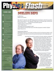
Figure II-1 shows the overall effect seen as the sample gets larger which also usually means<br />
thicker (more mass and more areal density). The curves in Fig II-1 are normalized to unity at<br />
their maximum value. Because the mean free path increases as energy increases, an isotopic<br />
measurement will “see” farther into the item being measured and hence sample more volume and<br />
mass at high energy than at low energy. This means that relative to low energies, large samples<br />
emit more high-energy gamma rays than low energy gamma rays and the relative efficiency<br />
tends to increase with increasing energy more strongly than for small samples. This is illustrated<br />
numerically in Table II-1 for plutonium at low density approximating that of PuO2. The<br />
“thickness” or areal density of the plutonium in a sample must be several mean free paths in<br />
magnitude to take full advantage of the intensity available at a specific measurement energy.<br />
LA-UR-03-4403 2-5
Fig. II-1. The relative efficiency varies for different size samples using the same 16 mm dia x 13<br />
mm deep planar detector. The curves are normalized at their maximum value.<br />
Table II-1. Mean Free Path for Various Gamma Rays in <strong>Plutonium</strong> of Density 3.0 g/cm 3<br />
Pu-238 λ (cm) Pu-239 λ (cm) Pu-240 λ (cm)<br />
152 keV 0.13 129 keV 0.083 104 keV 0.19<br />
766 keV 3.0 414 keV 1.2 160 keV 0.15<br />
642 keV 2.4<br />
Figure II-1 shows that the user can get qualitative information on the plutonium areal density in<br />
the sample just by examination of the shape of the relative efficiency curve.<br />
E. Relative Efficiency Models<br />
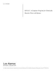
After relative efficiency values have been determined for a specific measurement using eq II-2,<br />
the user has a series of relative efficiency vs energy points that might appear to look like Fig. II-<br />
2. The user then needs to find relative efficiency values for energies not defined by a specific<br />
relative efficiency point and sometimes, even outside the range defined by the relative efficiency<br />
points. This requirement has led to the development of several models to parameterize the<br />
relative efficiency curve.<br />
Fig. II-2. “Raw” relative efficiency points from 239 Pu for a specific measurement.<br />
LA-UR-03-4403 2-6
Several models are discussed in (Sampson 03) including simple models used in early <strong>Los</strong><br />
<strong>Alamos</strong> codes. The models discussed below are more commonly used in modern isotopic<br />
analysis applications.<br />
1. Empirical Model<br />
Fleissner and Ruhter used linear least squares fitting of polynomial expressions in lnE in the<br />
early 1980s to parameterize the relative efficiency vs energy relationship. This represented the<br />
“state of-the-art” when the PANDA chapter on isotopic analysis was drafted.<br />
Fleissner in his GRPAUT software (Fleissner 81a) used the form<br />
2<br />
3<br />
− j<br />
j<br />
∑(<br />
a jEi<br />
) + ( a j+<br />
2 ( ln Ei<br />
) ) + a6δ<br />
6 + 7 7<br />
i = a0<br />
+ ∑<br />
j=<br />
1<br />
j=<br />
1<br />
lnε a δ<br />
(II-3)<br />
in the energy range from 120 keV to above 450 keV with points from 239 Pu, 241 Pu and 241 Am.<br />
The delta function terms, a6 and a7, normalize the 241 Pu and 241 Am data points to the 239 Pu data<br />
points. This form was expanded to include a second relative efficiency curve for cases where<br />
241 Am was not isotopically homogeneous with plutonium.<br />
Ruhter’s form was similar and was used to fit from 120 keV to 210 keV if the spectrum was<br />
limited to that range or 120 keV to 380 keV if the data included the 375-keV region. His<br />
expression was simpler because it was used on a system with limited computing resources.<br />
ln<br />
2or3<br />
∑<br />
j=<br />
1<br />
(<br />
j<br />
ε = a + a δ + a ( ln E ) ) (II-4)<br />
i<br />
0<br />
1<br />
1<br />
j+<br />
1<br />
i<br />
The delta function term, a1 normalizes the 241 Pu data points to the 239 Pu data points. Ruhter did<br />
not use any points from 241 Am to determine efficiency.<br />
All versions of <strong>FRAM</strong> use or have available an empirical relative efficiency curve of<br />
essentially the same polynomial form (Sampson 89). <strong>FRAM</strong>’s empirical relative efficiency is<br />
ln<br />
m<br />
n<br />
j<br />
−1<br />
( C ( ln E ) ) + C δ + C E<br />
3<br />
−2<br />
ε i = C1 + C2Ei<br />
+ ∑ j+<br />
2 i ∑ k+<br />
5 k+<br />
5 ∑ l+<br />
5+<br />
mδ<br />
l+<br />
5+<br />
m i , (II-5)<br />
j=<br />
1<br />
k=<br />
1<br />
l=<br />
1<br />
where the k summation is the normalization for each isotope after the first and the l summation is<br />
the normalization for each additional relative efficiency curve. The <strong>FRAM</strong> empirical relative<br />
efficiency curve is not limited with regard to the number of isotopes (We use as many as 6), nor<br />
is it limited to the number of different relative efficiency curves applied for isotopic<br />
heterogeneity although our principal experience is still with only one additional relative<br />
efficiency curve for isotopic heterogeneity.<br />
All applications of this empirical, polynomial-based relative efficiency curve work very well<br />
over the range of definition. This form can run into trouble if it extrapolated outside its range of<br />
definition or if the relative efficiency data is statistically poor.<br />
2. Physical Model<br />
A physics-based relative efficiency model has been widely used by Gunnink and co-workers at<br />
the Lawrence Livermore <strong>National</strong> Laboratory (Gunnink 90).<br />
LA-UR-03-4403 2-7
where<br />
Cd<br />
1<br />
Pu<br />
2<br />
( − μ ∗ x ) ∗ ( 1−<br />
exp(<br />
− ∗ x ) ∗ eff ∗ ( 1+<br />
bE + cE )<br />
ε j = exp j Cd<br />
μ<br />
Pu<br />
j Pu j<br />
j j , II-6<br />
μ ∗ x<br />
j<br />
Pu<br />
Cd<br />
μ j<br />
Pu<br />
μ j<br />
xCd<br />
xPu<br />
effj<br />
=<br />
=<br />
=<br />
=<br />
=<br />
mass absorption coefficient of cadmium for peak j,<br />
mass absorption coefficient of plutonium for peak j,<br />
thickness (g/cm2) of cadmium absorber,<br />
thickness (g/cm2 of plutonium in the sample,<br />
detector efficiency for peak j from a “generic” efficiency curve,<br />
b, c, = coefficients in a quadratic function to account for small deviations in the<br />
efficiency from the generic value as well as other slowly varying effects,<br />
such as absorption from low Z matrix materials.<br />
This model explicitly accounts for self-absorption in the plutonium in the sample, absorption in<br />
a cadmium filter between the sample and detector, and the intrinsic detector efficiency. It has<br />
been used very successfully in the region from 59 keV to 300 keV with a planar detector. The<br />
variables are determined by iterative non-linear least squares techniques. Because the model is<br />
based on physical principles, it can give valid results outside its range of definition in cases<br />
where simpler models fail.<br />
Vo at <strong>Los</strong> <strong>Alamos</strong> has implemented a very versatile physical model for relative efficiency that<br />
allows for multiple absorbers, multiple efficiency curves, and uses a wide-ranging correction<br />
factor for slowly varying effects.<br />
ε =<br />
μ<br />
∗<br />
Pu<br />
∗ exp<br />
( 1 − exp(<br />
− μ Pu ∗ xPu<br />
)<br />
xPu<br />
( − μ ∗ x ) ∗ exp(<br />
− μ ∗ x ) ∗ exp(<br />
− μ ∗ x )<br />
⎛ c ⎞<br />
⎜ E ⎟<br />
⎝ ⎠<br />
j<br />
( I ) ∗ exp⎜<br />
⎟ ∗ ( Det Eff ) ∗ ( Correction Factor)<br />
i<br />
1<br />
∗<br />
Cd<br />
Cd<br />
Fe<br />
Fe<br />
Pb<br />
Pb<br />
(II-7)<br />
The first term is self absorption in the plutonium; the second line is the absorption in up to<br />
three different materials (out of a choice of seven—Al, Fe, Cd, Er, Pb, H2O, Concrete); Ii is the<br />
activity of isotope i; exp[cj/E] accounts for isotopic heterogeneities (see next section); Det Eff is<br />
a generic detector efficiency parameterized in the software; and Correction Factor corrects for<br />
variations of the actual detector efficiency, nuclear material, and matrix from that specified in the<br />
model. The Correction Factor is a modified Hoerl function.<br />
Correction Factor =<br />
⎛ ⎞<br />
⎜ ∗ ⎟<br />
⎜ ⎟<br />
⎝ ⎠<br />
E<br />
1<br />
b<br />
E c<br />
This physical efficiency function is available in <strong>FRAM</strong> version 4 (Kelley 02) and has been<br />
used in various applications in the energy range from below 40 keV to above 1500 keV.<br />
(II-8)<br />
3. <strong>Isotopic</strong> Heterogeneity<br />
Equation II-1 is very general, but it contains the important assumption that all the measured<br />
isotopes in the sample are homogeneous with respect to each other. Another way of saying this<br />
is that gamma rays of the same energy from different isotopes must suffer the same attenuation<br />
as they escape from the sample. Failure of this assumption is called isotopic heterogeneity.<br />
LA-UR-03-4403 2-8
An example of isotopic heterogeneity occurs in pyrochemical plutonium processing<br />
applications. This process produces pure plutonium metal with Am and U removed. The waste<br />
Am and U that have been separated reside as a chloride salt along with small amounts of residual<br />
plutonium as metal fines in the residue stream. The proper quantification by calorimetric assay<br />
of the plutonium in this residue stream is complicated by the isotopic heterogeneity of the<br />
plutonium and americium present. The gamma rays from 241 Am suffer attenuation<br />
predominately in a low-Z chloride salt matrix while the plutonium gamma rays suffer attenuation<br />
characteristic of the high-Z plutonium metal fines. The relative-efficiency curve for gamma rays<br />
from 241 Am is different than that from plutonium. The isotopic ratio expression of eq. II-1 does<br />
not work in this instance.<br />
Fleissner first proposed a second relative efficiency curve for 241 Am in pyrochemical<br />
residues—the 241 Am curve being related to the main plutonium relative efficiency by a<br />
multiplicative factor of exp[β/E], E being energy and β being a fitted constant . The Empirical<br />
(Eq. II-5) and Physical (Eq. II-7) relative efficiency formalisms contained in version 4 of <strong>FRAM</strong><br />
both include a heterogeneity terms as proposed by Fleissner.<br />
Testing of this heterogeneous model has involved comparison of isotopic measurements on<br />
heterogeneous pyrochemical residues with destructive chemical analysis of the entire item<br />
(Sampson 89). These destructive chemical analysis studies are very lengthy and extremely<br />
expensive so comparison data is limited. The most important parameter determined in the<br />
isotopic measurement is Peff in mW/gPu. This is used directly to convert a calorimetry<br />
measurement of total sample power to grams elemental plutonium. With the heterogeneous<br />
relative-efficiency model of Fleissner, both Fleissner’s GRPAUT code and the <strong>Los</strong> <strong>Alamos</strong><br />
<strong>FRAM</strong> code determined Peff with a bias that usually did not exceed 5%. <strong>Analysis</strong> of the same<br />
data without the heterogeneous relative-efficiency correction yielded biases from 10% to 200%.<br />
III. <strong>PC</strong>/<strong>FRAM</strong><br />
A. Development<br />
The first version of <strong>FRAM</strong> (Sampson 89) was fielded in 1988 at the <strong>Los</strong> <strong>Alamos</strong> <strong>Plutonium</strong><br />
Facility running on Digital Equipment Corporation MicroVAX computers. The <strong>FRAM</strong> code<br />
represented a major advance in measurement flexibility as it was designed to address the<br />
shortcomings of the software described in PANDA and also included significant upgrades in the<br />
measurement and analysis hardware to the state of the art at that time.<br />
By the early 1990s, computer hardware and software developments made the VAX/VMSbased<br />
system obsolete. The program was recoded in C to operate on a <strong>PC</strong> under Windows 3.1.<br />
This advance was necessary to open up the applications for the <strong>FRAM</strong> code (now called<br />
<strong>PC</strong>/<strong>FRAM</strong>) at facilities that did not support the previous VAX system. This change has resulted<br />
in <strong>FRAM</strong> becoming commercially available through several vendors and now being used<br />
worldwide. Some of the major features of <strong>FRAM</strong> are described below. [Note: We use the<br />
names <strong>PC</strong>/<strong>FRAM</strong> and <strong>FRAM</strong> interchangeably throughout this document.]<br />
B. Single Detector System<br />
Like all previous <strong>Los</strong> <strong>Alamos</strong> isotopic analysis systems, <strong>PC</strong>/<strong>FRAM</strong> uses only a single detector<br />
to acquire its data. We made a conscious choice to keep <strong>PC</strong>/<strong>FRAM</strong> a single detector system<br />
because single detector systems are inherently<br />
• Easier to use<br />
• More versatile<br />
• More reliable<br />
• Less expensive<br />
• Occupy less facility space<br />
LA-UR-03-4403 2-9
C. Choice of Detector Type<br />
<strong>PC</strong>/<strong>FRAM</strong> is the only isotopic analysis software system that can obtain a complete isotopic<br />
analysis using either a single planar, a single coaxial HPGe detector, or a CdTe detector.<br />
When using the traditional single planar detector, <strong>PC</strong>/<strong>FRAM</strong> has most often been used to<br />
collect and analyze data in the 120–420 keV range. <strong>PC</strong>/<strong>FRAM</strong> has been used with a single<br />
planar detector to measure uranium isotopic composition in the energy range from 120–1024<br />
keV. Recent developments fielded in version 4 of <strong>PC</strong>/<strong>FRAM</strong> now allow the analysis of planar<br />
detector spectra in the 100-keV region and the 40-keV region (Vo 01a).<br />
The most widely used mode of operation with a single coaxial detector is to acquire a<br />
spectrum from 0–1024 keV. Various analysis modes can then be used. If the region between<br />
120 and 200 keV is available, <strong>PC</strong>/<strong>FRAM</strong> will work best analyzing from 120–450 keV. When<br />
analysis below 200 keV is precluded (sample shielding or thick-walled sample container)<br />
<strong>PC</strong>/<strong>FRAM</strong> can still obtain a complete isotopic analysis using only gamma rays above 200 keV<br />
from a single coaxial detector spectrum. A complete analysis (all measurable isotopes) using<br />
only gamma rays above 300 keV is also possible. We have also found that the optimum analysis<br />
of coaxial detector data from some samples may come from the 200–800 keV region even when<br />
the region between 120 and 200 keV is available.<br />
The optimum choice of planar or coaxial detectors is made only after considering all possible<br />
measurement applications. The planar detector is usually chosen if all measured items are<br />
unshielded or contained in “thin” containers. If shielded containers, thick-walled containers or a<br />
mixture of thin and thick/shielded containers are encountered, then a coaxial detector system is<br />
optimum. <strong>PC</strong>/<strong>FRAM</strong> is the only available isotopic analysis method using a coaxial detector in<br />
the energy range from 120–300 keV.<br />
With a CdTe detector, one collects data in the 125-414 keV range, just like a planar HPGe.<br />
D. Shielded Samples<br />
Most isotopic analysis codes (including the original Vax-based <strong>FRAM</strong>) require the presence of<br />
spectral peaks in the region below 200 keV, regardless of whether they use one or two detectors.<br />
When this region is not available, perhaps because the sample is shielded to lower radiation<br />
exposure or because it is inside a very heavy-walled container, some isotopic analysis codes may<br />
not function. <strong>PC</strong>/<strong>FRAM</strong> was the first code to demonstrate the ability to make measurements<br />
through thick-walled containers or on shielded samples. Any software that obtains its results<br />
from gamma rays and x rays in the region around 100 keV is easily defeated by as little as a few<br />
tenths of a mm of lead or about 10 mm of steel. <strong>FRAM</strong> measurements have been made through<br />
as much as 25 mm of lead and very easily through 25 mm of steel.<br />
E. Uranium <strong>Isotopic</strong> <strong>Analysis</strong><br />
Up until 1990 the isotopic analysis techniques originally proposed by Parker and Reilly were<br />
applied only to plutonium. There was always the need for uranium isotopic analysis but the<br />
features of the uranium gamma-ray spectrum precluded the easy application of the “peak pair”<br />
ratio method used in early isotopic analysis applications.<br />
The uranium gamma-ray spectrum is essentially divided into two regions. The low-energy<br />
region up to about 200 keV contains only gamma rays from 235 U with the major gamma rays at<br />
143.76, 163.33, 185.72, 202.11, and 205.31 keV, all from 235 U. The sole gamma ray from 234 U<br />
above 100 keV is at 120.90 keV and 236 U has no measurable gamma rays. The intense 238 U<br />
gamma rays arise from its 234m Pa daughter with energies of 742.81, 766.36, 786.27, and 1001.03<br />
keV. The wide separation between 235 U and 238 U gamma rays stymied the application of the<br />
early arbitrary-sample isotopic analysis techniques. The weak 234m Pa gamma ray at 258.26 keV<br />
plays an important role in current applications of <strong>FRAM</strong> to uranium.<br />
LA-UR-03-4403 2-10
The formalism of <strong>FRAM</strong> does not require closely spaced peak pairs. Thus, in the late 1980s,<br />
we applied the original VAX version of <strong>FRAM</strong> to analyze uranium. This required a coaxial<br />
detector and data analysis in the 120-1200 keV region. We demonstrated <strong>FRAM</strong>’s ability to<br />
measure, with no code modification, the 238 U/ 235 U ratio in samples of arbitrary physical and<br />
chemical composition, geometry, and mass, containing only uranium.<br />
In <strong>PC</strong>/<strong>FRAM</strong>, uranium analysis was expanded to include 234 U and in the latest version we<br />
include a correlation to predict 236 U and a correction for cases where 234m Pa is not in equilibrium.<br />
F. Version 4<br />
Sampson (Sampson 03) describes the features and improvements in all of the released versions<br />
of <strong>FRAM</strong>. The features and upgrades in the most recent release, version 4, mainly concern<br />
enhancements to the physics algorithms, new measurement capabilities, and a new structure to<br />
make derivative applications easier to implement.<br />
Version 4.2<br />
• Relative Efficiency. This version incorporates a new physical model for calculating<br />
the relative efficiency curve.<br />
• <strong>Analysis</strong> Engine. The analysis algorithms have been placed in their own library.<br />
This makes it easier for other users to adapt <strong>FRAM</strong> for their own applications.<br />
• New Menus for Uranium <strong>Analysis</strong>. There are separate dialog boxes for measuring<br />
plutonium and uranium and for analyzing Pu and U data files.<br />
• Intelligence. There is a selectable capability of automatically switching, in a limited<br />
way, from one parameter set to another depending on analysis results.<br />
• Uranium <strong>Analysis</strong> Enhancements. Enhancements for uranium analysis include 1)<br />
correction for 234 Th nonequilibrium, 2) isotopic correlation to predict 236 U, and 3)<br />
corrections for coincidence summing effects.<br />
• CdTe. <strong>FRAM</strong> can analyze spectra taken with a CdTe detector in the 120-414 keV<br />
energy range (Vo 02).<br />
• 100-keV Region <strong>Analysis</strong>. <strong>FRAM</strong> can analyze plutonium using the 100-keV region<br />
(Vo 01a).<br />
• 40-keV Region <strong>Analysis</strong>. <strong>FRAM</strong> can analyze freshly separated plutonium using the<br />
40-keV region (Vo 01a).<br />
IV. HOW <strong>FRAM</strong> WORKS<br />
A. Obtain Data<br />
There are two basic types of data sources for <strong>FRAM</strong>.<br />
1) “Live” data from a multichannel analyzer (MCA) acquiring a gamma-ray spectrum from a<br />
high-resolution detector (usually HPGe). <strong>FRAM</strong> can control the data acquisition from several<br />
commercial MCA families. The ORTEC line of Multichannel Buffers (MCB) operating with the<br />
Maestro MCA emulator can all be controlled via <strong>FRAM</strong>. Canberra MCAs operating under<br />
Genie 2000 can also be controlled from <strong>FRAM</strong>. Control is limited to the basic functions of<br />
count time, start, stop, and readout to a disk file. The user must invoke the appropriate MCA<br />
emulator other functions (high voltage, amplifier gain, etc.). The analysis of "live" data acquired<br />
under <strong>FRAM</strong> control proceeds automatically after the acquisition terminates.<br />
2) Data from a disk file. <strong>FRAM</strong> can read and analyze data from disk files recorded in several<br />
data formats. These data formats include, for version 4, the following formats:<br />
LA-UR-03-4403 2-11
• N-1 standard<br />
• Canberra S100<br />
• Ortec ‘spc’<br />
• Ortec ‘chn’<br />
• Canberra CAM<br />
• IAEA MCRS<br />
• IAEA MMCA<br />
• Green Star<br />
• ASCII<br />
If <strong>FRAM</strong> is purchased from a licensee it will contain only the control and data formats<br />
appropriate to the vendor’s own products or that are publicly available. In a version of <strong>FRAM</strong><br />
from <strong>Los</strong> <strong>Alamos</strong>, the user will have access to everything that was current at the version release<br />
date. The user will have to purchase and install the appropriate MCA emulator to control the<br />
setup of the MCA and make full use of the commercial formats.<br />
B. Perform <strong>Analysis</strong><br />
The analysis of a gamma-ray pulse-height spectrum by the <strong>PC</strong>/<strong>FRAM</strong> code proceeds in two<br />
steps, 1) the internal calibration, and 2) the analysis of the spectral data.<br />
1. Internal Calibrations<br />
The internal calibration uses peaks in the spectrum under analysis to provide a calibration of<br />
energy vs. channel, full width at half maximum (FWHM) vs. channel, and peak shape (tailing<br />
parameters) vs. channel. These calibrations do not depend on parameters determined from other<br />
measurements that may have been taken with different conditions of count rate, resolution, or<br />
electronic adjustment. In some cases, there are insufficient peaks to use the unknown spectrum<br />
for its own calibrations. In these cases, one can fix the peak calibration parameters to their initial<br />
values in the parameter set.<br />
a. Energy Calibration<br />
The first portion of the internal procedure calibrates energy vs. channel number from a list of<br />
calibration peaks in the parameter set. A piecewise linear calibration is made between<br />
successive pairs of peaks. The algorithm locates the peak at the maximum count found in a<br />
region of 10 channels on either side of the default peak position located using the default gain<br />
and zero values from the parameter set. <strong>FRAM</strong> is not constrained to any particular energy<br />
calibration. Within the constraints of spectral quality, <strong>FRAM</strong> can analyze spectra at any gain<br />
given that the energy calibration is known well enough to find the calibration peaks within a ± 10<br />
channel window. The peak centroid is found using a least-squares fit of a quadratic function to<br />
the logarithm of the counts. Calibration outside the range of the energy calibration list is linearly<br />
extrapolated from the nearest two points.<br />
b. Initial Background<br />
Next, a background is calculated for all peak regions in the parameter set. The calculation uses<br />
the background functional shape for each region that is specified in the parameter set.<br />
c. FWHM Calibration<br />
The parameter set contains a user-editable list of peaks for use in the internal calibration of<br />
FWHM vs. energy. The FWHM of each peak in the list is calculated after a channel-by-channel<br />
subtraction of the initial background. The FWHM is calculated from a least-squares fit of a<br />
quadratic to the logarithm of the net counts over a range of channels in which the counts exceed<br />
LA-UR-03-4403 2-12
75% of the peak maximum on the low-energy side and 25% of the peak maximum on the highenergy<br />
side (for CdTe, because of the larger tails, the fit starts from 85% on the low-energy side).<br />
The FWHM as a function of energy that is used in calculating the response function for an<br />
arbitrary fitted peak is found from a least squares fit to the function:<br />
FWHM<br />
⎡<br />
⎛ A<br />
⎤<br />
( E)<br />
= SQRT<br />
⎢⎣<br />
A + ( A ∗ E)<br />
+ 3 ⎜ ⎟<br />
⎞<br />
1 2<br />
⎝ E⎠⎥<br />
(IV-1)<br />
⎦<br />
The first two terms are physics-based while the third term accounts for the observation that the<br />
FWHM for some detectors tends to “level out” at low energies.<br />
d. Peak Shape/Tailing Calibration<br />
The gamma-ray peak shape is described by a central Gaussian component with a single<br />
exponential tail on the low-energy side of the peak.<br />
2<br />
Y ( J)<br />
= Ht ∗exp[<br />
α ∗(<br />
J − x0<br />
) ] + Tail(<br />
J)<br />
, (IV-2)<br />
where<br />
Y(J) = Net counts in channel J,<br />
Ht<br />
α<br />
=<br />
=<br />
Peak height at the peak centroid x0,<br />
2.77259/FWHM 2 is the peak width parameter,<br />
and the tailing parameter Tail(J) is given by<br />
[ ( ) ]<br />
2<br />
= Ht ∗exp[<br />
( T1<br />
+ T2<br />
∗ E)<br />
+ ( T3<br />
+ T4<br />
∗ E)<br />
∗(<br />
J − x ) ] ∗ 1−<br />
exp − 0.<br />
4 ∗α<br />
∗(<br />
J ) . (IV-3)<br />
Tail( J)<br />
− x<br />
Both the amplitude and slope of the tailing function are permitted to be a function of energy.<br />
However, in practice, we set T4 to zero reducing the number of unknowns to three. After<br />
subtracting the Gaussian portion of the peak (known because we have calibrations for energy and<br />
FWHM), we combine the data from all the FWHM peaks using the net channel contents on the<br />
low energy side of the peak from 0.5 to 1.5 FWHM from the peak center to determine the slope<br />
and amplitude constants from a least-squares fit.<br />
This completes the internal calibration giving all the parameters necessary to calculate the<br />
shape of a gamma-ray peak at any location in the spectrum.<br />
2. <strong>Analysis</strong> of Spectral Data<br />
After the internal calibration is complete, the analysis proceeds on a region-by-region basis in<br />
the order that the regions are entered in the parameter set. The program makes three iterations<br />
through all the regions. A very detailed description of the analysis procedure may be found in<br />
(Kelley 02, Sampson 03).<br />
The analysis starts by subtracting the initial background to get the net counts in a region. The<br />
background for the first iteration was calculated during the internal calibration phase. The<br />
analysis is iterative because of the interdependence of the peak areas and relative efficiencies<br />
calculated in separate steps.<br />
a. Calculate Peak Areas <strong>Using</strong> Response Functions<br />
For each of the regions defined in the parameter set, <strong>FRAM</strong> calculates the peak areas using<br />
response functions. The procedure allows peak areas to be fixed to peaks within or outside of<br />
the region. The results obtained after the final iteration consist of peak areas and uncertainties<br />
for all of the peaks in each region.<br />
LA-UR-03-4403 2-13<br />
0<br />
0
. Calculate Relative Efficiencies<br />
Relative efficiencies are calculated for all of the designated relative efficiency peaks in the<br />
parameter set. The individual relative efficiency points are fit via least squares to either the<br />
empirical relative efficiency function (Eq. II-5) or the physical relative efficiency function (Eq. II-7).<br />
The empirical function is fit by linear least squares methods while the physical relative efficiency<br />
function is determined by non-linear least squares using the Levenberg-Marquardt method.<br />
c. Calculate Relative Activities<br />
The relative activities are calculated for each peak by summing over all of the isotopes that<br />
contribute to the peak. Some of the peaks from the decay of the 237 U daughter of 241 Pu also<br />
contain an unresolved (exact energy match) gamma ray from 241 Am. The model is:<br />
Areai = ∑ A j ( BRij<br />
)( REi<br />
) , (IV-4)<br />
where,<br />
j<br />
A j is the activity ratio for the jth isotope,<br />
BR ij is the branching ratio for the gamma ray emitted by the jth isotope contributing to<br />
the area of the ith photopeak<br />
RE is the relative efficiency at the energy of the ith peak<br />
i<br />
The relative activities, the half lives, and atomic masses of the isotopes are then combined to<br />
yield the relative masses for each isotope.<br />
d. Calculate <strong>Isotopic</strong> Fractions<br />
After the third iteration is complete, the final relative masses (relative to the first isotope in the<br />
isotope list) are combined to give the absolute isotopic fractions without 242 Pu ( 236 U). The<br />
fractions are renormalized accounting for 242 Pu ( 236 U) computed by correlation or fixed by<br />
operator entry. Non-plutonium (uranium) isotopes are quantified relative to total plutonium<br />
(uranium). For samples containing no plutonium or uranium, the final results are the relative<br />
masses themselves. Auxiliary results such as the effective specific power and effective 240 Pu<br />
fraction are computed from the plutonium isotopic fractions and the appropriate constants in the<br />
parameter set.<br />
e. Calculate <strong>Isotopic</strong> Correlation for 242 Pu and 236 U<br />
<strong>Plutonium</strong>-242 and 236 U cannot be measured directly with gamma-ray spectroscopy techniques.<br />
It is customary to introduce an empirical isotopic correlation (Gunnink 90, Bignan 95) to predict<br />
their concentrations from the measured ratios for the other isotopes.<br />
<strong>FRAM</strong> predicts 242 Pu from:<br />
242<br />
238 B 239 C 240 D 241 241 E<br />
[ ( Pu)<br />
× ( Pu)<br />
× ( Pu)<br />
× ( Pu+<br />
Am)<br />
]<br />
Pu = A×<br />
(IV-4)<br />
where the five constants, A–E, are user-editable values in the parameter file.<br />
In a similar manner, Vo has developed a correlation to predict 236 U in uranium-bearing<br />
samples. It is of the form<br />
236<br />
235 B 238 C<br />
[ ( U ) × ( U ) ]<br />
U = A×<br />
(IV-5)<br />
LA-UR-03-4403 2-14
The constants in eq. IV-5 have been determined from mass spectrometry values for US uranium<br />
produced by the gaseous diffusion process.<br />
V. PARAMETER FILES, THE KEY TO <strong>FRAM</strong>’S VERSATILITY<br />
The <strong>FRAM</strong> code has been structured to give the user as much control as desired over the<br />
analysis to increase versatility and applicability. This is accomplished by using Parameter Files<br />
(or Parameter Sets). A Parameter File contains the all the parameters required to analyze a<br />
gamma-ray spectrum. This includes information on the isotopes to be analyzed, the gamma-ray<br />
peaks to use, the nuclear data for the isotopes and gamma-rays, data acquisition conditions such<br />
as gain, zero, number of channels, spectral regions to analyze, and diagnostic test parameters.<br />
These parameters reside in a custom-designed database within <strong>FRAM</strong>. This database can<br />
accommodate multiple parameter sets. The Change Parameter Utility, accessed from <strong>FRAM</strong>,<br />
gives the user access to all sets. The utility allows the user to add a new parameter set, delete a<br />
set, or modify the values in any set. The utility also allows the user to export the information in a<br />
parameter set to a text file on disk and subsequently to import this information back into the<br />
database allowing different systems to share parameter sets. Formally, “parameter set” refers to<br />
the information residing in the database in computer memory. “Parameter file” refers to the<br />
information in a text file residing on a disk.<br />
<strong>FRAM</strong> is delivered with a variety of parameter files suitable for nearly all routine analyses.<br />
These parameter files usually do not need editing or changes to use <strong>FRAM</strong> for the first time.<br />
Routine <strong>FRAM</strong> analyses can be started with as few as three mouse clicks.<br />
VI. <strong>FRAM</strong> USER INTERFACE<br />
The <strong>FRAM</strong> user interface for version 4.2 provides a wide range of options governing data<br />
acquisition, data analysis, data display, results output, and parameter set manipulation and<br />
editing. We will briefly illustrate the extensive capability available to the user of <strong>FRAM</strong>.<br />
The main menu of <strong>FRAM</strong> appears with four major options, File, Edit, Measure, and Options.<br />
A. File<br />
The File option allows the user to open a spectral data file where it can be viewed under<br />
Options. The file can also be saved in any of the supported data formats. Saving the file in the<br />
ASCII text format makes it easy to plot the data in most graphical applications.<br />
B. Edit<br />
The Edit menu has three groups of options. The first group allows password-protected access<br />
to the Change Parameter Utility. It also contains General Defaults allowing the user to set up<br />
LA-UR-03-4403 2-15
global parameters that govern the data handling in the system such as default paths for accessing<br />
<strong>FRAM</strong>, storing the spectral data and results files, and access to supported MCAs.<br />
The second group of parameters under the Edit menu allows the user to set up default entries in<br />
many of the application windows. With the use of these defaults, the user is able to start a<br />
measurement with only three clicks of the mouse.<br />
The third group is the password-protected User List. The User List controls access at three<br />
levels of password protection to all of the password-protected options.<br />
C. Measure<br />
The Measure menu governs the acquisition and analysis of data from both “live” MCA sources<br />
and disk files.<br />
The Acquire Data option controls acquisition of data from a supported MCA and the storage of<br />
the data (without analysis) in a disk file. The Measure Pu (U) Sample options follow the data<br />
acquisition with an immediate analysis of the acquired spectrum. Analyze Pu (U) Data analyzes<br />
the spectral data from an existing disk file. The Measure Pu Sample window appears below as<br />
an example.<br />
Only REQUIRED entry<br />
The window above has some of the entries defaulted from the Edit | Measure Pu Sample<br />
Defaults option. At this point the only entry required to start the measurement and complete the<br />
analysis is the Sample ID. With the use of defaults successive measurements may be completed<br />
with only identification of the sample and clicking the Start button. In many cases the user will<br />
also want to utilize some of the optional output options. To facilitate this, the Sample ID is<br />
defaulted as the filename for data storage.<br />
LA-UR-03-4403 2-16
D. Options<br />
The Options menu allows the user several ways to display and view the spectral data and the<br />
results of the analysis. The entire spectrum can be displayed and manipulated from the Plot<br />
Spectrum option with versatility similar to that of a commercial MCA emulator. The user can<br />
also display the peak fits and view the relative efficiency curve (below). These options are<br />
invaluable when troubleshooting<br />
a suspect analysis. The results of<br />
selecting Plot Efficiencies and<br />
Display Fits are shown below<br />
with fits being displayed showing<br />
only the fit envelope (left) or with<br />
the individual components (right).<br />
The ISOPOW option gives<br />
access to a plutonium and<br />
americium decay correction<br />
program (Sampson 86a) that can<br />
be used on line or off line.<br />
LA-UR-03-4403 2-17<br />
The option Language under the Options menu<br />
allows the user to display the operator interface,<br />
<strong>FRAM</strong> program messages, and results in a<br />
language other than English. The language<br />
strings are kept in a text file allowing any<br />
European language to be used as the second<br />
language merely by editing the second language<br />
text file. The current second language used with
<strong>FRAM</strong> is Russian. When Russian is selected the Main menu with “Options” pulled down looks<br />
like the screen to the left. The user can switch between the two languages with a single mouse<br />
click.<br />
VII. <strong>FRAM</strong> PERFORMANCE<br />
A. Measurement Precision or Repeatability<br />
1. Definitions<br />
In this section, we describe the many interrelated factors that govern the statistical precision of<br />
an isotopic measurement. In this context, precision or repeatability refer to the variability arising<br />
from counting statistics and are usually denoted by the relative standard deviation (RSD) in per<br />
cent.<br />
sigma<br />
% RSD = 100×<br />
. (VII-1)<br />
measured value<br />
Here sigma is the absolute standard deviation of the measured value.<br />
Sigma can be determined in at least two ways. First, the sigma from counting statistics is<br />
estimated within <strong>FRAM</strong> using standard error propagation techniques. This is difficult given<br />
mathematical analysis involved, the presence of correlated variables, and the wide range of the<br />
magnitude of the measured values. However, this method gives an estimate of sigma for every<br />
measurement and is invaluable when one has only a single measurement. The second method<br />
uses repeated measurements. From n repeated measurements of the variable x, we determine s,<br />
the standard deviation of the sample and use it as an estimate of the standard deviation of the<br />
population.<br />
n<br />
2 1 ( s ) = (<br />
∑ − x<br />
n − 1<br />
1<br />
)<br />
2<br />
i x<br />
(VII-2)<br />
This expression is useful when comparing the estimated standard deviation with the standard<br />
deviation (eq VII-2) observed from repeated measurements. One has to perform many repeated<br />
measurements to verify propagated error estimates accurately as Table VI-1 illustrates.<br />
Sigma estimated in this fashion is also a random variable. That is, if the series of n<br />
measurements of x is repeated, s will be different. The mean value of s will be the population<br />
sigma. The relative standard deviation of s values is given by the formula<br />
( )<br />
1<br />
RSD s =<br />
(VII-3)<br />
2(<br />
n − 1)<br />
Table VII-1 The RSD of Sigma (Error of the Error)<br />
No. of<br />
Measurements<br />
RSD of Sigma<br />
10 0.235<br />
15 0.189<br />
25 0.144<br />
50 0.101<br />
LA-UR-03-4403 2-18
2. Influencing Factors<br />
In this section we will discuss some of the many, often interrelated factors, which influence the<br />
precision or repeatability of the isotopic measurement.<br />
a. Count Rate and Throughput<br />
The net counts in the photopeaks of the analyzed spectrum are the primary factors determining<br />
the measurement precision. The count rate directly influences the net photopeak counts. While<br />
the count rate in the detector is the parameter that is often observed, it is the actual data storage<br />
rate in the MCA that is of direct importance; this depends upon electronics settings including<br />
shaping time and the use of pulse-pileup rejection. Measurement systems are usually optimized<br />
by simultaneously measuring the throughput and resolution vs. incoming count rate and choosing<br />
the compromise settings best for the application at hand. An excellent discussion of these<br />
compromises may be found in (Parker 91a).<br />
Throughput curves show a maximum throughput rate beyond which throughput decreases and<br />
counting precision worsens. The best compromise for throughput and resolution is usually<br />
chosen to be at a counting rate significantly below the throughput maximum. Operating at input<br />
counting rates that are 50-60 % of the count rate at the throughput maximum usually yields<br />
throughput values that 80-90 % of maximum while simultaneously preserving detector<br />
resolution.<br />
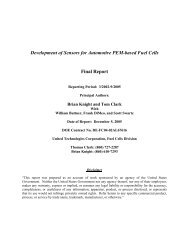
Figure VII-1 shows the throughput and resolution measured with a 25% relative efficiency<br />
coaxial HPGe detector coupled with first generation digital signal processing electronics<br />
operated with a rise time of 4μs (equivalent to a 2μs shaping time in an analog amplifier). Here<br />
the throughput maximum occurs at an input rate of 60 kcps but we usually choose to operate at a<br />
maximum input rate of around 40 kcps where the resolution is better.<br />
Optimizations performed in this manner affect the primary results of an isotopic analysis<br />
measurement. Figure VII-2 shows how the precision of the <strong>FRAM</strong> result for 240 Pu and Peff varies<br />
for the same data set presented in Figure VII-1. Collection of spectral data at an input rate of 40<br />
kcps gives essentially the same precision as operating at the 60 kcps peak of the throughput<br />
curve. The precision does not change very rapidly in a broad range about the throughput<br />
maximum, but it does worsen significantly at low count rates. In the range where the throughput<br />
curve is linear at rates below 15 kcps, the precision varies with the square root of the number of<br />
counts.<br />
LA-UR-03-4403 2-19<br />
Fig. VII-1. Throughput<br />
and resolution for 208<br />
keV peak of 241 Pu- 237 U<br />
from 965 g PuO2 with<br />
16.85 % 240 Pu,and a<br />
25%-relative-efficiency<br />
HPGe detector.
Fig.VII-2. % RSD of <strong>FRAM</strong><br />
measurement of 240 Pu and Peff for<br />
965 g PuO2 with 16.85 % 240 Pu, a<br />
25%-relative-efficiency HPGe<br />
detector, an ORTEC DSpec<br />
operated at 4-μs rise time with<br />
analysis in the 120-450 keV<br />
region. Count time was 1 hour.<br />
b. Electronic Settings<br />
The amplifier shaping time is the single most influential electronic setting affecting system<br />
performance. The shaping time-resolution tradeoff is well known and is discussed in detail by<br />
Parker (Parker 91a). The term “rise time” is usually used in characterizing digital spectroscopy<br />
systems with the rise time being about three times the analog shaping time. Throughput<br />
generally varies inversely with shaping time. A shorter shaping time improves throughput.<br />
Longer shaping times usually correspond to better resolution and lower throughput, although<br />
for any specific system, the user will find that the resolution-shaping time curve goes through a<br />
broad minimum that is dependent upon the type of detector being characterized. One always<br />
operates on the low or shorter shaping time side of this minimum, giving up a little resolution in<br />
order to improve throughput. Fortunately the minimum is broad and resolution does not suffer<br />
too much.<br />
For the small coaxial detectors (25-30 % relative efficiency) often used with <strong>FRAM</strong>, we obtain<br />
good results with analog systems using 2-μs Gaussian or triangular shaping. This corresponds to<br />
a rise time of 4 μs for digital systems. With these settings, good resolution is obtained at<br />
suggested maximum count rates of approximately 30 kcps (analog) and 40 kcps (digital).<br />
For the planar detectors most often used with <strong>FRAM</strong> (16-25 mm dia. by 13-15 mm deep), we<br />
recommend a 1-μs triangular shaping with an analog system or a 2-μs rise time with a digital<br />
system.<br />
Since the first <strong>Los</strong> <strong>Alamos</strong> isotopic systems in the early 1980s, improvements in amplifiers<br />
and pulse processing methods have led to improvements of about a factor of 3 in the precision<br />
for 240 Pu or Peff for measurements with the same count time.<br />
c. Count Time<br />
Poisson counting statistics are an appropriate model to represent the influence of counting time<br />
on the precision of isotopic analysis measurements. That is, the % RSD of a measured isotopic<br />
fraction varies inversely with the square root of the counting time, T.<br />
1<br />
% RSD ≈ (VII-4)<br />
T<br />
Increasing the counting time by a factor of 2 improves the % RSD by a factor of 1.4.<br />
LA-UR-03-4403 2-20
d. Energy Range<br />
The energy range used in the analysis is often the single largest factor in determining the<br />
precision or repeatability of an isotopic measurement. The foremost factor here is the intrinsic<br />
intensity of the gamma rays used in the analysis. Table VII-2 displays the intensities for the<br />
principal gamma rays from each of four energy regions that have been used historically. The<br />
intensities of the principal gamma rays from the isotopes 238 Pu and 240 Pu drop by roughly an<br />
order of magnitude with each successively higher energy region. This means that the best<br />
precision measurements, at least for the important 240 Pu and 238 Pu isotopes, come from the lowest<br />
energy regions.<br />
The 40–60 keV energy region is used only in the special case of freshly reprocessed ( 241 Am<br />
and 237 U removed) plutonium-bearing solutions, mainly in reprocessing plants. This region is<br />
not used widely for isotopic analysis because the Compton continuum from the 59.5-keV 241 Am<br />
peak swamps the plutonium peaks in the 40-keV region for aged materials and these low energy<br />
gamma rays are easily absorbed by many types of containers.<br />
Table VII-2 Intrinsic Gamma-Ray Intensities of Major Gamma Rays in Principal Energy<br />
Regions<br />
Region<br />
238<br />
Pu<br />
239<br />
Pu<br />
240<br />
Pu<br />
241 237<br />
Pu- U(*)<br />
241<br />
Am<br />
(keV) (keV) γ/s/g (keV) γ/s/g (keV) γ/s/g (keV) γ/s/g (keV) γ/s/g<br />
40–60 43.5 2.5 e8 51.6 6.2 e5 45.2 3.8 e6 59.5 4.5<br />
90– 99.9 4.6 e7 98.8 2.8 e4 104.2 5.9 e5 103.7 3.9 e6 98.9 2.6 e7<br />
103.0 2.5 e7<br />
120– 152.7 6.1 e6 129.3 1.4 e5 160.3 3.4 e4 148.6 7.2 e6 125.3 5.2 e6<br />
375.0 3.6 e4 *208.0 2.0 e7 335.4 6.3 e5<br />
413.7 3.4 e4 *332.4 1.1 e6<br />
450– 766.4 1.4 e5 646.0 3.4 e2 642.5 1.0 e3 662.4 4.6 e5<br />
722.0 2.5 e5<br />
The 90–105 keV region has been widely used for isotopic analysis and often offers the best<br />
precision for the measurement of 240 Pu. Strong attenuation of these low energy gamma rays does<br />
preclude their use for samples in thick-walled or shielded containers. An absorber of 10 mm of<br />
steel is usually enough to stop measurements using this region.<br />
The 120–450 keV region is the most versatile region for plutonium isotopic analysis and is<br />
historically the region used at <strong>Los</strong> <strong>Alamos</strong>. Measurement precision for 240 Pu in the 120–450 keV<br />
region is usually poorer than in the 100-keV region. The advantage of this region is that<br />
measurements can easily be performed through as much as 12 mm of steel and even 0.3 mm of<br />
lead.<br />
<strong>FRAM</strong> was the first code to carry out a complete Pu isotopic analysis using the 200–800 keV<br />
region. This capability allows measurements on samples in heavy-walled containers or in<br />
containers with internal shielding that prevents gamma rays below 200 keV from reaching the<br />
detector. Variants of this allow a complete plutonium isotopic analysis through shielding up to<br />
25 mm of lead (Hypes 00).<br />
The ability to analyze the 200-800 keV region for the complete isotopic distribution gives<br />
<strong>FRAM</strong> several more options for the analysis of large samples. The inherent advantage in<br />
precision of the 100-keV energy region for 240 Pu and 238 Pu analysis is reduced for large samples<br />
analyzed at high energy because of the increased penetrability of gamma rays in the 600-800<br />
LA-UR-03-4403 2-21
keV range relative to the 100-keV gamma rays. In effect, the high-energy gamma rays sample a<br />
larger volume of the sample. This increased penetrability is apparent principally for items with<br />
larger areal plutonium densities. Table VII-3 shows the parameters that affect penetrability for<br />
the three 240 Pu gamma rays at 104, 160, and 642 keV. This is the effect causing the relative<br />
efficiency curves for large items to increase in magnitude as one moves to higher energies (see<br />
Fig. II-1).<br />
Table VII-3 Absorption Properties for PuO2 at ρ = 3g/cm 3 for Gamma Rays from 240 Pu<br />
Energy<br />
μ/ρ<br />
(keV)<br />
(cm 2 μ<br />
/g)<br />
(cm -1 Mean Free Path<br />
)<br />
(cm)<br />
104 1.62 4.9 0.21<br />
160 2.01 6.0 0.17<br />
642 0.131 0.39 2.5<br />
The self-absorption at 160 keV is actually greater than at 104 keV because the plutonium K<br />
edge falls at 121.8 keV, between the two energies. The mean free path (mfp) at 642 keV is 15x<br />
greater than at 160 keV. Samples with a thickness greater than three mfp at 642 keV will have<br />
an emission rate increase at 642 keV over that at 160 keV that nearly compensates for the<br />
intrinsic intensity(γ/s/g) difference (Table VII-2) at the two energies. When this is coupled with<br />
the lower background continuum present at higher energies, one often obtains better precision for<br />
measurement of 240 Pu at 642 keV than at 160 keV.<br />
Another consideration for using the 200–800 keV range for larger samples is that one is often<br />
able to improve the precision still further by filtering the detector with additional lead. The<br />
additional lead removes gamma rays below 200 keV that do not contribute to the 200–800 keV<br />
analysis. The sample counts at a constant input counting rate are shifted preferentially to higher<br />
energies and a greater fraction of the analyzed gamma rays will fall in the 600-keV region.<br />
Measurement precision improves as the analysis moves into the 200–800 keV range and<br />
improves further when the spectrum is filtered. Pu-241 does not improve in every case because<br />
its analysis is carried out at the lowest energies (200-340 keV) of the analysis range.<br />
e. Detector Type<br />
The influence of the detector type is directly related to the energy range used in the analysis.<br />
Two types of HPGe detectors have been most often used for isotopic analysis with <strong>FRAM</strong>.<br />
Planar Detectors Planar detectors of dimensions 16-mm dia by 13-mm thick and 25-mm dia<br />
by 15-mm thick are commonly used for <strong>FRAM</strong> measurements. These detectors have historically<br />
been used in the 120-420 keV energy range and, with version 4, can now be used in the 100-keV<br />
region. For most measurements on samples in thin containers analysis in the 100-keV region<br />
will provide better precision for all isotopes than the 120–420 keV region. For samples in<br />
containers with steel thicknesses in the range 5-10 mm, the optimum analysis region becomes<br />
less clear. Above a wall thickness of about 10-mm steel, the 100-keV region analysis fails<br />
leaving the 120-420 keV region as the only viable option.<br />
Coaxial Detectors Coaxial detectors of 25-30% relative efficiency (relative to a 7.6-cm-dia x<br />
7.6-cm-thick NaI(Tl) detector for 60 Co at a distance of 25 cm) have been often used with <strong>FRAM</strong>.<br />
Coaxial detector measurement precision depends upon the energy range and shielding as<br />
discussed previously. It is not always possible to predetermine which detector, planar or coaxial,<br />
will have the better precision in the 120-420 keV region. Suffice it to say that the measurement<br />
precision in this energy range is often similar for the two detector types and the choice is often<br />
made empirically with measurements under realistic conditions. When samples are shielded,<br />
LA-UR-03-4403 2-22
planar detectors will not be viable and the coaxial detector choice often comes down to whether<br />
or not to use additional filters.<br />
CdTe Detectors Although version 4 can analyze spectra from CdTe, the precision of CdTe<br />
results is not as good as with HPGe detectors. This is because of the small detector size (a few<br />
mm 3 ) giving volumes over a thousand times smaller than a coaxial HPGe detector (Vo 02).<br />
f. Sample Characteristics<br />
Characteristics of the measured item, such as mass, density, and shape, affect measurement<br />
precision. Compare a sample with a large area presented to the detector, but with a low areal<br />
density (g/cm 2 ) of plutonium, to a sample of the same mass with less surface area and higher<br />
areal density. For the former case, the lower energy gamma rays will be enhanced relative to<br />
those at higher energy and the 120–450 keV region may produce the best precision. Conversely,<br />
the second sample will have an enhanced high-energy region relative to the low areal density<br />
sample. These characteristics can often be observed in the shape of the relative efficiency curve<br />
(see Fig. II-1) which tends to fall with energy more rapidly for low areal density samples while<br />
samples with a greater areal density tend to have a higher relative efficiency continuing to higher<br />
energies.<br />
3. Prediction of Precision in the <strong>FRAM</strong> Code<br />
Every <strong>FRAM</strong> measurement includes a predicted value for sigma, the absolute error in the<br />
measured mass %, from the propagation of counting uncertainties in the photopeak areas. This is<br />
also reported as a RSD(%). These fundamental errors are propagated to produce the absolute<br />
and relative errors in other parameters. We do not include any systematic error components in<br />
sigma or RSD(%) so that we may check our purely statistical error prediction with repeated<br />
measurements.<br />
We confirm the correctness of the <strong>FRAM</strong> error propagation by analyzing many sets of repeated<br />
measurements on many different types of samples. We compare the sigma predicted by <strong>FRAM</strong><br />
with that calculated from repeated measurements. The ratio of these two sigmas should be near<br />
unity within the uncertainty of the observed sigma (Eq. VII-3). Table VII-4 displays the average<br />
ratio, over many data sets, of the predicted sigma to the estimate of sigma observed from<br />
repeated measurements on plutonium samples. Table VII-5 displays the same information for<br />
repeated measurements on uranium.<br />
We predict the statistical uncertainty very well for 238 Pu, 239 Pu, and 240 Pu. <strong>FRAM</strong><br />
underestimates the statistical error by about 25% (relative) for 241 Pu and 241 Am. This likely<br />
arises from the difficulty in correctly apportioning the uncertainties for the co-energetic peaks<br />
that contain contributions from both 241 Pu (and daughter 237 U) and 241 Am. The error in Peff is<br />
overestimated in <strong>FRAM</strong> likely arising from the correlations resulting from the normalization<br />
condition that all isotopic fractions must sum to unity.<br />
LA-UR-03-4403 2-23
Table VII-4 Comparison of Predicted and Observed Uncertainties for Pu <strong>Analysis</strong> <strong>Using</strong><br />
<strong>FRAM</strong> v. 4<br />
Detector<br />
Region<br />
(keV)<br />
No.<br />
Data<br />
Sets<br />
No.<br />
Meas.<br />
238 Pu<br />
Average Ratio: Predicted/Observed<br />
239 Pu<br />
240 Pu<br />
241 Pu<br />
241 Am<br />
Coaxial 120–450 46 751 0.97 0.97 0.98 0.65 0.74 1.28<br />
Coaxial 200–800 53 828 0.73 0.94 0.94 0.59 0.82 1.18<br />
Table VII-5 Comparison of Predicted and Observed Uncertainties for U <strong>Analysis</strong> <strong>Using</strong><br />
<strong>FRAM</strong><br />
Detector<br />
Region<br />
(keV)<br />
No.<br />
Data<br />
Sets<br />
No.<br />
Meas.<br />
234 U<br />
Average Ratio:<br />
Predicted/Observed<br />
235 U<br />
238 U<br />
Coaxial 120–1001 33 415 1.35 0.84 0.80<br />
The error predictions for uranium are reasonably good. When displayed as a function of 235 U<br />
enrichment (Fig. VII-3), we do see some 235 U dependence. Fig. VII-3 shows the uncertainty<br />
from the finite number of measurements (Eq. VII-3) for the observed uncertainty in each data<br />
set.<br />
Fig. VII-3. U-235<br />
dependence of <strong>FRAM</strong><br />
estimate of 235 U<br />
statistical uncertainty.<br />
4. Examples of <strong>FRAM</strong>’s Statistical Precision<br />
In this section, we present examples of <strong>FRAM</strong>’s statistical precision taken from sets of repeated<br />
measurements. In Fig. VII-4 and -5, we display the precision for Peff and 240 Pu, plotted vs. sample<br />
mass. These data represent not only different samples, masses, and isotopic compositions, but also<br />
different detectors, counting times, counting rates, and data acquisition electronics. Counting<br />
times for most data sets are 1 h, but some are 30 min or 2 h. The data display the wide range of<br />
LA-UR-03-4403 2-24<br />
Peff
precisions that one might expect from the many different measurement conditions applicable to<br />
<strong>FRAM</strong> analysis.<br />
One should also note that these are laboratory measurements, in most cases, where one was<br />
able to attain an optimum count rate from the sample. In many field applications, detector-tosample<br />
distance constraints prevent this and lead to poorer measurement precision.<br />
The coax and planar data in the 120–450 (420) keV region show similar results, at least at<br />
lower masses. We do see a definite trend (precision becomes poorer as mass decreases) in the<br />
precision vs. mass for the 200–800 keV region. This precision is worse than in the 120–450 keV<br />
region for small masses but can be, in many cases, the best choice for large mass samples.<br />
Fig. VII-4. Observed precision for<br />
Peff for different detectors, different<br />
isotopic compositions, different<br />
count times, and different analysis<br />
regions as a function of plutonium<br />
mass.<br />
Fig VII-5. Observed precision for<br />
240 Pu for different detectors,<br />
isotopic compositions, count<br />
times, and analysis regions as a<br />
function of plutonium mass.<br />
Figure VII-6 extracts data for a single analysis method, coaxial detector in the 120–450 keV<br />
region. Each sample’s data is analyzed for precision of 240 Pu and Peff. The plotted ratio shows<br />
that the precision for Peff is better than that for 240 Pu for every sample. Figure VII-7 displays the<br />
LA-UR-03-4403 2-25
precision of the measurement of the 235 U isotopic fraction in pure uranium samples. The<br />
precisions are those from repeated measurements and the data sets represent both 30-min and 1-h<br />
data. The detectors used are 25–30 % relative efficiency coaxial detectors. The measurement<br />
precision is pretty much constant for 235 U enrichments below approximately 10 %. In this case,<br />
the measurement precision is driven by the intensity of the 258-keV 238 U daughter peak that<br />
effectively controls the normalization of the relative efficiency curve. The intensity of this peak<br />
does not change very much for enrichments below 10 wt%.<br />
Fig. VII-6. The ratio of the<br />
observed precision for 240 Pu to that<br />
for Peff for a coaxial detector with<br />
analysis in the 120-450 keV region<br />
is plotted vs % 240 Pu in the sample.<br />
Every sample shows better<br />
precision for Peff than for 240 Pu<br />
(Ratio > 1) for the same data.<br />
The precision of the measurement of 234 U is also of interest for higher enrichment samples as<br />
this isotope provides the overwhelming majority of the heat produced for calorimetry<br />
measurements. Figure VII-8 displays the 234 U precision for all 235 U enrichments for which you<br />
can measure 234 U. Only the enrichments above ~ 90% 235 U, coupled with kg-size samples, can<br />
currently be measured by calorimetry. For these samples, measurement precision can be in the<br />
1-2 % range for 234 U.<br />
Fig. VII-7. 235 U measurement precision Fig. VII-8. 234 U measurement precision<br />
LA-UR-03-4403 2-26
B. Measurement Bias<br />
1. Introduction<br />
Bias is defined as the difference between the measured value and the true value. For all<br />
samples, we estimate the true value by using the best available value for the isotopic composition<br />
and 241 Am content. The best available values almost always are derived from mass-spectrometry<br />
measurements, sometimes supplemented with alpha counting for 238 Pu and/or 241 Am. In this<br />
document, bias is expressed as a ratio of the measured value divided by the best available or<br />
“accepted value.”<br />
<strong>Los</strong> <strong>Alamos</strong> has a large number of well-characterized plutonium, uranium, and MOX-bearing<br />
items having well-known isotopic distributions and 241 Am content. Several items are Certified<br />
Reference Materials (CRM) traceable to the national measurement system and are national or<br />
international standards. Many items have well documented mass-spectrometry values from<br />
routine analytical characterizations. Others have mass-spectrometry values determined by<br />
several different laboratories or by extensive measurements at a single laboratory. We find that<br />
routine mass-spectrometer measurements on modern instruments are nearly always adequate for<br />
characterization of the bias of a gamma-ray isotopic composition measurement. Nevertheless,<br />
we always examine the mass-spectrometer and gamma-ray measurements closely. We especially<br />
look for problems with 238 Pu, 241 Pu, and 241 Am.<br />
Pu-238 This isotope is one of the most difficult to measure by mass<br />
spectrometry. First of all, its low concentration, in the range of 0.01 % for weaponsgrade<br />
plutonium, approaches the sensitivity limit for mass spectrometry. Second, it has<br />
the same mass as 238 U. The most careful procedures are necessary to keep the plutonium<br />
sample (typically nanograms) from being contaminated with uranium. Any such<br />
contamination will result in too large a value for the 238 Pu isotopic fraction. We have<br />
observed these biases from old (20–30 years) mass-spectrometer measurements of<br />
plutonium. Alpha counting can obviate these problems. Under the best circumstances<br />
analytical uncertainties for 238 Pu fall in the 1-3 % (relative) range and can be the limiting<br />
factor in characterizing the 238 Pu bias for gamma-ray isotopic composition measurements.<br />
Pu-241 The measurement of 241 Pu by mass spectrometry requires a chemical<br />
separation of the mass-spectrometry sample to remove isobaric 241 Am. If this chemical<br />
separation is not complete, the mass-spectrometer measurement of the 241 Pu fraction may<br />
be biased high.<br />
Am-241 There are no CRMs for characterizing the concentration of 241 Am in<br />
plutonium. This limits the ability of the analytical chemists to make traceable 241 Am<br />
measurements. Typical characterizations may be biased by several percent.<br />
We discover these problems by comparing gamma-ray measurements of the sample in question<br />
with gamma-ray measurements on another sample of similar isotopic composition that is known<br />
to have a bias-free analytical characterization. We have not observed any problems with massspectrometry<br />
measurements on uranium.<br />
2. <strong>Plutonium</strong> Measurement Bias<br />
<strong>Los</strong> <strong>Alamos</strong> has a large archive of plutonium spectral data going back to 1988. These data<br />
encompass many different detectors and varying electronic configurations including NIM,<br />
portable MCA, and digital spectroscopy systems. Some of the samples have been measured on<br />
different dates, separated in some cases by eight or more years. An archival data set of over 800<br />
coaxial HPGe detector measurements exists for plutonium. The plutonium masses vary from 0.4<br />
LA-UR-03-4403 2-27
to 869 g and the 240 Pu fractions vary from 3.56 - 26.4%. Similar, though less extensive, data sets<br />
exist for plutonium measurements with planar HPGe detectors as well as coaxial and planar<br />
detector measurements on uranium. <strong>Analysis</strong> consists of averaging results for the multiple runs<br />
for each sample and then averaging the averages for all samples to obtain an overall bias for the<br />
entire data set. We use the accepted value for 242 Pu so the correlation does not affect the results.<br />
We have omitted the averages for 238 Pu for samples known to have incorrect accepted values or<br />
have measurements so statistically poor as to be unreliable. In these cases we also omitted the<br />
value for Peff that can depend strongly on 238 Pu. Table VII-6 shows the average bias and<br />
standard deviation in the bias for the archival coaxial measurements using the 200-800 keV<br />
region for analysis. The standard deviation in the bias is a parameter that captures the<br />
fluctuations in the measurements caused by different sample (size, isotopic composition)<br />
characteristics, container characteristics, detector and data acquisition conditions as well as<br />
errors in the accepted values. This becomes the minimum error or uncertainty that could be<br />
quoted a priori for an arbitrary measurement on an arbitrary sample and is the limiting<br />
uncertainty or minimum bias that should be assigned to an arbitrary measurement. This<br />
parameter is similar in interpretation to the between-sample variance from an analysis-ofvariance<br />
calculation.<br />
<strong>Analysis</strong> of this type of archival data is available for the 120–450 keV analysis with coaxial<br />
detectors and also for planar detector analysis in the 120–420 keV region. The bias analysis for<br />
all three data sets is summarized in Table VII-6 for all isotopes. The 240 Pueff bias is plotted in<br />
Figure VII-9 for coaxial detector data taken in the 120–450 keV region.<br />
Table VII-6. <strong>FRAM</strong> Version 4, Bias for <strong>Plutonium</strong><br />
238 Pu<br />
239 Pu<br />
240 Pu<br />
241 Pu<br />
241 Am Peff<br />
Coax Bias 1.0049 1.0003 0.9999 1.0013 0.9982 0.9994<br />
200–800 %RSD 5.83 0.37 1.58 0.76 0.81 0.47<br />
Coax Bias 0.9958 1.0001 1.0000 0.9999 0.9955 0.9993<br />
120–450 %RSD 1.81 0.12 0.82 0.59 0.93 0.21<br />
Planar Bias 1.0002 1.0002 0.9995 0.9979 0.9965 0.9995<br />
120–420 keV % RSD 1.91 0.12 0.77 0.61 1.30 0.24<br />
LA-UR-03-4403 2-28<br />
Fig VII-9. Measurement bias for 240 Pu,<br />
120-450 keV analysis with coaxial<br />
detectors.
3. Uranium Measurement Bias<br />
Just as for plutonium, <strong>Los</strong> <strong>Alamos</strong> has a large number of well-characterized, uranium-bearing<br />
items used routinely as standards. The extent of these standards and the quality of their<br />
characterization is unique in the DOE complex.<br />
For comparison with standards, we use an operator-entered, accepted value for 236 U since it<br />
does not have detectable gamma rays and is determined by isotopic correlation in <strong>FRAM</strong>. This<br />
is analogous to the method used to analyze plutonium standards for 242 Pu.<br />
We also have an extensive archive of uranium measurements from different samples, detectors,<br />
acquisition systems, and measurement geometries. The latter is particularly important to note. It<br />
demonstrates that version 4 of <strong>FRAM</strong> does indeed correct properly for the coincidence summing<br />
effects that affected earlier uranium measurements. The values for individual items come from<br />
the average of repeated measurements of typically 30-min or 1-h duration. For the important<br />
235 U isotope, the average bias for all samples, over the enrichment range from 0.3-93 % is<br />
0.25%. The RSD(%), in the same fashion as discussed for plutonium, is just under 1%. Recall<br />
that the interpretation of this parameter is the a priori measurement uncertainty for an arbitrary<br />
sample attributed to sample and measurement specific conditions. The measurement bias data<br />
for 235 U are plotted in Fig. VII-10.<br />
Fig. VII-10. <strong>FRAM</strong> Version 4<br />
Measurement Bias for 235 U.<br />
4. MOX Measurement Bias<br />
Version 4 of <strong>FRAM</strong> can analyze the gamma-ray spectra from MOX samples giving results, in<br />
many cases, for the complete plutonium isotopic distribution, the 235 U/Pu ratio and the 238 U/Pu<br />
ratio.<br />
MOX samples can be measured in several ways by <strong>FRAM</strong> depending upon the energy region<br />
analyzed and the amount of shielding surrounding the sample. U-235 is always analyzed at<br />
185.7 keV. This gamma ray may not be present in a shielded sample and is not visible above the<br />
continuum for 235 U/Pu ratios below about 0.005. If the sample is lightly shielded, <strong>FRAM</strong> can<br />
obtain both the 235 U/Pu ratio at 185.7 keV and the 238 U/Pu ratio at 1001 keV. For heavily<br />
shielded samples, the 238 U/Pu ratio at 1001 keV may be the only uranium measurement available.<br />
Tables VII-7 to 9 display the results of the analysis of five samples in three different ways.<br />
Results from unshielded sample measurements analyzed in the 120–450 keV range are given in<br />
Table VII-7. In the 120–450 keV analysis range, we only have access to 235 U at 185.7 keV. In<br />
Table VI-8, we show the results from the analysis of the unshielded samples using data in the<br />
200–800 keV energy range. With this analysis, we are still able to analyze for 235 U at 185.7 keV<br />
as well as analyzing for 238 U at 1001 keV. In Table VII-9, we show results from the third<br />
LA-UR-03-4403 2-29
possible MOX data analysis using data from coaxial detectors. Here the samples are shielded<br />
with 3 mm of lead making the 185.7-keV gamma ray undetectable. We can only analyze for<br />
238 U/Pu.<br />
All of the MOX measurements tabulated in Tables VII-7 –VII-9 have a one-hour count time at<br />
rates between 30 and 40 kcps and were analyzed with <strong>FRAM</strong> version 4. We typically made 12–15<br />
repeat measurements on each of the five samples. The Average is the average of the five individual<br />
sample averages. The % RSD is calculated from the distribution of the five individual averages of<br />
the repeated measurements. It can be thought of as the RSD of the bias. The MOX samples<br />
contained a few hundred grams of plutonium and had a 235 U/Pu ratio that varied from 1.4–6. U-<br />
235 enrichment ranged from 0.2–1%.<br />
Table VII-7. Unshielded Measurements, 120–450 keV <strong>Analysis</strong><br />
Ratio: Measured/Accepted<br />
238<br />
Pu<br />
239<br />
Pu<br />
240<br />
Pu<br />
241<br />
Pu<br />
241<br />
Am Spec. 240<br />
Pueff<br />
235<br />
U/Pu<br />
Average 0.9765 0.9966 1.0250 1.0022 0.9938 1.0005 1.0238 1.0083<br />
% RSD 0.79 0.15 1.11 0.30 1.67 0.48 1.06 3.96<br />
Table VII-8. Unshielded Measurements, 200–800 keV <strong>Analysis</strong><br />
Ratio: Measured/Accepted<br />
238<br />
Pu<br />
239<br />
Pu<br />
240<br />
Pu<br />
241<br />
Pu<br />
241<br />
Am Spec. 240<br />
Pueff<br />
235<br />
U/Pu<br />
238<br />
U/Pu<br />
Average 1.0322 0.9986 1.0101 1.0055 0.9938 1.0024 1.0100 1.0136 1.0152<br />
% RSD 5.08 0.04 0.32 0.30 1.66 0.51 0.31 3.67 1.42<br />
Table VII-9. Shielded Measurements, 3-mm Lead, 200–800 keV <strong>Analysis</strong><br />
Ratio: Measured/Accepted<br />
238<br />
Pu<br />
239<br />
Pu<br />
240<br />
Pu<br />
241<br />
Pu<br />
241<br />
Am Spec. 240<br />
Pueff<br />
235<br />
U/Pu<br />
238<br />
U/Pu<br />
Average 1.00245 1.00077 0.99391 1.00816 0.99373 0.99792 0.99415 1.04488<br />
% RSD 4.29 0.05 0.33 0.21 1.71 0.49 0.34 0.87<br />
C. Intercomparison Exercises<br />
1. The PIDIE Exercise<br />
The <strong>Plutonium</strong> <strong>Isotopic</strong> Determination Intercomparison Exercise (PIDIE) was the first exercise<br />
designed to characterize gamma-ray isotopic analysis on a worldwide basis. This exercise was<br />
organized in Europe and was notable in that the organizers provided identical sets of seven,<br />
nominal 0.4 g plutonium as PuO2, samples to each participant. The international shipment of<br />
the sample sets proved to be extraordinarily difficult because of shipping regulations and<br />
compliance issues.<br />
These samples came to <strong>Los</strong> <strong>Alamos</strong> in 1980 at the time when we were developing our first<br />
isotopic analysis software. The <strong>Los</strong> <strong>Alamos</strong> measurement results are so obsolete that they will<br />
not be discussed, but they were published (Morel 1991). The samples used in PIDIE are a welldocumented<br />
legacy of the exercise and are still used today at <strong>Los</strong> <strong>Alamos</strong> and elsewhere to<br />
characterize gamma-ray plutonium isotopic composition measurements.<br />
LA-UR-03-4403 2-30
2. Uranium Enrichment Measurement Exercise, IRMM 1996<br />
The Uranium Enrichment Measurement Exercise, sponsored by the European Safeguards<br />
Research and Development Agency (ESARDA) was held at the Institute of Reference Materials<br />
and Measurements (IRMM) in Geel, Belgium in 1996. For this exercise, participants brought<br />
their own equipment to IRMM and had one week to measure a set of well-characterized<br />
standards (Morel 00).<br />
Although the exercise was organized primarily to test “classical” infinite sample 235 U<br />
enrichment measurements, <strong>Los</strong> <strong>Alamos</strong> participated with <strong>FRAM</strong> giving results for 234 U, 235 U,<br />
and 238 U. The organizers only reported certified values for 235 U. Table VII-10 displays the<br />
average of all <strong>FRAM</strong> measurements. The biases displayed are very similar to those shown in<br />
Fig. VII-10. Samples X and Y are of interest because they are freshly separated and the daughter<br />
products 234 Pa and 234m Pa used by <strong>FRAM</strong> to characterize 238 U have been removed from the<br />
sample. They grow back in with the 24.1-day half-life of 234 Th. For samples X and Y in Table<br />
VII-10, we made a correction using the known separation time. This correction reduced the error<br />
from about 20% to about 4%. The residual error may arise from an incomplete separation. A<br />
separation time correction has been incorporated into <strong>FRAM</strong> v. 4.<br />
Table VII-10 <strong>FRAM</strong> Results for IRMM Uranium Enrichment Exercise<br />
Sample<br />
Measured wt% 235 U<br />
mean ± sigma(mean)<br />
Certified<br />
wt% 235 U<br />
% Difference<br />
100*(M -<br />
C)/C<br />
Comment<br />
1614 1.521 ± 0.011 (0.71%) 1.4972 1.59 %<br />
1541 1.984 ± 0.018 (0.91%) 1.9952 -0.56 %<br />
1542 2.826 ± 0.023 (0.80%) 2.8774 -1.79 %<br />
1613 3.097 ± 0.061 (2.0%) 3.1094 -0.40 %<br />
125VA 93.35 ± 0.048 (0.051%) 93.1556 0.21 %<br />
X 3.316 ± 0.049 (1.48%) 3.4317 -3.37 % freshly separated<br />
Y 2.547 ± 0.011 (0.43%) 2.6846 -5.13 % freshly separated<br />
Average difference excluding freshly separated -0.19 %<br />
3. The Pu-2000 Exercise<br />
The most recent intercomparison exercise sponsored by the ESARDA NDA Working Group<br />
was conducted at IRMM in 2000. This exercise was organized similar to the Uranium<br />
Enrichment Measurement Exercise with participants using their own equipment in a one-week<br />
measurement window. The purpose of this exercise, known as the Pu-2000 exercise, was to test<br />
the performance of recent isotopic analysis methods over a wide range of abundances and<br />
investigate possible sources of error. <strong>Los</strong> <strong>Alamos</strong> was one of eight participating laboratories.<br />
Twenty unknown samples characterized by IRMM were available for measurement. Four<br />
certified samples were available as references. Seventeen of the twenty samples contained<br />
plutonium or MOX with 240 Pu ranging from 1.6 – 26.9 wt %. The remaining three samples were<br />
isotopically pure samples of 239 Pu, 240 Pu, and 241 Am.<br />
Table VII-11 displays the average and relative standard deviation (%) for the ratio (%) of the<br />
<strong>FRAM</strong> result to the IRMM certified value. Table VII-12 displays <strong>FRAM</strong> results for the<br />
isotopically pure samples. <strong>FRAM</strong> was the only code to report results for all three samples. It's<br />
versatility allowed us to modify parameter files for these very special samples.<br />
LA-UR-03-4403 2-31
Table VII-11 <strong>FRAM</strong>/IRMM Results for Pu-2000 Exercise, 17 MOX samples<br />
<strong>FRAM</strong>/IRMM<br />
certified<br />
238<br />
Pu<br />
239<br />
Pu<br />
240<br />
Pu<br />
241<br />
Pu<br />
241<br />
Am<br />
Average 0.9943 1.022 0.9940 1.0098 1.0194<br />
RSD (%) 4.55 0.41 1.13 1.67 3.05<br />
Table VII-12 <strong>FRAM</strong> Results for <strong>Isotopic</strong>ally Pure Samples (Wt. % Relative to Total <strong>Plutonium</strong>)<br />
Sample Type<br />
238 Pu<br />
239 Pu<br />
240 Pu<br />
241 Pu<br />
241 Am<br />
(μg/gPu)<br />
R Pu-239 <strong>FRAM</strong> 0.00031 99.964 0.0325 0.0029 75<br />
Certified 0.0000 99.979 0.0210 0.0001 3<br />
S Pu-240 <strong>FRAM</strong> 0.1027 0.0084 99.860 0.0001 13.6<br />
Certified 0.0119 0.023 99.935 0.00098 20.2<br />
T Am- <strong>FRAM</strong> 100.00<br />
Certified 100.00<br />
D. Factors Influencing Measurement Bias<br />
Many factors influence the bias of a gamma-ray isotopic measurement.<br />
1. Sample Composition Characteristics<br />
The elemental makeup of the sample influences self-absorption thus influencing the relative<br />
efficiency curve. Version 4 accounts for this by allowing up to three different elements or<br />
compounds to define the matrix. These elements or compounds may be chosen from Al, Fe, Cd,<br />
Er, Pb, H2O, and Concrete. These materials were chosen not only for their likely presence in the<br />
sample, but also to cover the range of atomic number. If the matrix contains elements other than<br />
the three designated in the parameter file, <strong>FRAM</strong> will use a linear combination of these three to<br />
approximate the relative efficiency curve. Differences from the true relative efficiency curve are<br />
likely to be compensated by the Hoerl function correction factor and the result is almost always a<br />
good fit to the relative efficiency points, even if the three chosen components do not match the<br />
actual sample matrix.<br />
2. Branching Ratios<br />
The branching ratios used in the analysis directly affect the bias in the measured isotopic ratios<br />
(Eq. II-1). Most of the branching ratios have been measured by gamma-ray spectrometry<br />
techniques. Absolute measurements of this type are very difficult and the very best results<br />
usually have an associated uncertainty of no better than 1% (relative).<br />
3. Coincidence Summing<br />
Coincidence summing occurs when a gamma-ray decay includes cascades of two or more<br />
gamma rays that are emitted simultaneously. These two gamma rays may be detected<br />
simultaneously and the single pulse will not represent either gamma ray. This takes events away<br />
from the full energy peak in a manner that is dependent upon the measurement geometry.<br />
Summing effects depend upon the square of the detector solid angle (Knoll 00) and can be<br />
reduced by increasing the sample-to-detector distance. For coincidence summing to be a<br />
LA-UR-03-4403 2-32
problem, the coincident gamma rays must be of high enough intensity to be useful in the analysis<br />
and must be of high enough energy to escape the sample and its containment.<br />
a. Uranium<br />
Coincidence summing is present in low-enriched uranium measurements in the 120–1001 keV<br />
range; it particularly affects the 258-keV gamma ray from 234m Pa. In general, measurements on<br />
high-enriched uranium are not affected because the 258-keV gamma ray is not used in the<br />
analysis. The 235 U isotopic result can be biased by as much as 15%, depending upon the sampleto-detector<br />
distance. The effects are pronounced for sample-to-detector distances below 5 cm<br />
and become small above about 15 cm.<br />
<strong>FRAM</strong> version 4 incorporates a correction factor for coincidence summing. It is derived by<br />
examining the intensities of several gamma rays affected by coincidence summing in different<br />
proportions while knowing their correct branching ratios. This allows a correction to be made by<br />
comparing intensity ratios of the affected peaks to the ratios expected without coincidence<br />
summing.<br />
b. <strong>Plutonium</strong><br />
Coincidence summing is not a problem with plutonium measurements because the filtering<br />
present for plutonium measurements removes the low energy coincident gamma rays.<br />
4. Peak Area Determination<br />
a. Background Shape<br />
A parameter file is set up for a wide range of measurement conditions such as variable isotopic<br />
composition, sample mass, composition, container and shielding, detector resolution, as well as<br />
measurement geometry. Because measurement conditions affect the shape of the background<br />
continuum, the parameter file setup for the region must allow for a background continuum shape<br />
that will adapt itself to different conditions. Some “tricky” regions are illustrated and discussed<br />
below.<br />
Continuum at 160 keV The definition of the background type for the region around 160 keV<br />
is critical as this peak is the only one available for analysis of 240 Pu in the 120-450 keV region.<br />
We see in Fig. VII-11 that the background has an inflection point. We customarily define a<br />
quadratic background for this region with background ROIs below 160 and above 165 keV.<br />
Continuum at 148 keV The background continuum underneath the 148.6-keV peak from 241 Pu<br />
is usually positively sloping as is shown in Fig. VII-12. One would like to use a linear<br />
background with a smoothed step function. However, since the background is higher above 148<br />
keV than it is below, the “step” goes the wrong way and becomes unphysical. <strong>FRAM</strong> can sense<br />
this condition and automatically recalculates the background continuum with the simpler linear<br />
form that does not incorporate a step.<br />
LA-UR-03-4403 2-33
Fig. VII-11. The background in the<br />
region around 160 keV shows curvature<br />
making definition of the background<br />
continuum difficult. Poor definition can<br />
bias the 240 Pu peak area at 160.3 keV.<br />
Fig. VII-12. The positive sloping<br />
background makes it difficult to<br />
calculate an accurate background<br />
continuum for the 148.6 keV from<br />
241 Pu<br />
Continuum at 208 keV The 241 Pu– 237 U peak at 208 keV can vary over a factor of 500 in<br />
intensity relative to neighboring peaks, depending upon isotopic composition. This peak usually<br />
presents the classic case of the linear step function background type. We see in Figs VII-13, -14<br />
that the underlying continuum can change slope above and below 208 keV. While a linear step<br />
function works well in Fig. VII-13 the continuum in Fig VII-14 is better characterized by a<br />
bilinear step having a different slope above and below the 208-keV peak. <strong>FRAM</strong> automatically<br />
switches from a bilinear step background to a linear step, if it finds the bilinear step<br />
inappropriate.<br />
b. Interferences<br />
<strong>FRAM</strong> can be characterized as a response function code. The peak shapes are determined in<br />
the internal calibration phase of the analysis and the peaks for analysis are predetermined by the<br />
setup of the parameter file. An unexpected peak (one not listed in the parameter file) appearing<br />
in an analyzed region, may bias the analysis of the designated peaks in the region. This bias can<br />
arise by direct interference with the peak or the interference may appear in a region used to<br />
define the background continuum thus biasing the peak area via an incorrect background<br />
subtraction. Once an interference peak is recognized, we can easily modify the parameter file to<br />
and then reanalyze the data.<br />
LA-UR-03-4403 2-34
Fig. VII-13. The 208-keV region from a low<br />
burnup plutonium sample. The background<br />
continuum has the same slope above and below<br />
208 keV.<br />
Fig. VII-14. The 208-keV region from a high<br />
burnup plutonium sample. The background<br />
continuum has different slopes above and<br />
below 208 keV.<br />
The general-purpose plutonium parameter files delivered with version 4 of <strong>FRAM</strong> are set up to<br />
include common interferences from 235 U, 243 Am– 239 Np, and 237 Np. The general-purpose<br />
parameter files are usually adequate for low concentrations but may require modification for<br />
very high concentrations. The <strong>FRAM</strong> user has another tool to discover unexpected interference<br />
peaks by displaying the analysis and background regions from the parameter file with color<br />
highlights overlaid on the spectrum. The highlighted spectrum will reveal if any unexpected<br />
interference peaks appear in a background region. Highlighting the analysis regions can show if<br />
the energy calibration matches that in the parameter file. If the highlighted peak regions do not<br />
contain the peaks, the energy calibration in the parameter file may not be appropriate for the<br />
spectrum.<br />
E. Bias Correction<br />
We have developed several procedures for identifying and correcting biases. In general, the<br />
procedures rely on measurement of standards, identification of the source of the bias, and<br />
correction of the bias, usually by adjustment of branching ratios.<br />
The first step is to carefully set up the parameter file. This includes identifying the full range<br />
of measurement conditions, isotopic compositions, 241 Am content, interferences, and any other<br />
parameters that might affect the gamma-ray spectrum. The user then establishes the peak and<br />
background ROIs based on representative spectra. This is the most important step in making<br />
bias corrections.<br />
1. Adjustment of Branching Ratios<br />
If we still observe biases, even after careful setup of the parameter file, we may adjust the<br />
branching ratios to reduce or eliminate the bias. There is good justification for this approach,<br />
although it is questioned by some as inappropriate because branching ratios are imperfectly<br />
known constants of nature. Our reasoning is that we are making corrections for imperfections in<br />
the analysis in addition to correcting for uncertainties in our knowledge of the branching ratios.<br />
One type of bias arises from peak area uncertainties caused by imperfect background<br />
subtraction. A second uncertainty comes from imperfections in the response function fitting of<br />
closely lying, overlapping peaks. A third uncertainty arises from biases in the published<br />
branching intensities. We have previously mentioned imperfections in modeling the relative<br />
LA-UR-03-4403 2-35
efficiency curve as a contributor to bias. Finally, the model (Gaussian plus exponential tail) used<br />
to fit the peaks is itself imperfect.<br />
There are two principle sources of branching ratio values for plutonium, the work of Gunnink<br />
and coworkers (Gunnink 76a) and the Table of the Isotopes (Firestone 96). Any adjustment of<br />
plutonium branching ratios usually starts from these sources.<br />
2. Observation of Peak Area Biases<br />
We examine a <strong>FRAM</strong> analysis to look for inconsistencies in the activities calculated for<br />
gamma rays from a single isotope. We look at the consistency with consideration of the<br />
counting statistics for analyses from different samples. Any inconsistency that shows up<br />
regularly is examined in closer detail.<br />
The bias correction for an isotope with only a single gamma ray ( 238 Pu and 240 Pu) can be<br />
straightforward. We examine the bias as a function of isotopic fraction. A simple branching<br />
ratio adjustment is usually indicated when the data do not show a trend with changing isotopic<br />
composition. The situation is more complex, however, if there is a trend. This could indicate<br />
unresolved or imperfect subtraction of interferences or a background continuum subtraction that<br />
does not adapt well over the full range of data.<br />
3. Least-Squares Adjustment of Branching Ratios<br />
A more general adjustment method utilizes high precision data from multiple measurements of<br />
samples with well-characterized isotopic compositions. A “Downhill Simplex Method” is<br />
incorporated into a special developer’s version of <strong>FRAM</strong> and used to minimize the weighted chi<br />
square of the chosen isotopic ratio(s). Multiple branching ratios are varied iteratively to find a<br />
minimum.<br />
With this method we can obtain accuracies of a percent (relative) or less for the individual<br />
isotopic ratios. This fine-tuning usually does not make large adjustments from the published<br />
values. Indeed, if the adjustment is large (> 5 %), one should carefully examine the data to see if<br />
it is justified.<br />
We have compared the adjusted branching ratios used in <strong>FRAM</strong> with published (Gunnink 76a,<br />
Firestone 96) values to verify the appropriateness of this approach. The <strong>FRAM</strong> values agree<br />
with the published values within the differences and uncertainties in the published values.<br />
4. Use of Standards<br />
All of the adjustment processes ultimately depend upon comparison of a measured value with a<br />
reference value. Thus, while gamma-ray isotopic composition measurements do not directly<br />
depend upon standards (Eq. II-1), we do rely heavily on comparison with standards for ultimate<br />
validation of the technique as well as the “fine tuning” of the analysis process. We have<br />
discussed analytical characterization issues in section VII. B. 1 and noted that they still<br />
contribute to gamma-ray isotopic analysis uncertainties for 238 Pu and 241 Am.<br />
VIII. MAKING MEASUREMENTS FOR <strong>FRAM</strong> ANALYSIS<br />
The <strong>FRAM</strong> analysis of a gamma ray spectrum can only be as good as the data will permit.<br />
Poor quality spectral data may limit the ability of <strong>FRAM</strong> to derive accurate results from the<br />
measurement, although the flexibility of <strong>FRAM</strong>’s analysis gives one a better chance of a good<br />
analysis than with any other analysis method. This section will present information on choosing<br />
and setting up equipment to collect high quality spectral data for <strong>FRAM</strong> analysis.<br />
LA-UR-03-4403 2-36
A. Choice of Detector<br />
<strong>FRAM</strong> has been used with a wide variety of HPGe detectors, both planar and coaxial, as well<br />
as CdTe detectors. The detector procurement question will usually revolve around what size and<br />
type of HPGe detector.<br />
First consider the mix of samples to be measured and their packaging. A coaxial detector is the<br />
appropriate choice for the user that makes a wide range of measurements on samples contained<br />
both in thin-walled and heavy-walled or shielded containers. Coaxial detectors can literally “do<br />
it all” with the exception of analyzing the 100-keV region. Specifications for a small coaxial<br />
detector often used with <strong>FRAM</strong> are shown in Table VIII-1. Planar detectors can be a good<br />
choice for samples in thin-walled containers and are required if one wishes to make<br />
measurements in the 100-keV region. Table VIII-1 also gives specifications of a planar detector<br />
successfully used with <strong>FRAM</strong>.<br />
Many other HPGe detectors have been used with <strong>FRAM</strong>. Waste applications have used coaxial<br />
detectors of nearly 100% relative efficiency. The poorer resolution of these larger detectors may<br />
introduce some biases and require ROIs to be enlarged. We have used large semi-planar detectors<br />
(70-mm dia by 30-mm thick) very successfully for both plutonium and uranium. Measurements<br />
through thick-walled containers are usually improved if the detectors have higher efficiency than<br />
the “standard” 25%.<br />
Table VIII-1. HPGe Detector Specifications for General Purpose <strong>FRAM</strong> Usage<br />
Coaxial Detector<br />
Geometry Coaxial, P-type germanium 1<br />
Efficiency At least 25% relative efficiency at 1.33 MeV in the usual definition<br />
1000 cps FWHM (122 keV)<br />
1000 cps FWHM (1.33 MeV)<br />
≤ 750 eV at ≤ 6μs shaping time 2<br />
≤ 1.75 keV at ≤ 6μs shaping time<br />
30 kcps SWHM (122 keV) ≤ 880 eV at ≤ 2μs shaping time<br />
30 kcps FWHM (1.33 MeV) ≤ 2.00 keV at ≤ 2μs shaping time<br />
Peak Shape [FW1/50M]/FWHM ≤ 2.50 at rates ≤ 30 kcps and time constants from 2 – 6 μs<br />
Preamplifier/Energy Rate Resistive feedback preamplifier with Energy Rate ≥ 50,000 MeV/s<br />
Planar Detector<br />
Geometry Planar<br />
Crystal Size ≥ 25 mm diameter, ≥ 13 mm thick<br />
1000 cps FWHM (122 keV) ≤ 520 eV at ≤ 6μs shaping time<br />
50 kcps FWHM (122 keV) ≤ 580 eV at ≤ 1μs shaping time<br />
Peak Shape [FW1/50M]/FWHM ≤ 2.50 at rates ≤ 50 kcps and time constants from 1 – 6 μs<br />
Preamplifier/Energy Rate Resistive feedback preamplifier with Energy Rate ≥ 10,000 MeV/s 3<br />
1<br />
We specify P-type germanium because the resolution is usually better than that of N-type for the same detector<br />
size. N-type detectors have also been used successfully with <strong>FRAM</strong>.<br />
2<br />
Shaping times are specified for analog amplifiers.<br />
3<br />
The preamplifier energy rate for a planar detector is a trade off with low-rate resolution. This specification<br />
assures that the preamplifier will allow a maximum counting rate above 50 kcps for a typical plutonium<br />
spectrum. A more stringent low rate resolution specification may be achieved at the expense of the maximum<br />
preamplifier count rate.<br />
LA-UR-03-4403 2-37
B. Choice of Energy Range<br />
Planar Detector With a planar detector one has the choice of 1) analyzing data above 120 keV<br />
(typically taken in 4096 channels at a gain of ~ 0.1 keV/chan to include 120–420 keV) or 2)<br />
analyzing the 100-keV region (typically taken in 4096 channels at a gain of ~0.075 keV/chan to<br />
include 0–300 keV). The 120–420 keV analysis provides more penetrability and will work<br />
through 12–15 mm of steel. The 100-keV region analysis provides better precision for<br />
plutonium in thin-walled containers at shorter counting times, compared to the higher energy<br />
analysis.<br />
Coaxial Detector A coaxial detector is the most versatile choice if one is limited to a single<br />
detector. It can analyze data from all the samples that a planar detector can plus it can analyze<br />
data from samples contained in very substantially-shielded containers, up to and including about<br />
25 mm of lead (Hypes 00). The amount of shielding governs the energy range used in the<br />
analysis. “Bare” samples are analyzed starting at about 120 keV. Samples shielded with about 6<br />
mm lead or less are analyzed starting at about 200 keV. <strong>Analysis</strong> of samples with about 12 mm<br />
lead starts at about 300 keV as all gamma rays below that energy are removed by the shielding.<br />
We typically acquire coaxial detector data in 8192 channels at a gain of 0.125 keV/chan<br />
spanning the energy range 0 – 1024 keV. This range is very convenient as it allows analysis of<br />
both uranium and plutonium spectra with the same electronic settings.<br />
C. Collection of Pulse Height Spectra<br />
1. Electronics<br />
Data acquisition electronics used to collect spectral data for isotopic analysis span the range<br />
from simple analog to modern digital systems. Both types of systems have been implemented in<br />
mains-powered and battery-powered versions. The multichannel pulse height analyzers (MCA)<br />
that record the spectra have advanced over the years from large, dedicated, standalone desktop<br />
units to small, portable units consisting of a computer, an MCA board, and MCA emulator<br />
software. All MCA functions are integrated into small, portable, battery-powered systems<br />
suitable for field use. The portable MCAs also operate from mains power making them useful<br />
in both the laboratory and the field. The small size and low power requirements of portable,<br />
battery-powered analog systems usually extract a toll in system performance when compared to<br />
NIM module systems (Sampson 01).<br />
Digital data acquisitions systems have now reached full commercial application. These<br />
systems digitize the signal directly out of the preamplifier. They offer an expanded selection of<br />
time constants and improved performance for both resolution and throughput over corresponding<br />
analog systems (Sampson 01). Digital systems, even in their portable, battery-powered form,<br />
demonstrate performance superior to the best analog systems and are recommended for any new<br />
procurement. Vo has performed extensive testing of the performance of many commercially<br />
available data acquisition systems (Vo 02).<br />
2. Count Rate Considerations<br />
The importance of count rate in the collection of high quality spectra cannot be overestimated.<br />
Too high a count rate may lead to degraded detector resolution, tailing from pulse pileup, and<br />
sum peaks, all of which can lead to measurement bias. Conversely, very low count rates yield<br />
spectra with too few counts and poor statistical precision. Increasing the count time to<br />
compensate for low count rate often leads to unacceptably low throughput. The count rate–<br />
resolution–throughput tradeoff is one that needs to be evaluated for every measurement system<br />
and situation. Many of the factors contributing to this question have been discussed in section<br />
VII.A.2.a. and also described by Parker (Parker 91a).<br />
LA-UR-03-4403 2-38
One of the first tests is the simultaneous measurement of throughput and resolution under<br />
realistic measurement conditions. The user selects a prominent peak and measures its net peak<br />
area and FWHM for a fixed count time (true or real) while varying the input count rate for a<br />
constant value of the time constant. The required peak areas and FWHM can be obtained from<br />
the MCA. The peak can be from a standard test source, 57 Co at 122 keV, 137 Cs at 661.6 keV, or<br />
from plutonium at 129.3 keV or 208.0 keV. The throughput and resolution can be plotted as<br />
shown in Fig. VII-1. The user then repeats the measurements for other time constants.<br />
Short time constants will usually increase throughput, move the throughput maximum to a<br />
higher input rate, and make the resolution poorer. For analog systems, the resolution may<br />
worsen very rapidly at high count rates. You should operate at an input rate about 50-70% of the<br />
peak throughput rate which captures over 80% of the maximum throughput.<br />
Sometimes the sample-to-detector distance is constrained. A large sample may produce an<br />
unacceptably high count rate with resolution that is too poor for successful analysis. These cases<br />
benefit greatly from the use of a digital spectrometer. <strong>FRAM</strong> has been successfully used with a<br />
digital spectroscopy system operating with input count rates up to 100 kcps and has made biasfree<br />
analyses for all of the conditions displayed in Fig. VII-1.<br />
The detector and analysis region chosen can influence whether one chooses to optimize<br />
resolution or throughput. We give some general suggestions below.<br />
100 keV region, planar detector: Optimization for measurements in the 100-keV region should<br />
concentrate on obtaining the best resolution at the expense of throughput. The larger intensities<br />
in this region make up for lowered throughput from increasing the time constant to 2 μs or even<br />
3 μs from 1 μs.<br />
120-420 keV region, planar detector: Optimization in this case usually concentrates on<br />
maximizing throughput by use of a 1-μs time constant and perhaps increasing the area of the<br />
detector. Resolution is secondary because we routinely use coaxial detectors with great success<br />
in this same region. Coaxial detector resolution at 122 keV is typically 1.5 times larger than that<br />
of a planar detector.<br />
120-450 keV region, coaxial detector: We optimize for throughput in this region because of<br />
the lower intrinsic intensity of the gamma rays. Digital spectrometers can simultaneously<br />
improve resolution and throughput. Analog time constants can be as low as 2 μs for top quality<br />
25-30 % relative efficiency coaxial detectors. Higher efficiency detectors usually require a<br />
longer time constant.<br />
200-800 keV region, coaxial detector: This region is difficult to optimize. The intrinsic<br />
plutonium gamma-ray intensities are low which calls for larger, generally poorer resolution<br />
detectors. The peak fitting in the 637-646 keV peak region, containing five peaks including the<br />
important 240 Pu peak at 642.5 keV, demands the best possible resolution. Digital spectrometers<br />
improve the measurements in this region allowing <strong>FRAM</strong> to work at input rates as high as 100<br />
kcps.<br />
120-1024 keV region, coaxial detector, U: The uranium spectrum is not as complex as<br />
plutonium and does not demand as good resolution. Uranium systems can usually be optimized<br />
for throughput.<br />
3. Pulse Pileup<br />
a. Coincidence Summing<br />
Coincidence summing occurs when gamma rays are emitted and detected in coincidence. It is<br />
possible for such gamma rays with energies E1 and E2 to be detected simultaneously in a time<br />
much shorter than the resolving time of the pulse processing electronics. The result is a new<br />
LA-UR-03-4403 2-39
peak at the energy of the sum of the two gamma rays. More important, for isotopic analysis, is<br />
the diminution of the individual peak areas at E1 and E2 .<br />
Coincidence summing is isotope dependent and does not cancel out as random summing does.<br />
The effect is proportional to the solid angle of the detector as seen from the sample and can be<br />
reduced by increasing the sample-to-detector distance.<br />
b. Random Summing<br />
Random pulse pileup occurs when two pulses from independent decays are detected with a<br />
time separation shorter than the pulse-processing time of the analysis system. The result is a<br />
single distorted pulse with a pulse height unrelated to either input pulse. Such pileup can be<br />
minimized by proper pole-zero adjustment on the analog amplifier, or proper pulse-shape<br />
optimization on a digital spectroscopy system. Pileup rejection circuitry in modern amplifiers<br />
can reject the storage of pileup pulses if they can be resolved by the pileup rejecter, which is<br />
typically about 0.5 μs.<br />
Pulse pileup can affect an isotopic measurement. The principal effect of random pulse pileup<br />
is to add misshapen peaks and structure to the spectrum. If these additional peaks fall inside a<br />
peak or background region defined in the parameter file, the analysis of that region will likely be<br />
biased. An example of random pulse pileup is shown in Fig. VIII-1. This example shows the<br />
summing of the 59.54-keV 241 Am peak with several peaks in the 100-keV region. The arrows<br />
show the location of the sum peaks. The sum peak that falls directly under the 160.3-keV 240 Pu<br />
peak is especially important. It will cause a bias in the 160.3-keV peak area and it may not be<br />
noticed if the other sum peaks are weak.<br />
Random summing is assumed to result in equal losses throughout the entire spectrum. Thus,<br />
isotopic ratio methods should be unaffected. This assumption may not hold precisely because<br />
peak widths increase with energy, but it appears that the losses occurring from random summing<br />
do not materially affect isotopic ratio measurements. Two setup conditions also affect pulse<br />
pileup. Pileup can be reduced by operating at a shorter time constant or by operating at a lower<br />
count rate.<br />
Fig. VIII-1. The effect of random pulse<br />
pileup on the 160-keV region can be<br />
dramatic. The top trace is a spectrum<br />
without pileup peaks. The bottom trace<br />
shows the effects of pileup of the 59.54 -<br />
keV 241 Am peak with other peaks in the<br />
100-keV region. The arrows mark the<br />
location of the pileup peaks.<br />
4. Filtering<br />
Spectroscopists place absorbing materials or “filters” in front of the detector to preferentially<br />
absorb low energy radiation that is not useful for the measurement. Filters are typically chosen<br />
to have their K-absorption edge near but below the energy of the radiation to be absorbed. This<br />
maximizes the filter absorption and minimizes its effect on high-energy gamma rays. The<br />
LA-UR-03-4403 2-40
emoval of unwanted low energy gamma rays eliminates a source of pileup summing, both<br />
random and coincidence summing.<br />
The 59.54-keV gamma ray of 241 Am is almost always filtered. Its activity, 3-5 orders of<br />
magnitude greater than any other Pu gamma ray, dominates the spectrum of any Pu in a thinwalled<br />
container. If not filtered, the dead time from this gamma ray will prevent any useful<br />
information from being recorded. The unfiltered count rate from this gamma ray can often<br />
paralyze the detector and electronics.<br />
Thin sheets of cadmium (Cd, Z=48, K shell binding energy = 26.71 keV) are most widely used<br />
to filter plutonium spectra. Tin (Sn, Z=50, K shell binding energy = 29.20 keV) is used in<br />
situations where health concerns preclude the use of cadmium. Lead (Pb, Z=82, K shell binding<br />
energy = 88.00 keV) is also used because of its wide availability.<br />
A widely used “rule of thumb” is that the filter should be thick enough to reduce the intensity<br />
of the 59.5-keV gamma ray to the same magnitude as the intensity of the 100-keV complex of<br />
gamma and X rays. When this is met, one does not observe pileup in the 160-keV region (top<br />
trace in Fig. VIII-1).<br />
The <strong>FRAM</strong> systems used at the <strong>Los</strong> <strong>Alamos</strong> <strong>Plutonium</strong> Facility measure the isotopic<br />
composition of plutonium over a very wide range of 241 Am content (< 100 ppm to > 500,000<br />
ppm) where ppm is parts per million with respect to total plutonium. This dynamic range of<br />
nearly 10,000 makes it difficult to optimize the filter for all measurements. At <strong>Los</strong> <strong>Alamos</strong>, we<br />
use a single filter for all measurements so that the operator does not have to make filter<br />
decisions. This filter consists of about 2.0 mm of Cd backed by 0.25–0.51 mm of Cu. The<br />
copper (or like Z material) absorbs cadmium x rays. This graded filter keeps the spectrum below<br />
80 keV as free as possible of photopeaks. It minimizes pileup summing from strong low-energy<br />
peaks. We adhere to the philosophy that any low-energy peak (below 100 keV) that is not used<br />
in the analysis is a “bad” peak. It cannot help the measurement and may hurt by contributing to<br />
sum peaks.<br />
The “one size fits all” filter does degrade the intensity of useful photopeaks below 200 keV.<br />
The measurement precision of the 241 Am peak at 125.3 keV and the 240 Pu peak at 160.3 keV can<br />
be improved if one uses less filtering when 241 Am is less than 10,000 ppm. The measurement<br />
precision using the 100-keV region will be improved with filters that are less than 2.0 mm of Cd<br />
because the sum peaks do not fall into an energy region that is used in the analysis. Table VIII-2<br />
displays the transmission of common filter components at several important gamma-ray energies.<br />
Table VIII-2. Transmission of Common Filter Components<br />
Cadmium Lead<br />
Energy 0.41 mm 0.81 mm 2.0 mm 0.41 mm 0.81 mm<br />
59.5 0.127 0.016 0.000032 0.118 0.014<br />
104.2 0.638 0.407 0.105 0.109 0.012<br />
125.3 0.756 0.571 0.247 0.251 0.063<br />
160.3 0.856 0.733 0.461 0.474 0.224<br />
5. Shielding<br />
The shielding used around the HPGe detector for analysis of plutonium isotopic composition is<br />
usually tailored to the energy range of the analysis to reduce direct photopeak interferences from<br />
other plutonium nearby. A system measuring in the 600—800 keV range requires more<br />
shielding than one used in the 100-keV region. If size and weight constraints permit, the<br />
LA-UR-03-4403 2-41
shielding around the side of the detector should provide an attenuation of at least 100 for the<br />
highest energy critical to the analysis.<br />
The shielding for photopeak interferences is of primary importance, as these will directly bias<br />
the measurement. Shielding for continuum gamma rays is of secondary importance.<br />
Background gamma rays falling in the continuum will worsen precision but not the bias.<br />
Lead (Pb) and machinable tungsten are commonly used for shields. Lead is a health hazard<br />
and is often canned in steel to alleviate that concern. Machinable tungsten is used where<br />
maximum shielding is required with minimum size; it does not require canning. Table VIII-3<br />
shows the thickness of Pb and W shields required to provide a factor of 100 attenuation at<br />
common analysis energies.<br />
Table VIII-3. Thickness in cm for Factor of 100 Attenuation<br />
Energy (keV) Pb (ρ = 11.35) W (ρ = 15)<br />
104 0.084 0.080<br />
185 0.362 0.351<br />
208 0.476 0.461<br />
414 2.00 1.82<br />
662 3.94 3.33<br />
766 4.61 3.84<br />
1001 5.97 4.83<br />
The shield weight becomes an overriding consideration for portable systems. Because <strong>FRAM</strong><br />
uses energies up to 1001 keV, a hand-held HPGe detector measuring isotopic composition of<br />
stacked UF6 cylinders suffers from inadequate shielding even using the thickest practical shield<br />
(~ 12.7 mm Pb).<br />
<strong>FRAM</strong> has been used at the <strong>Los</strong> <strong>Alamos</strong> <strong>Plutonium</strong> Facility in a mobile, mains-powered<br />
system that is easily transportable (Fig. VIII-5). This system uses about 19 mm of machinable<br />
tungsten shielding which Table VIII-3 shows provides a factor of 100 attenuation at 414 keV.<br />
Fixed <strong>FRAM</strong> systems are usually configured with at least a 5-cm-thick Pb shield around the<br />
lateral surface whether with a coaxial or planar HPGe detector. This provides a factor of 160<br />
attenuation at 766 keV, the highest energy analyzed in a shielded-sample plutonium<br />
measurement.<br />
LA-UR-03-4403 2-42<br />
Fig. VIII-5. A mobile <strong>PC</strong>/<strong>FRAM</strong> system configured<br />
on a commercial thyroid scanner cart for use at the<br />
<strong>Los</strong> <strong>Alamos</strong> <strong>Plutonium</strong> Facility. The detector<br />
shielding is 12.7 mm of machinable tungsten.
IX. DIFFICULT MEASUREMENT SITUATIONS<br />
A. <strong>Using</strong> <strong>FRAM</strong> With Rate-<strong>Los</strong>s Correction Sources<br />
We have successfully analyzed data taken with a rate-loss correction source attached to the<br />
detector (this correction source is used in Segmented and Tomographic Gamma Scanners<br />
performing transmission-corrected assays). The rate-loss correction source may have gamma<br />
rays that interfere directly with plutonium gamma rays used by <strong>FRAM</strong>. In addition, the gamma<br />
or x rays from the rate-loss source may randomly sum with plutonium gamma rays to produce<br />
unwanted interferences. The versatility of <strong>FRAM</strong> has allowed analysis of data from both<br />
situations ( Sampson 03).<br />
B. Simultaneous <strong>FRAM</strong>/AWCC Measurements<br />
An AWCC user wished to perform passive coincidence measurements with the AWCC while<br />
simultaneously making an isotopic measurement with an HPGe detector. It was possible to<br />
make direct measurements using a 25% relative efficiency coaxial detector inside an unmodified<br />
AWCC. The sample contained 847g PuO2 with a nominal 16% 240 Pu. The detector face was<br />
positioned 3.8 cm from the outer surface of the AWCC giving a gross count rate of 40 kcps.<br />
The total sample-to-detector distance was 30 cm. Each spectrum (10 of 30 min) was analyzed in<br />
the 120–450 keV and 200–800 keV regions. Table IX-1 below gives the results of the two<br />
analyses of the 10 measurements.<br />
The measurement results are clearly more precise using the 200–800 keV analysis. Both sets of<br />
results show that spectra suitable for <strong>FRAM</strong> analysis can be obtained by collecting data through<br />
the body of the neutron counter.<br />
Table IX-1 Results through AWCC Wall (operator 242 Pu) 847g PuO2 with 16% 240 Pu<br />
<strong>Analysis</strong> Pu-238 Pu-239 Pu-240 Pu-241 Am-241<br />
120–450 keV <strong>Analysis</strong><br />
Avg: Measured/Accepted<br />
% RSD distribution<br />
200–800 keV <strong>Analysis</strong><br />
Avg: Measured/Accepted<br />
% RSD distribution<br />
0.9745<br />
13.0<br />
1.0163<br />
3.5<br />
0.9999<br />
1.3<br />
1.0049<br />
0.26<br />
1.0010<br />
6.4<br />
0.9747<br />
1.4<br />
0.9842<br />
1.4<br />
1.0163<br />
0.90<br />
1.0127<br />
2.5<br />
0.9868<br />
0.91<br />
C. Measurements Through Thick Shielding<br />
<strong>FRAM</strong>’s ability to measure through very thick shielding is a well known characteristic. While<br />
we cannot document all possible measurement scenarios, we will give some examples of the<br />
extreme measurement conditions encountered for shielded samples.<br />
1. Steel Shielding<br />
10–12 mm of steel is the limit for reliable measurements using the 100-keV region.<br />
a. <strong>Plutonium</strong><br />
Very early, it was shown that <strong>FRAM</strong> could easily analyze plutonium isotopic data from the<br />
120–450 keV region taken through 12.5 mm of steel. Somewhat later, it was demonstrated that<br />
<strong>FRAM</strong> could analyze a plutonium spectrum taken through 25 mm of steel using the standard<br />
parameter file for the 200–800 keV region. It is clear that <strong>FRAM</strong> can measure through steel<br />
much thicker than 25 mm, but the experiments have not been performed to define a higher limit.<br />
LA-UR-03-4403 2-43
. Uranium<br />
A common problem is the measurement of low-enriched uranium in UF6 cylinders. Cylinders<br />
containing UF6 with enrichments in the 1 – 5 % range typically have a wall thickness of 13 mm.<br />
The wall material may be steel or a nickel alloy possessing about the same absorption properties<br />
as steel. Depleted or natural UF6 is often found in cylinders with 16-mm-thick walls.<br />
<strong>FRAM</strong> has no problem analyzing coaxial detector data from uranium shielded with 16 mm of<br />
steel (Sampson 01). Numerous measurements were made with a 28%-relative-efficiency<br />
coaxial detector on enrichment standards in a geometry simulating a UF6 cylinder. Figure IX-1<br />
displays this geometry.<br />
28% rel eff Coax HPGe<br />
17 mm Steel<br />
EC-171/NBS-969<br />
071 (Natural U)<br />
Fig. IX-1. Measurement geometry<br />
with detector, steel absorber, and<br />
sample simulating the<br />
measurement of a UF6 cylinder.<br />
Figure IX-2 displays, as a function of enrichment and count time, the relative standard<br />
deviation of a single measurement obtained from 15 repeat measurements. This was repeated<br />
using a semi-planar detector (70-mm diam by 30-mm thick) that yielded the same results as the<br />
coaxial detector.<br />
Fig. IX-2. Single measurement<br />
precision of 235 U calculated from 15<br />
replicates. Five standards were<br />
measured in 8192 channels with a<br />
28%-relative-efficiency coaxial<br />
HPGe. Measurements made in the<br />
geometry of Fig. IX-1.<br />
<strong>FRAM</strong> has analyzed spectra acquired from type 30B UF6 cylinders. This cylinder has 13-mmthick<br />
steel walls. The measurements, made with a 26%-relative-efficiency coaxial detector in<br />
8192 channels, had a precision of 6-8 % (1 RSD) for 20–30 min covering enrichments from<br />
natural to 4.7%. This is consistent with Fig. IX-2. One should consider the following when<br />
choosing between <strong>FRAM</strong> or the classical enrichment method for UF6 cylinder assay.<br />
The advantages of using <strong>FRAM</strong> are:<br />
LA-UR-03-4403 2-44
• Because <strong>FRAM</strong> does not require calibration, it is faster for a limited number of<br />
measurements than the classical enrichment method (infinite-thickness).<br />
• The classical method requires a measurement of the cylinder wall thickness that<br />
adds time and uncertainty to the measurement and requires additional equipment.<br />
• <strong>FRAM</strong> has no geometric reproducibility requirement. The classical enrichment<br />
method requires the geometry of the unknown be the same as for the calibration.<br />
• <strong>FRAM</strong> can measure other materials in the facility such as scrap, waste, and oxide<br />
powder. The classical method is not able to do the other measurements without a<br />
new calibration and the assurance of a geometry that is “infinitely thick”.<br />
There are situations in which it is advantageous to use classical enrichment methods:<br />
• The classical method has a shorter measurement time after calibration is<br />
complete.<br />
• <strong>FRAM</strong> requires decay equilibrium (~100 days from separation) in the 238 U decay.<br />
The classical enrichment method does not because it measures 235 U directly.<br />
• Shielding requirements are more stringent because <strong>FRAM</strong> measures up to 1 MeV.<br />
The classical enrichment method measures at 185 keV.<br />
The discussion of gamma-ray isotopic measurements on UF6 cylinders would not be complete<br />
without noting the capability of planar HPGe detectors. Such detectors have long been<br />
considered too small and inefficient for <strong>FRAM</strong> which measures up to 1 MeV. The IAEA asked<br />
if <strong>FRAM</strong> could analyze data from 25-mm-dia. x 16-mm-thick planar HPGe measurements of<br />
UF6 cylinders; data that could not be analyzed with their standard technique using the 100-keV<br />
region. The data were acquired in 4096 channels at 0.25 keV/chan to match the IAEA’s standard<br />
MCAs. The measurement geometry was as pictured in Fig. VIII-1 but with a planar detector in<br />
place of the coaxial detector. These measurements were very difficult for <strong>FRAM</strong> to analyze. The<br />
peaks were weak because of the small detector. Even more important was the low number of<br />
chan/keV resulting in very narrow peaks at low energy. The FWHM for the 185-keV 235 U peak<br />
was less than 3 channels. Measurements were made on enrichments of 0.31, 0.71, 1.94, 4.46,<br />
and 10.09 wt. % using steel thicknesses of 13 and 16 mm and count times of 15, 30, and 60 min.<br />
Each combination was measured 24 times for a total of 720 measurements.<br />
The results (Sampson 01) from the most difficult measurement (0.31 wt. % 235 U for 15 min)<br />
are shown in Table IX-2. The % RSD is for a single measurement determined from the 24<br />
replicates. The measurements in Table IX-2 demonstrate that <strong>FRAM</strong> can perform successfully<br />
in as little as 15 min, albeit with quite large uncertainties. Coaxial detector measurements are<br />
still preferred as the precision is a factor of two better than that of the planar detector (Fig. IX-1).<br />
Table IX-2. Twenty-Four 15-min Measurements, Planar HPGe (25 mm x 16 mm)<br />
Sample<br />
Accepted<br />
wt% 235 U<br />
Measured<br />
wt% 235 U<br />
16-mm Steel Absorber 13-mm Steel Absorber<br />
Meas./Accept.<br />
%<br />
RSD<br />
Measured<br />
wt% 235 U<br />
Meas./Accep<br />
t.<br />
% RSD<br />
EC-171- 0.3166 0.3131 0.9889 37.4 0.3556 1.1232 27.9<br />
A1-408-1 0.7135 0.7231 1.0135 16.9 0.7100 0.9951 14.1<br />
EC-171- 1.9420 1.9495 1.0039 18.6 1.9968 1.0282 15.7<br />
EC-171- 4.4623 4.5950 1.0297 20.9 4.3954 0.9850 11.9<br />
A1-324-1 10.086 10.093 1.0007 14.9 10.453 1.0364 8.0<br />
Average 1.0073 Average 1.0336<br />
LA-UR-03-4403 2-45
2. Lead Shielding<br />
The ability to analyze data acquired through lead shielding was one of the first “difficult<br />
applications” demonstrated for <strong>FRAM</strong>. Numerous examples of <strong>FRAM</strong> performance on lightly<br />
lead-shielded plutonium samples have already been mentioned. Hypes (Hypes 00) demonstrated<br />
that <strong>FRAM</strong> can obtain a complete Pu isotopic analysis through as much as 25 mm of lead. Figure<br />
IX-3 displays spectra for lead thickness of 0, 12, and 25 mm.<br />
This requires some parameter file modification because low energy gamma rays “disappear” as<br />
the lead thickness increases. The 203- and 208-keV peaks of 239 Pu and 241 Pu- 237 U are present<br />
and can be analyzed for lead thicknesses up to 6 mm. At 12 mm, we see gamma-ray peaks only<br />
above about 300 keV. This still allows analysis for 241 Pu using the 330- and 370-keV regions.<br />
With 25 mm of lead, the 330-keV region becomes very weak and one must measure 241 Pu using<br />
the 370-keV region. If the 370-keV region is not available, one cannot measure the 241 Pu<br />
isotopic fraction as 370.94 keV is the highest energy<br />
Fig. IX-3. HPGe gamma-ray<br />
spectra from a plutonium<br />
sample shielded with 0, 12,<br />
and 25 mm of lead. The<br />
peaks around 75 keV are Pb<br />
x rays from the lead shielding<br />
in front of the detector.<br />
gamma ray emitted by 241 Pu or its 237 U daughter. It is also of interest to note the differential<br />
attenuation of the 375- and 414-keV gamma rays from 239 Pu. They are the most intense peaks in<br />
the 375-425 keV region in the plot below. Visually, the peaks are of about equal height with no<br />
shielding. The differential attenuation is apparent for 12 mm of lead and is approximately a<br />
factor of two for 25 mm of lead.<br />
Note that 148.6 keV is the highest measurable gamma ray directly from 241 Pu. All the higher<br />
energy gamma rays come from the 237 U daughter. This means that 241 Pu- 237 U decay equilibrium<br />
(> 45 days from chemical separation) must be present for measurement of 241 Pu for any samples<br />
shielded with enough lead to remove the 148-keV gamma ray (~ 1 mm of lead).<br />
3. 9975 Shipping Container<br />
The 9975 shipping container is difficult to measure. This container is used by DOE facilities to<br />
ship and store plutonium-bearing materials slated for disposition or long-term storage. The drum<br />
holds the nominal 13-cm-diameter DOE 3013 plutonium storage container. An interior view of a<br />
9975 is shown in Figure IX-4.<br />
LA-UR-03-4403 2-46
Fig. IX-4. A view of the interior<br />
of a 9975 shipping drum<br />
showing four different layers of<br />
materials surrounding the<br />
central cavity. These layers<br />
consist of approximately 1.9 cm<br />
steel, 1.3 cm lead, and 13 cm of<br />
Cellutex.<br />
A coaxial detector gamma-ray spectrum from approximately 4 kg of weapons plutonium in a<br />
9975 is presented in Figure IX-5 below. It is not much different from the spectrum seen through<br />
25 mm of lead shown in Figure IX-3. Data from samples in a 9975 are analyzed with a<br />
parameter set that uses gamma rays above 300 keV. The sawtooth structure at energies above<br />
600 keV arises from neutron inelastic scattering from germanium in the detector.<br />
Fig. IX-5. A spectrum<br />
taken with a coaxial<br />
detector from 4 kg of<br />
weapons plutonium inside<br />
a 9975 shipping container.<br />
D. Measurements of Am-Be Neutron Sources<br />
<strong>FRAM</strong> has analyzed AmBe neutron sources for other heat-producing isotopes than 241 Am.<br />
These measurements supported calorimetry of the sources prior to disposal. It analyzed 239 Pu,<br />
243 Am, 237 Np, and 239 Np relative to the main heat-producing isotope, 241 Am. Measuring neutron<br />
sources is a problem, in the long term, because of potential neutron damage to the HPGe crystal.<br />
These measurements did not result in any noticeable neutron damage and successfully<br />
demonstrated the ability of <strong>FRAM</strong> to analyze spectra containing neither plutonium nor uranium.<br />
E. Measuring Samples with 237 Np<br />
Neptunium-237 is present in all plutonium as a decay product of 241 Am and the 237 U daughter<br />
of 241 Pu. The level varies as a function of age, burnup (initial 241 Pu content), and chemical<br />
processing history. The <strong>Los</strong> <strong>Alamos</strong> archival plutonium samples used to characterize <strong>FRAM</strong><br />
performance have 237 Np/Pu ratios in the range from 10 -5 to 10 -3 . The standard parameter files for<br />
the 120–450 keV and 200–800 keV regions delivered with <strong>FRAM</strong> quantify the 237 Np/Pu ratio on<br />
every measurement.<br />
LA-UR-03-4403 2-47
We characterize the concentration of 237 Np in plutonium by analysis of the gamma rays from its<br />
233 Pa daughter (T1/2 = 27.0 d). The gamma-ray activity from 233 Pa is in secular equilibrium with<br />
237 Np after about 150 days. The decay of 233 Pa produces intense gamma rays at 271.5, 300.1,<br />
311.9, 340.5, 375.4, 398.5, and 415.8 keV that can be used for the quantification of the 237 Np/Pu<br />
ratio and are interferences for the plutonium isotopic composition measurement.<br />
For “normal” 237 Np/Pu ratios from 10 -5 to 10 -3 , we quantify 237 Np/Pu using the 312.2-keV peak.<br />
We also account for the 375.4- and 415.8-keV peaks because of their interference with prominent<br />
239 Pu gamma rays. <strong>Plutonium</strong>-bearing samples containing 237 Np at levels above a 237 Np/Pu ratio<br />
of about 10 -2 usually require additional analysis. At this level, the 312-keV line is the most<br />
intense gamma ray in the spectrum. The 233 Pa gamma rays contribute significantly to the dose<br />
from the sample. At <strong>Los</strong> <strong>Alamos</strong>, samples containing significant quantities of 237 Np are usually<br />
packaged in lead-shielded containers to reduce the dose to the sample handlers. The shielding<br />
eliminates all gamma rays below 200 keV necessitating analysis in the 200–800 keV region.<br />
Fig. IX-6. A plutonium spectrum, measured with a coaxial detector, from a shielded sample with a 237 Np/Pu<br />
ratio of 1.3. This concentration is at the upper limit for neptunium analysis. The six major peaks in the 300–<br />
400 keV region are all 237 Np related; they overpower the plutonium peaks in the region. The three most<br />
intense peaks in the 600–650 keV region are sum peaks from 233 Pa gamma rays. The sum peaks also<br />
overpower the plutonium gamma rays in this region.<br />
With a suitably modified parameter file this works up to 237 Np/Pu ratios of ~ 1 for samples<br />
shielded with 3 mm of lead. At a 237 Np/Pu ratio of about 1, the 233 Pa gamma rays dominate the<br />
spectrum making the plutonium analysis very difficult (see Figure IX-6). Sum peaks from the<br />
intense 233 Pa gamma rays dominate the region around 640 keV. <strong>FRAM</strong> can analyze spectra from<br />
samples shielded with 3 mm of lead with 237 Np/Pu ratios up to about 2. With extra lead filtering,<br />
we would expect to analyze spectra with 237 Np/Pu ratios up to about 10.<br />
F. Measuring Samples with Very High 241 Am<br />
The concentration that qualifies as “very high 241 Am” is ill defined, but falls in the range of<br />
241 Am/Pu above 0.1. This is a convenient dividing line because most samples containing 241 Am<br />
solely from the decay of 241 Pu are below this limit. Americium-241 concentrations above 10%<br />
relative to plutonium usually arise only in residues and wastes containing 241 Am concentrated<br />
from purification processes. While the 239 Pu isotopic fraction may change by less than a factor<br />
of two over the entire range of samples encountered, the 241 Am/Pu ratio may change over a range<br />
of 10 6 considering all of the material streams in a plutonium processing facility. The 241 Am/Pu<br />
LA-UR-03-4403 2-48
atio may approach 1:1 in process residues. There are several problem areas for analyzing<br />
gamma-ray spectra from samples with very high americium.<br />
1. Americium gamma-rays dominate the spectrum. The peaks remaining from<br />
plutonium that haven’t been swamped by americium ride on a large continuum<br />
from americium gamma rays. The resulting signal/background ratio is poor and<br />
the plutonium gamma-ray peaks have poor statistical precision.<br />
2. Americium peaks normally too weak to be visible will suddenly appear in the<br />
spectrum. These “new” peaks interfere with the ROIs established for analyses of<br />
samples with “normal” americium concentrations.<br />
The second problem can be handled by using a spectrum with very high 241 Am to guide the<br />
ROI selection. The first problem is more or less intractable. Items containing 241 Am/Pu above<br />
0.1 are often in lead-lined containers making it necessary to analyze the 200–800 keV region,<br />
extracting 240 Pu at 642 keV. Figure IX-7 shows that the analysis for 240 Pu in this region can be<br />
difficult to impossible for samples with very high 241 Am because the 241 Am peak at 641.5 keV<br />
swamps the 240 Pu peak at 642.6 keV.<br />
Fig. IX-7. The 240 Pu peak in the 600-keV<br />
region is hidden for samples with very high<br />
241 Am. The <strong>FRAM</strong> analysis (200–800 keV) of<br />
the spectrum ( 241 Am/Pu = 0.5) produces a<br />
result for 240 Pu with a RSD of 30%. The<br />
analysis can still be used to interpret a<br />
calorimetry measurement because over 95% of<br />
the power arises from 241 Am. The RSD(%) for<br />
Peff is < 1% for the same analysis.<br />
G. Measuring Heat-Source Grade 238 Pu<br />
<strong>FRAM</strong> has analyzed gamma-ray spectra from numerous samples of heat-source grade 238 Pu.<br />
The first waste shipments to WIPP from <strong>Los</strong> <strong>Alamos</strong> contained such items and all were<br />
successfully analyzed by <strong>FRAM</strong>. Such plutonium typically contains about 80% 238 Pu, and 2-4%<br />
240 Pu with the remainder being mostly 239 Pu. <strong>Plutonium</strong>-241 and 241 Am are also present and can<br />
be analyzed. The 236 Pu that is originally present in parts per million (ppm) produces strong<br />
gamma-ray peaks from its thorium daughter products. We use these peaks to help define the<br />
relative efficiency curve.<br />
We analyze the energy range from 140 keV to 860 keV from a coaxial detector operating in<br />
8192 channels at the standard gain of 0.125 keV/chan. The analysis includes the well-known<br />
238 Pu peaks at 152.7 and 766.4 keV and weaker peaks at 201.0, 742.8, and 786.3 keV. The<br />
analysis for 239 Pu and 241 Pu is straightforward using the major high-energy peaks. The usually<br />
strong 129.3-keV 239 Pu peak is not visible and the 203.5-keV peak is also not useful.<br />
<strong>Plutonium</strong>-240 is the most difficult isotope to analyze, as its peaks at 160.3 and 642.5 keV are<br />
undetectable. This results in very large RSD(%) values for 240 Pu.<br />
X. <strong>FRAM</strong> APPLICATION WITH CADMIUM TELLURIDE (CDTE) DETECTORS<br />
The application of an unmodified version 4 of <strong>FRAM</strong> to data taken with a 10-mm x 10-mm x<br />
1.5-mm, Peltier-cooled, CdTe detector is another demonstration of the extreme versatility of<br />
LA-UR-03-4403 2-49
<strong>FRAM</strong> (Vo 02). This is the first successful application of a general-purpose isotopic analysis<br />
code to a non-cryogenic semiconductor detector. Several characteristics of CdTe spectra provide<br />
an extreme challenge for <strong>FRAM</strong>. The energy calibration is nonlinear in contrast to the highly<br />
linear calibration from HPGe. This is easily handled by the piecewise, linear calibration in<br />
<strong>FRAM</strong>. The very large tails on the photopeaks (Vo 02) are the greatest limitation to using the<br />
unmodified version 4 of <strong>FRAM</strong>.<br />
Spectra from NaI, CdZnTe, and HPGe are overlaid with a CdTe spectrum for two different<br />
isotopic compositions in Figures X-1, -2. Note the region around 203–208 keV. The gamma-ray<br />
peaks at 203.5 keV and 208.0 keV are completely resolved for both samples. The peaks are<br />
partially resolved by CdTe for the 94% 239 Pu sample but the 203.5-keV peak is completely<br />
hidden by the tail of the 208-keV peak from the 64% 239 Pu sample. This difficult analysis<br />
situation contributes to the larger errors seen in the CdTe analysis when compared to the HPGe<br />
analysis. Nevertheless, <strong>FRAM</strong> successfully analyzes the complete isotopic distribution for<br />
samples with 240 Pu ranging from 3% to 26%.<br />
Fig. X-1. Comparison of the gamma-ray<br />
spectra from a sample containing 94%<br />
239 Pu and 6% 240 Pu for four different<br />
detectors. Version 4 of <strong>FRAM</strong> can<br />
obtain the complete isotopic distribution<br />
from HPGe and CdTe.<br />
Fig. X-2. Comparison of gammaray<br />
spectra from a sample<br />
containing 64% 239 Pu and 26%<br />
240 Pu for four different detectors.<br />
Version 4 of <strong>FRAM</strong> can obtain the<br />
complete isotopic distribution from<br />
HPGe and CdTe.<br />
Table X-1 displays the average bias for measurements using CdTe on standards with 240 Pu in<br />
the range 3.56 - 26.39 %. The larger bias for CdTe measurements compared to HPGe arises<br />
from two sources. First, the counting statistics are poorer because of the small size of the crystal;<br />
LA-UR-03-4403 2-50
over a factor of 500 times smaller in volume than a 25%-relative-efficiency coaxial HPGe<br />
detector. The second source is the imperfect fit of the HPGe peak-shape model to the severely<br />
tailed CdTe peaks. There is room for significant improvement in the CdTe results by including<br />
peak-shape models that are more applicable to CdTe and applying this new analysis to the 100keV<br />
region. Note that <strong>FRAM</strong> was successfully applied to CdTe spectra, not CdZnTe. While<br />
CdZnTe is in more common use, its resolution is too poor to allow analysis of its spectra by an<br />
unmodified version of <strong>FRAM</strong> (see Figures X-1, -2).<br />
Table X-1. Percent Bias in <strong>FRAM</strong> <strong>Analysis</strong> of CdTe Spectra from Reference Standards<br />
Sample<br />
240 Pu<br />
mass %<br />
238 Pu<br />
Percent Bias = 100 * (Measured – Accepted)/Accepted<br />
239 Pu<br />
240 Pu<br />
241 Pu<br />
241 Am Peff<br />
STDISO 3.56 -30.23 -0.33 8.98 -1.00 -3.06 0.19<br />
PIDIE6_ 5.99 -76.71 -0.06 0.97 3.00 -9.33 -2.77<br />
STDISO 6.13 6.32 -0.67 10.24 -1.04 9.25 2.18<br />
CBNM9 6.31 8.69 -0.45 6.67 0.68 -24.23 -1.25<br />
STDISO 6.90 -0.53 1.41 -18.93 -2.74 -0.83 -2.65<br />
STDISO 11.85 -6.31 0.81 -5.79 -3.13 3.25 -0.91<br />
PIDIE6_ 14.20 -17.7 -0.37 2.31 -1.32 2.26 0.03<br />
CBNM8 14.27 -10.67 -0.14 1.06 -5.40 -4.95 -1.86<br />
STDISO 15.52 -6.56 0.33 -1.61 -1.08 2.12 -1.07<br />
CBNM7 18.81 -6.99 -3.75 16.38 -6.98 -6.21 -3.65<br />
PIDIE6_ 21.41 -15.82 1.99 -6.80 -4.43 -6.59 -5.68<br />
CBNM6 26.29 -4.08 -0.37 1.50 -3.19 -3.66 -2.92<br />
PIDIE6_ 26.39 -4.44 1.16 -2.39 -1.64 -0.32 -2.01<br />
Avg Bias -12.69 -0.03 0.97 -2.17 -3.25 -1.72<br />
Std Dev 21.73 1.39 8.86 2.59 8.02 1.96<br />
XI. <strong>FRAM</strong> APPLICATIONS IN AUTOMATED SYSTEMS<br />
A. ROBOCAL<br />
<strong>FRAM</strong> is now applied in robotic systems designed to operate continuously and unattended, 24<br />
hours/day. This places an additional burden on <strong>FRAM</strong> because may not know anything about<br />
the type of material being measured. ROBOCAL is robotic system for remote calorimetric and<br />
gamma-ray isotopic analysis of special nuclear materials operating at the <strong>Los</strong> <strong>Alamos</strong> <strong>Plutonium</strong><br />
Facility (Hurd 89). ROBOCAL, operating since 1990, has recently been upgraded with new<br />
robotics, new computers and software, and a <strong>FRAM</strong> isotopic analysis system called the<br />
Intelligent <strong>Isotopic</strong> Unit (IIU).<br />
1. Intelligent <strong>Isotopic</strong> Unit Autoanalysis<br />
The IIU is designed to assay normal samples and pyrochemical residues in shielded or<br />
unshielded containers, all without operator intervention. Normally, when a range of sample<br />
types is presented to <strong>FRAM</strong> in a manual mode, the operator must choose an appropriate<br />
parameter set for each sample. The sample knowledge may be imperfect and the analysis may<br />
have to be repeated if the initial choice was bad.<br />
LA-UR-03-4403 2-51
In <strong>FRAM</strong> for the IIU, we have incorporated additional logic and diagnostic tests, based on the<br />
spectrum under analysis, to choose the best parameter set. The automated logic or intelligence in<br />
the modified <strong>FRAM</strong> for the IIU, automatically chooses from six different parameter sets that<br />
accommodate all combinations of unshielded, shielded, homogeneous, or heterogeneous Am/Pu,<br />
and very high 241 Am. The IIU acquires data using a 25-30%-efficient coaxial HPGe. The<br />
spectrum is first analyzed in the 120–450 keV region assuming it is unshielded. The data is<br />
reanalyzed, if necessary, with other parameter sets based on the results of three diagnostic tests.<br />
• Test for Shielded Sample<br />
This test forms the ratio of the relative efficiency of a high-energy peak to one at low<br />
energy. The ratio is tested against an empirical limit. If it is less than the limit, the<br />
sample is not shielded, if it is greater than the limit, the sample is shielded. The test is<br />
based on the fact that absorbers attenuate low-energy peaks (decreased relative<br />
efficiency) more than high-energy ones.<br />
• Test for Am/Pu Heterogeneity<br />
This test forms the ratio of Am/Pu from a low-energy peak to the ratio from a highenergy<br />
peak. If Am and Pu are homogeneous, this ratio should be unity. If Am and Pu<br />
are heterogeneous, the ratio will not be unity because of the different attenuation suffered<br />
by Am and Pu gamma rays at the same energy. The test also accounts for the<br />
uncertainties in the Am/Pu ratios. If Am/Pu heterogeneity is detected, the spectrum is<br />
reanalyzed with an Am relative-efficiency curve.<br />
• Test for High Americium<br />
This test compares the measured Am/Pu fraction against a user-defined limit. A different<br />
parameter file is used for high americium because of the additional peaks that are not<br />
visible at lower concentrations. A typical user-defined limit for high Am is Am/Pu<br />
greater than 0.1.<br />
2. Intelligent <strong>Isotopic</strong> Unit Hardware<br />
The IIU hardware provides sample rotation and vertical translation. In addition, the detector<br />
platform varies the sample-to-detector distance to optimize count rate. The rotation and<br />
translation even out the response from heterogeneous samples. Figure XI-1 shows ROBOCAL<br />
with a sample about to be placed on the sample table.<br />
Fig. XI-1. The ROBOCAL<br />
robot is about to place a<br />
container on the sample table of<br />
the IIU at the <strong>Los</strong> <strong>Alamos</strong><br />
<strong>Plutonium</strong> Facility<br />
B. ARIES NDA System<br />
ARIES (Advanced Retirement and Integrated Extraction System) is a series of processes<br />
designed to extract plutonium metal from retired weapons components, convert it to oxide, and<br />
LA-UR-03-4403 2-52
package it for long-term storage, disposition, or feed for MOX fuel fabrication. The ARIES<br />
NDA system consists of three instruments and a robot, under computer control, that<br />
nondestructively quantify the plutonium mass in the product oxide containers produced by the<br />
ARIES processes. The instruments are a heat-flow calorimeter, an active-passive neutron<br />
multiplicity counter, and a <strong>FRAM</strong> isotopic analysis system. The <strong>FRAM</strong> system in ARIES uses a<br />
25-mm dia. x 16-mm thick planar HPGe detector and collects and analyzes data in the 120–420<br />
keV region.<br />
The isotopic analysis system is similar in concept and execution to ROBOCAL. One major<br />
departure is that the ARIES NDA system was designed for glove-box operations. While this is<br />
no longer applicable, the original requirement is responsible for the size and configuration of the<br />
NDA system pictured in Fig. XI-2. A close-up of the <strong>FRAM</strong> detector is seen in Fig. XI-3.<br />
<strong>Los</strong> <strong>Alamos</strong> is continuing to refine this system and plans to test other measurement regimes<br />
using different detectors and energy regions. The data in section VI indicate that other detectorenergy<br />
region combinations may offer improved precision over the results in Table XI-1.<br />
Calorimeter<br />
Robot<br />
<strong>FRAM</strong> <strong>Isotopic</strong><br />
<strong>Analysis</strong><br />
Neutron<br />
Multiplicity<br />
Counter<br />
LA-UR-03-4403 2-53<br />
Fig. XI-2. The ARIES NDA system<br />
installed at the <strong>Los</strong> <strong>Alamos</strong><br />
<strong>Plutonium</strong> Facility.<br />
Detector<br />
Shield<br />
Detector<br />
Platform<br />
Ln2<br />
Dewar<br />
Fig. XI-3. A closeup of the <strong>FRAM</strong> isotopic<br />
analysis station.
REFERENCES<br />
ANSI 1987 “<strong>Plutonium</strong>-Bearing Solids – Calibration Techniques for Calorimetric Assay,”<br />
ANSI N15.22-1987 (American <strong>National</strong> Standards Institute, Inc., New York,<br />
1987.<br />
Bignan 95 G. Bignan, H. Recroix, B. Mitterrand, W. Ruhter, “Recommendations for the<br />
242Pu Content Evaluation <strong>Using</strong> a New Algorithm,” Proceedings of the Fifth<br />
International Conference, Facility Operations -- Safeguards Interface, Jackson<br />
Hole, Wyoming, September 24-29, 1995, p. 225.<br />
Ensslin 91a N. Ensslin, Chapter 11, “The Origin of Neutron Radiation,” in Passive<br />
Nondestructive Assay of Nuclear Materials, edited by Doug Reilly, Norbert<br />
Ensslin, and Hastings Smith, Jr., US Nuclear Regulatory Commission<br />
NUREG/CR-5550, March 1991.<br />
Ensslin 98 N. Ensslin, W. C. Harker, M. S. Krick, D. G. Langner, M. M. Pickrell, J. E.<br />
Stewart, “Application Guide to Neutron Multiplicity Counting,” <strong>Los</strong> <strong>Alamos</strong><br />
<strong>National</strong> Laboratory manual LA-13422-M, November 1998.<br />
Firestone 96 Richard B. Firestone, “Table of Isotopes, Eighth Edition,” John Wiley & Sons,<br />
New York, 1996.<br />
Fleissner 81a J. G. Fleissner, “GRPAUT: A Program for Pu <strong>Isotopic</strong> <strong>Analysis</strong> (A User’s<br />
Guide),” Mound Facility report MLM-2799/ISPO-128, (1981).<br />
Gunnink 76a R. Gunnink, J. E. Evans, and A. L. Prindle, A Reevaluation of the Gamma-Ray<br />
Energies and Absolute Branching Intensities of 237 U, 238, 239, 240, 241 Pu, and 241 Am,<br />
Lawrence Livermore Laboratory report UCRL-52139, October 1976.<br />
Gunnink 90 R. Gunnink, “MGA: A Gamma-Ray Spectrum <strong>Analysis</strong> Code for Determining<br />
<strong>Plutonium</strong> <strong>Isotopic</strong> Abundances, Volume I, Methods and Algorithms,” Lawrence<br />
Livermore <strong>National</strong> Laboratory report UCRL-LR-103220, Vol. I/ISPO No. 317,<br />
Task No. A.161, (April 1990).<br />
Hurd 89 J. R. Hurd, C. A. Bonner, C. A. Ostenak, P. F. Phelan, W. D. Powell, N. L.<br />
Scheer, D. N. Schneider, H. C. Staley, “ROBOCAL: An Automated NDA<br />
Calorimetry and Gamma <strong>Isotopic</strong> System,” <strong>Los</strong> <strong>Alamos</strong> <strong>National</strong> Laboratory<br />
unlimited release LA-UR-89-3837, (1989).<br />
Hypes 00 Philip A. Hypes, “<strong>Plutonium</strong> Source <strong>Isotopic</strong> <strong>Analysis</strong> With Up To 25 mm Pb<br />
Shielding <strong>Using</strong> the <strong>FRAM</strong> <strong>Isotopic</strong> <strong>Analysis</strong> Code,” <strong>Los</strong> <strong>Alamos</strong> <strong>National</strong><br />
Laboratory unlimited release LA-UR-00-2511 (June 2000). Proceedings of the<br />
Institute of Nuclear Material Management, 41 st Annual Meeting, New Orleans,<br />
Louisiana, July 16-20, 2000.<br />
Kelley 02 Thomas A. Kelley, Thomas E. Sampson, “Software User Manual, <strong>PC</strong>/<strong>FRAM</strong>,<br />
Version4,” <strong>Los</strong> <strong>Alamos</strong> <strong>National</strong> Laboratory Unlimited Release LA-UR-02-5268.<br />
Knoll 00 Glenn F. Knoll, “Radiation Detection and Measurement,” John Wiley & Sons,<br />
New York, 2000.<br />
Likes 91a R. Likes, Chapter 21/22, “Principles of Calorimetric Assay,” in Passive<br />
Nondestructive Assay of Nuclear Materials, edited by Doug Reilly, Norbert<br />
Ensslin, and Hastings Smith, Jr., US Nuclear Regulatory Commission<br />
NUREG/CR-5550, March 1991.<br />
LA-UR-03-4403 2-54
Menlove 91 H. O. Menlove, Chapter 17, “Neutron Coincidence Instruments and<br />
Applications,” in Passive Nondestructive Assay of Nuclear Materials, edited by<br />
Doug Reilly, Norbert Ensslin, and Hastings Smith, Jr., US Nuclear Regulatory<br />
Commission NUREG/CR-5550, March 1991.<br />
Morel 91 J. Morel, C. Chauvenet and ESARDA Working Group on Techniques and<br />
Standards for Non-Destructive <strong>Analysis</strong>, “Intercomparison of <strong>Plutonium</strong> <strong>Isotopic</strong><br />
Composition Measurements by X- and Gamma-Ray Spectrometry, Results from<br />
the PIDIE Exercise,” DAMRI Technical Note L.P.R.I. 91/278 – MARS (1991).<br />
Morel 00 J. Morel, C. Hill, M. Bickel, A. Alonso-Munoz, S. Napier, B. Thaurel, ESARDA<br />
NDA – WG Members, “Results From the International Evaluation Exercise for<br />
Uranium Enrichment Measurements,” Appl. Radiat. Isot. 52 (2000), 509-522.<br />
Parker 74 J. L. Parker and T. D. Reilly, “<strong>Plutonium</strong> <strong>Isotopic</strong> Determination by Gamma-Ray<br />
Spectroscopy,” in Nuclear <strong>Analysis</strong> Research and Development Program Status<br />
Report, January-April 1974, G. Robert Keepin, Ed., <strong>Los</strong> <strong>Alamos</strong> Scientific<br />
Laboratory report LA-5675-PR (August 1974).<br />
Parker 91a Jack L. Parker, Chapter 5, “General Topics in Passive Gamma-Ray Assay,” in<br />
Passive Nondestructive Assay of Nuclear Materials, edited by Doug Reilly,<br />
Norbert Ensslin, and Hastings Smith, Jr., US Nuclear Regulatory Commission<br />
NUREG/CR-5550, March 1991.<br />
Reilly 91 Passive Nondestructive Assay of Nuclear Materials, edited by Doug Reilly,<br />
Norbert Ensslin, and Hastings Smith, Jr., US Nuclear Regulatory Commission<br />
NUREG/CR-5550, March 1991, Chapters 11-17.<br />
Sampson 86 Thomas E. Sampson, “<strong>Plutonium</strong> <strong>Isotopic</strong> Composition by Gamma-Ray<br />
Spectroscopy: A Review,” <strong>Los</strong> <strong>Alamos</strong> <strong>National</strong> Laboratory report LA-10750-MS<br />
(September 1986).<br />
Sampson 89 Thomas E. Sampson, George W. Nelson, Thomas A. Kelley, “<strong>FRAM</strong>: A<br />
Versatile Code for Analyzing the <strong>Isotopic</strong> Composition of <strong>Plutonium</strong> from<br />
Gamma-Ray Pulse Height Spectra,” <strong>Los</strong> <strong>Alamos</strong> <strong>National</strong> Laboratory report LA-<br />
11720-MS (December 1989).<br />
Sampson 91 T. E. Sampson, Chapter 8, “<strong>Plutonium</strong> <strong>Isotopic</strong> Composition by Gamma-Ray<br />
Spectroscopy,” in Passive Nondestructive Assay of Nuclear Materials, edited by<br />
Doug Reilly, Norbert Ensslin, and Hastings Smith, Jr., US Nuclear Regulatory<br />
Commission NUREG/CR-5550, March 1991.<br />
Sampson 98 Thomas E. Sampson, Teresa L. Cremers, and Walter J. Hansen, “Nondestructive<br />
Assay System for the ARIES Weapons Component Dismantlement System,”<br />
American Nuclear Society Third Topical Meeting on DOE Spent Fuel and Fissile<br />
Materials Management, Charleston, SC, September 1998.<br />
Sampson 01 Thomas E. Sampson, Philip A. Hypes, and Duc T. Vo, “<strong>FRAM</strong> <strong>Isotopic</strong> <strong>Analysis</strong><br />
of Uranium in Thick-Walled Containers <strong>Using</strong> High Energy Gamma Rays and<br />
Planar HPGe Detectors,” <strong>Los</strong> <strong>Alamos</strong> <strong>National</strong> Laboratory report LA-13832<br />
(ISPO-463), (September 2001).<br />
Sampson 03 Thomas E. Sampson, Thomas A. Kelley, Duc T. Vo, “Application Guide to<br />
Gamma Ray <strong>Isotopic</strong> <strong>Analysis</strong> <strong>Using</strong> the <strong>FRAM</strong> Software,” <strong>Los</strong> <strong>Alamos</strong><br />
<strong>National</strong> Laboratory report LA-14018 (xxxxx 2003)<br />
Vo 01a D. T. Vo and T. K. Li, “<strong>Plutonium</strong> <strong>Isotopic</strong> <strong>Analysis</strong> in the 30 keV to 210 keV<br />
Range,” presented at the 23 rd Annual Meeting, Symposium on Safeguards and<br />
LA-UR-03-4403 2-55
Nuclear Material Management, Bruges, Belgium, May 8-10, 2001, <strong>Los</strong> <strong>Alamos</strong><br />
<strong>National</strong> Laboratory Unlimited Release, LA-UR-01-2264.<br />
Vo 02 D. T. Vo, P. A. Russo, “<strong>PC</strong>/<strong>FRAM</strong> <strong>Plutonium</strong> <strong>Isotopic</strong> <strong>Analysis</strong> of CdTe<br />
Gamma-Ray Spectra,” Nucl. Instr. Meth. A 486 (2002) 813-824.<br />
LA-UR-03-4403 2-56