Series HF03-LG
Brochure - Rexroth
Brochure - Rexroth

Create successful ePaper yourself
Turn your PDF publications into a flip-book with our unique Google optimized e-Paper software.
Valve systems ► Valve systems<br />
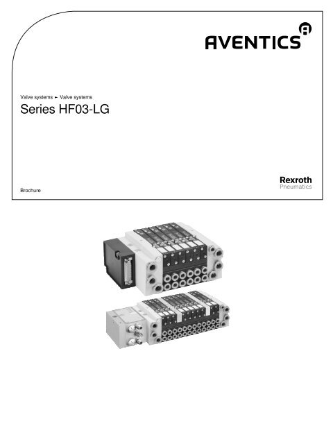
<strong>Series</strong> <strong>HF03</strong>-<strong>LG</strong><br />
Brochure
2<br />
Valve systems ► Valve systems<br />
<strong>Series</strong> <strong>HF03</strong>-<strong>LG</strong><br />
Valve system, configurable with push-in fitting Ø8 mm or 1/4” (inch) or thread connection G1/8 or 1/8 NPTF<br />
Valve system, <strong>Series</strong> <strong>HF03</strong>-<strong>LG</strong><br />
► Qn Max. = 700 l/min ► Multipole ► Electr. connection: D-Sub plug, 25-pin, on the side /<br />
D-Sub plug, 44-pin, on the side<br />
5<br />
Valve system, <strong>Series</strong> <strong>HF03</strong>-<strong>LG</strong><br />
► Qn Max. = 700 l/min ► Direct field bus connection (BDC) ► B-design 9<br />
Valve system, <strong>Series</strong> <strong>HF03</strong>-<strong>LG</strong><br />
► Qn Max. = 700 l/min ► Field bus connection with I/O functionality (CMS) ► B-design 12<br />
Valve system, <strong>Series</strong> <strong>HF03</strong>-<strong>LG</strong><br />
► Qn Max. = 700 l/min ► Connection with diagnosis (DDL) ► B-design 15<br />
Valve system, <strong>Series</strong> <strong>HF03</strong>-<strong>LG</strong><br />
► Qn Max. = 700 l/min ► Connection with diagnosis, optionally with I/O function (DDL)<br />
► B-design<br />
18<br />
Valve system, <strong>Series</strong> <strong>HF03</strong>-<strong>LG</strong><br />
► Qn Max. = 700 l/min ► Field bus connection with AS i ► B-design 21<br />
Valves<br />
2x3/2-directional valve, <strong>Series</strong> <strong>HF03</strong>-<strong>LG</strong><br />
► for <strong>Series</strong> <strong>HF03</strong>-<strong>LG</strong>, CL03, CL03-XL ► Qn = 850 l/min ► Pilot valve width: 16 mm<br />
► plate connection ► Manual override: with detent ► Pilot: External, internal<br />
26<br />
2x3/2-directional valve, <strong>Series</strong> <strong>HF03</strong>-<strong>LG</strong><br />
► for <strong>Series</strong> <strong>HF03</strong>-<strong>LG</strong>, CL03, CL03-XL ► Qn = 850 l/min ► Pilot valve width: 16 mm<br />
► plate connection ► Manual override: without detent ► Pilot: External, internal<br />
28<br />
5/2-directional valve, <strong>Series</strong> <strong>HF03</strong>-<strong>LG</strong><br />
► for <strong>Series</strong> <strong>HF03</strong>-<strong>LG</strong>, CL03, CL03-XL ► Qn = 850 l/min ► Pilot valve width: 16 mm<br />
► plate connection ► Manual override: with detent ► single solenoid, double solenoid<br />
► Pilot: External, internal<br />
30<br />
5/2-directional valve, <strong>Series</strong> <strong>HF03</strong>-<strong>LG</strong><br />
► for <strong>Series</strong> <strong>HF03</strong>-<strong>LG</strong>, CL03, CL03-XL ► Qn = 850 l/min ► Pilot valve width: 16 mm<br />
► plate connection ► Manual override: without detent ► single solenoid, double solenoid<br />
► Pilot: External, internal<br />
32<br />
5/3-directional valve, <strong>Series</strong> <strong>HF03</strong>-<strong>LG</strong><br />
► for <strong>Series</strong> <strong>HF03</strong>-<strong>LG</strong>, CL03, CL03-XL ► Qn = 850 l/min ► Pilot valve width: 16 mm<br />
► closed center ► plate connection ► Manual override: with detent ► Pilot: External,<br />
internal<br />
34<br />
5/3-directional valve, <strong>Series</strong> <strong>HF03</strong>-<strong>LG</strong><br />
► for <strong>Series</strong> <strong>HF03</strong>-<strong>LG</strong>, CL03, CL03-XL ► Qn = 850 l/min ► Pilot valve width: 16 mm<br />
► closed center ► plate connection ► Manual override: without detent ► Pilot: External,<br />
internal<br />
36<br />
Part numbers marked in bold are available from the central warehouse in Germany, see the shopping basket for more detailed information<br />
Pneumatics catalog, online PDF, as of 2015-10-21, ©AVENTICS S.à r.l., subject to change
3<br />
Valve systems ► Valve systems<br />
<strong>Series</strong> <strong>HF03</strong>-<strong>LG</strong><br />
Accessories<br />
Field Bus Modules<br />
Direct field bus connection (BDC)<br />
► Bus coupler with driver ► direct field bus connection ► Field bus protocol: PROFIBUS<br />
DP / CANopen / CANopen sb / DeviceNet / sercos III<br />
38<br />
Optional field bus connection with I/O function (CMS), B-design<br />
► Bus coupler with driver ► Field bus protocol: PROFIBUS DP / DeviceNet / CANopen /<br />
EtherNET/IP / PROFINET IO<br />
39<br />
Link structure DDL, B-design<br />
► B-design ► Driver 43<br />
Link structure DDL, B-design<br />
► Driver 45<br />
Fieldbus connection, <strong>Series</strong> AS-i<br />
► B-design ► Bus coupler with driver ► Field bus protocol: AS-i 47<br />
Fieldbus connection, <strong>Series</strong> AS-i<br />
► B-design ► Bus coupler with driver ► Field bus protocol: AS i with inputs 49<br />
ECV series for <strong>HF03</strong><br />
compact ejector, <strong>Series</strong> ECV<br />
► For <strong>HF03</strong> valve system 51<br />
Other accessories<br />
Pressure regulator subplate<br />
► Base plate connection, Base plate connection ► Poppet valve 57<br />
Pressure gauge<br />
► Front port ► Background color: Black ► Scale color: White ► Viewing window:<br />
Polystyrene ► Units: MPa<br />
58<br />
Part numbers marked in bold are available from the central warehouse in Germany, see the shopping basket for more detailed information<br />
Pneumatics catalog, online PDF, as of 2015-10-21, ©AVENTICS S.à r.l., subject to change
4<br />
Valve systems ► Valve systems<br />
<strong>Series</strong> <strong>HF03</strong>-<strong>LG</strong><br />
Exhaust module, for port channels 2, 4<br />
60<br />
Multipole plug D-Sub (25-pin)<br />
► Socket, D-Sub, 25-pin 61<br />
Multipole plug (44-pin)<br />
► high density ► Socket, D-Sub, 44-pin 63<br />
Multipole plug (44-pin)<br />
► Socket, D-Sub, 44-pin 65<br />
CKD kit, <strong>Series</strong> <strong>HF03</strong>-<strong>LG</strong><br />
► Metric version ► compressed air connection output: Ø 8 - G 1/8 ► Can be assembled<br />
into blocks ► Single base plate principle ► With collective pilot air exhaust<br />
67<br />
CKD kit, <strong>Series</strong> <strong>HF03</strong>-<strong>LG</strong><br />
► Inch version ► compressed air connection output: 1/8-27 NPTF - Ø 8 ► Can be<br />
assembled into blocks ► Single base plate principle ► With collective pilot air exhaust<br />
68<br />
<strong>Series</strong> QR1-S standard<br />
► Blanking plug ► pin bushing ► Ø 8 - Ø 12 ► QR1-S-RBS 70<br />
Blanking plate, <strong>Series</strong> <strong>HF03</strong>-<strong>LG</strong><br />
► for series <strong>HF03</strong>-<strong>LG</strong>, CL03-XL 71<br />
Accessories, <strong>Series</strong> <strong>HF03</strong>-<strong>LG</strong><br />
72<br />
Part numbers marked in bold are available from the central warehouse in Germany, see the shopping basket for more detailed information<br />
Pneumatics catalog, online PDF, as of 2015-10-21, ©AVENTICS S.à r.l., subject to change
Valve systems ► Valve systems<br />
Valve system, <strong>Series</strong> <strong>HF03</strong>-<strong>LG</strong><br />
► Qn Max. = 700 l/min ► Multipole ► Electr. connection: D-Sub plug, 25-pin, on the side / D-Sub plug, 44-pin, on<br />
the side<br />
5<br />
00125254<br />
Blocking principle<br />
Single base plate principle<br />
Working pressure min./max.<br />
2.5 bar / 10 bar<br />
Ambient temperature min./max.<br />
+0°C / +50°C<br />
Medium temperature min./max.<br />
+0°C / +50°C<br />
Medium<br />
Compressed air<br />
Max. particle size 5 µm<br />
Oil content of compressed air<br />
0 mg/m³<br />
Protection class<br />
IP65<br />
With connection<br />
Number of valve positions<br />
24 / 32<br />
Max.<br />
Number of solenoid coils<br />
24 / 32<br />
max.<br />
DC operating voltage<br />
24 V<br />
Voltage tolerance DC -15% / +20%<br />
An example configuration is illustrated. The delivered product may thus deviate from the illustration.<br />
Technical Remarks<br />
■ The min. control pressure must be adhered to, since otherwise faulty switching and valve failure may result!<br />
■ The pressure dew point must be at least 15 °C under ambient and medium temperature and may not exceed 3 °C.<br />
■ The oil content of compressed air must remain constant during the life cycle.<br />
■ Use only the approved oils from AVENTICS, see chapter „Technical information“.<br />
■ See the following pages on the series for technical data on individual components.<br />
■ The flow of the individual valves depends on the base plate, so here the flow is 700 l/min.<br />
■ For push-in fittings, only use plug accessories made of plastic (polyamide) from our catalog.<br />
■ It is necessary to maintain the electrical current in the coil of double solenoid valves to avoid unexpected auto-switching.<br />
Configurable product<br />
This product is configurable. Please use our Internet configurator at http://www.aventics.com or contact the<br />
nearest AVENTICS sales office.<br />
Part numbers marked in bold are available from the central warehouse in Germany, see the shopping basket for more detailed information<br />
Pneumatics catalog, online PDF, as of 2015-10-21, ©AVENTICS S.à r.l., subject to change
6<br />
Valve systems ► Valve systems<br />
Valve system, <strong>Series</strong> <strong>HF03</strong>-<strong>LG</strong><br />
► Qn Max. = 700 l/min ► Multipole ► Electr. connection: D-Sub plug, 25-pin, on the side / D-Sub plug, 44-pin, on<br />
the side<br />
Dimensions in mm<br />
1 = plug-in connection Ø 12 mm or 1/2”<br />
2 and 4 = plug-in connection Ø 8 mm or threaded connection G1/8 or 1/8 NPTF<br />
3 and 5 = plug-in connection Ø 12 mm or 1/2”<br />
R = collected pilot exhaust, plug-in connection Ø 8 mm or 1/4”<br />
X = external pilot control, plug-in connection Ø 8 mm or 1/4”, connection X plugged with internal pilot control<br />
An example configuration is illustrated. The delivered product may thus deviate from the illustration.<br />
00124858<br />
n 1 2 3 4 5 6 7 8 9 10 11 12 13 14<br />
A 82.8 98.6 114.4 130.2 146 161.8 177.6 193.4 209.2 225 240.8 256.6 272.4 288.2<br />
B 65.8 81.6 97.4 113.2 129 144.8 160.6 176.4 192.2 208 223.8 239.6 255.4 271.2<br />
n 15 16 17 18 19 20 21 22 23 24<br />
A 304 319.8 335.6 351.4 367.2 383 398.8 414.6 430.4 446.2<br />
B 287 302.8 318.6 334.4 350.2 366 381.8 397.6 413.4 429.2<br />
n = number of subbases<br />
Part numbers marked in bold are available from the central warehouse in Germany, see the shopping basket for more detailed information<br />
Pneumatics catalog, online PDF, as of 2015-10-21, ©AVENTICS S.à r.l., subject to change
1<br />
0<br />
1<br />
0<br />
1<br />
0<br />
1<br />
0<br />
1<br />
0<br />
1<br />
0<br />
1<br />
0<br />
1<br />
0<br />
1<br />
0<br />
1<br />
0<br />
1<br />
0<br />
1<br />
0<br />
1<br />
0<br />
1<br />
0<br />
1<br />
0<br />
1<br />
0<br />
1<br />
0<br />
5<br />
1<br />
3<br />
Valve systems ► Valve systems<br />
Valve system, <strong>Series</strong> <strong>HF03</strong>-<strong>LG</strong><br />
► Qn Max. = 700 l/min ► Multipole ► Electr. connection: D-Sub plug, 25-pin, on the side / D-Sub plug, 44-pin, on<br />
the side<br />
7<br />
Dimensions in inches<br />
5 ( 1/2") X ( 1/4")<br />
n<br />
R ( 1/4")<br />
3 ( 1/2")<br />
5 ( 1/2")<br />
3 ( 1/2")<br />
1.11<br />
0.48<br />
5<br />
3<br />
X<br />
1.32 2 ( 1/8 NPTF) 0.62<br />
1 ( 1/2")<br />
4 ( 1/8 NPTF)<br />
A<br />
1.32<br />
1.12<br />
B<br />
3.07<br />
0.33<br />
0.33<br />
2.64<br />
0.08<br />
12<br />
14<br />
12<br />
14<br />
14<br />
12<br />
14<br />
12<br />
14<br />
12<br />
14<br />
14<br />
12<br />
14<br />
12<br />
14<br />
14<br />
0.08<br />
5.70<br />
3.59<br />
1,97<br />
1.97<br />
1.19<br />
2.22<br />
3.07<br />
0.56<br />
0.51<br />
1 ( 1/2")<br />
0.26<br />
6,5<br />
1 = plug-in connection Ø 12 mm or 1/2”<br />
2 and 4 = plug-in connection Ø 8 mm or threaded connection G1/8 or 1/8 NPTF<br />
3 and 5 = plug-in connection Ø 12 mm or 1/2”<br />
R = collected pilot exhaust, plug-in connection Ø 8 mm or 1/4”<br />
X = external pilot control, plug-in connection Ø 8 mm or 1/4”, connection X plugged with internal pilot control<br />
An example configuration is illustrated. The delivered product may thus deviate from the illustration.<br />
00124858_a<br />
n 1 2 3 4 5 6 7 8 9 10 11 12 13 14<br />
A 3.26 3.88 4.5 5.13 5.75 6.37 6.99 7.61 8.24 8.86 9.48 10.1 10.72 11.35<br />
B 2.59 3.21 3.83 4.46 5.08 5.7 6.32 6.94 7.57 8.19 8.81 9.43 10.06 10.68<br />
n 15 16 17 18 19 20 21 22 23 24<br />
A 11.97 12.59 13.21 13.83 14.46 15.08 15.7 16.32 16.94 17.57<br />
B 11.3 11.92 12.54 13.17 13.79 14.41 15.03 15.65 16.28 16.9<br />
n = number of subbases<br />
Part numbers marked in bold are available from the central warehouse in Germany, see the shopping basket for more detailed information<br />
Pneumatics catalog, online PDF, as of 2015-10-21, ©AVENTICS S.à r.l., subject to change
8<br />
Valve systems ► Valve systems<br />
Valve system, <strong>Series</strong> <strong>HF03</strong>-<strong>LG</strong><br />
► Qn Max. = 700 l/min ► Multipole ► Electr. connection: D-Sub plug, 25-pin, on the side / D-Sub plug, 44-pin, on<br />
the side<br />
Multipole plug (25-pin), cable identification as per DIN 47100<br />
13<br />
1<br />
1<br />
13<br />
25<br />
14<br />
14<br />
25<br />
00136701<br />
00137724<br />
Socket (female)<br />
Plug (male)<br />
Pin 1 2 3 4 5 6 7 8 9 10 11 12 13<br />
Color white brown green yellow gray pink blue red black violet gray/pink red/blue white/<br />
green<br />
Pin 14 15 16 17 18 19 20 21 22 23 24 25<br />
Color brown/ white/ yellow/ white/gray gray/ white/pink pink/ white/blue brown/ white/red brown/red white/<br />
green yellow brown<br />
brown<br />
brown<br />
blue<br />
black<br />
Multipole plug (44-pin), cable identification as per DIN 47100<br />
15<br />
1<br />
1<br />
15<br />
15 14 13 12 11 10 9 8 7 6 5 4 3 2 1<br />
30 29 28 27 26 25 24 23 22 21 20 19 18 17 16<br />
44 43 42 41 40 39 38 37 36 35 34 33 32 31<br />
1 2 3 4 5 6 7 8 9 10 11 12 13 14 15<br />
16 17 18 19 20 21 22 23 24 25 26 27 28 29 30<br />
31 32 33 34 35 36 37 38 39 40 41 42 43 44<br />
44<br />
31<br />
31 44<br />
00137727<br />
00137727_a<br />
Socket (female)<br />
Plug (male)<br />
Pin 1 2 3 4 5 6 7 8 9 10 11 12 13<br />
Color white brown green yellow gray pink blue red black violet gray/pink red/blue white/<br />
green<br />
Pin 14 15 16 17 18 19 20 21 22 23 24 25<br />
Color brown/ white/ yellow/ white/gray gray/ white/pink pink/ white/blue brown/ white/red brown/red white/<br />
green yellow brown<br />
brown<br />
brown<br />
blue<br />
black<br />
Pin 26 27 28 29 30 31 32 33 34 35 36 37<br />
Color brown/ gray/ yellow/ pink/ yellow/ green/ yellow/ green/red yellow/red green/ yellow/ gray/blue<br />
black green gray green pink blue blue<br />
black black<br />
Pin 38 39 40 41 42 43 44<br />
Color pink/blue gray/red pink/red gray/black pink/black blue/black red/black<br />
Part numbers marked in bold are available from the central warehouse in Germany, see the shopping basket for more detailed information<br />
Pneumatics catalog, online PDF, as of 2015-10-21, ©AVENTICS S.à r.l., subject to change
Valve systems ► Valve systems<br />
Valve system, <strong>Series</strong> <strong>HF03</strong>-<strong>LG</strong><br />
► Qn Max. = 700 l/min ► Direct field bus connection (BDC) ► B-design<br />
9<br />
00130745<br />
Version<br />
Field bus<br />
Blocking principle<br />
Single base plate principle<br />
Working pressure min./max.<br />
2.5 bar / 10 bar<br />
Ambient temperature min./max.<br />
+0°C / +50°C<br />
Medium temperature min./max.<br />
+0°C / +50°C<br />
Medium<br />
Compressed air<br />
Max. particle size 5 µm<br />
Oil content of compressed air<br />
0 mg/m³<br />
Protection class, with plug<br />
IP65<br />
Number of valve positions 32<br />
Number of solenoid coils 32<br />
Operational voltage electronics<br />
24 V DC<br />
Electronics voltage tolerance -15% / +20%<br />
Lubricant<br />
ISO 21469 (NSF-H1)<br />
An example configuration is illustrated. The delivered product may thus deviate from the illustration.<br />
Technical Remarks<br />
■ The min. control pressure must be adhered to, since otherwise faulty switching and valve failure may result!<br />
■ The pressure dew point must be at least 15 °C under ambient and medium temperature and may not exceed 3 °C.<br />
■ The oil content of compressed air must remain constant during the life cycle.<br />
■ Use only the approved oils from AVENTICS, see chapter „Technical information“.<br />
■ See the following pages on the series for technical data on individual components.<br />
■ For technical data for electronics (link structures), see the Chapter “Field bus connections”.<br />
■ The flow of the individual valves depends on the base plate, so here the flow is 700 l/min.<br />
■ For push-in fittings, only use plug accessories made of plastic (polyamide) from our catalog.<br />
■ It is necessary to maintain the electrical current in the coil of double solenoid valves to avoid unexpected auto-switching.<br />
Configurable product<br />
This product is configurable. Please use our Internet configurator at http://www.aventics.com or contact the<br />
nearest AVENTICS sales office.<br />
Part numbers marked in bold are available from the central warehouse in Germany, see the shopping basket for more detailed information<br />
Pneumatics catalog, online PDF, as of 2015-10-21, ©AVENTICS S.à r.l., subject to change
7291<br />
Made in<br />
Germany<br />
1<br />
0<br />
1<br />
0<br />
1<br />
0<br />
1<br />
0<br />
1<br />
0<br />
5<br />
1<br />
3<br />
1<br />
0<br />
1<br />
0<br />
1<br />
0<br />
1<br />
0<br />
1<br />
0<br />
1<br />
0<br />
1<br />
0<br />
1<br />
0<br />
1<br />
0<br />
1<br />
0<br />
1<br />
0<br />
1<br />
0<br />
10<br />
Valve systems ► Valve systems<br />
Valve system, <strong>Series</strong> <strong>HF03</strong>-<strong>LG</strong><br />
► Qn Max. = 700 l/min ► Direct field bus connection (BDC) ► B-design<br />
Dimensions in mm<br />
5 ( 12) X ( 8)<br />
n<br />
R ( 8)<br />
3 ( 12)<br />
5 ( 12)<br />
3 ( 12)<br />
5<br />
X<br />
28,1<br />
12,1<br />
3<br />
13<br />
30,1<br />
56,5<br />
15,8<br />
4 ( 8)<br />
A<br />
33,5<br />
78<br />
73<br />
B<br />
67<br />
8,5<br />
8,5<br />
12<br />
14<br />
12<br />
14<br />
14<br />
12<br />
14<br />
12<br />
14<br />
12<br />
14<br />
14<br />
12<br />
14<br />
12<br />
14<br />
14<br />
50<br />
78<br />
2 ( 8)<br />
1 ( 12)<br />
1 ( 12)<br />
33<br />
6,5<br />
B<br />
135<br />
115<br />
A<br />
BDC-B-DP.32<br />
UL/DIA<br />
UQ1<br />
UQ2<br />
RUN/BF<br />
144,7<br />
BTN<br />
6,5<br />
1 = plug-in connection Ø 12 mm or plug-in connection 1/2”<br />
2 and 4 = plug-in connection Ø 8 mm or threaded connection G1/8 or 1/8 NPTF<br />
3 and 5 = plug-in connection Ø 12 mm or plug-in connection 1/2”<br />
R = collected pilot exhaust, plug-in connection Ø 8 mm or plug-in connection 1/4”<br />
X = external pilot control, plug-in connection Ø 8 mm or plug-in connection 1/4”, connection X plugged with internal pilot control<br />
An example configuration is illustrated. The delivered product may thus deviate from the illustration.<br />
00128617<br />
n 1 2 3 4 5 6 7 8 9 10 11 12 13 14<br />
A 82.8 98.6 114.4 130.2 146 161.8 177.6 193.4 209.2 225 240.8 256.6 272.4 288.2<br />
B 65.8 81.6 97.4 113.2 129 144.8 160.6 176.4 192.2 208 223.8 239.6 255.4 271.2<br />
n 15 16 17 18 19 20 21 22 23 24 25 26 27 28<br />
A 304 319.8 335.6 351.4 367.2 383 398.8 414.6 430.4 446.2 462 477.8 493.6 509.4<br />
B 287 302.8 318.6 334.4 350.2 366 381.8 397.6 413.4 429.2 445 460.8 476.6 492.4<br />
n 29 30 31 32<br />
A 525.2 541 556.8 572.6<br />
B 508.2 524 539.8 555.6<br />
n = number of subbases<br />
Part numbers marked in bold are available from the central warehouse in Germany, see the shopping basket for more detailed information<br />
Pneumatics catalog, online PDF, as of 2015-10-21, ©AVENTICS S.à r.l., subject to change
7291<br />
1<br />
0<br />
1<br />
0<br />
1<br />
0<br />
1<br />
0<br />
1<br />
0<br />
5<br />
1<br />
3<br />
1<br />
0<br />
1<br />
0<br />
1<br />
0<br />
1<br />
0<br />
1<br />
0<br />
1<br />
0<br />
1<br />
0<br />
1<br />
0<br />
1<br />
0<br />
1<br />
0<br />
1<br />
0<br />
1<br />
0<br />
Valve systems ► Valve systems<br />
Valve system, <strong>Series</strong> <strong>HF03</strong>-<strong>LG</strong><br />
► Qn Max. = 700 l/min ► Direct field bus connection (BDC) ► B-design<br />
11<br />
Dimensions in inches<br />
5 ( 1/2")<br />
3 ( 1/2")<br />
X ( 1/4")<br />
n<br />
R ( 1/4")<br />
5 ( 1/2")<br />
3 ( 1/2")<br />
1.11<br />
0.48<br />
5<br />
3<br />
X<br />
1.19<br />
1.32<br />
3.07<br />
2.87<br />
B<br />
2.64<br />
0.33<br />
0.33<br />
12<br />
14<br />
12<br />
14<br />
14<br />
12<br />
14<br />
12<br />
14<br />
12<br />
14<br />
14<br />
12<br />
14<br />
12<br />
14<br />
14<br />
1.97<br />
2.22<br />
3.07<br />
2 ( 1/8 NPTF) 0.62<br />
1 ( 1/2") 4 ( 1/8 NPTF)<br />
A<br />
0.51<br />
1 ( 1/2")<br />
1.30<br />
0.26<br />
B<br />
5.31<br />
4.53<br />
A<br />
BDC-B-DP.32<br />
UL/DIA<br />
UQ1<br />
UQ2<br />
RUN/BF<br />
5.70<br />
BTN<br />
Made in<br />
Germany<br />
0.26<br />
1 = plug-in connection Ø 12 mm or plug-in connection 1/2”<br />
2 and 4 = plug-in connection Ø 8 mm or threaded connection G1/8 or 1/8 NPTF<br />
3 and 5 = plug-in connection Ø 12 mm or plug-in connection 1/2”<br />
R = collected pilot exhaust, plug-in connection Ø 8 mm or plug-in connection 1/4”<br />
X = external pilot control, plug-in connection Ø 8 mm or plug-in connection 1/4”, connection X plugged with internal pilot control<br />
An example configuration is illustrated. The delivered product may thus deviate from the illustration.<br />
00128617_a<br />
n 1 2 3 4 5 6 7 8 9 10 11 12 13 14<br />
A 3.26 3.88 4.5 5.13 5.75 6.37 6.99 7.61 8.24 8.86 9.48 10.1 10.72 11.35<br />
B 2.59 3.21 3.83 4.46 5.08 5.7 6.32 6.94 7.57 8.19 8.81 9.43 10.06 10.68<br />
n 15 16 17 18 19 20 21 22 23 24 25 26 27 28<br />
A 11.97 12.59 13.21 13.83 14.46 15.08 15.7 16.32 16.94 17.57 18.19 18.81 19.43 20.06<br />
B 11.3 11.92 12.54 13.17 13.79 14.41 15.03 15.65 16.28 16.9 17.52 18.14 18.76 19.39<br />
n 29 30 31 32<br />
A 20.68 21.3 21.92 22.54<br />
B 20.01 20.63 21.25 21.87<br />
n = number of subbases<br />
Part numbers marked in bold are available from the central warehouse in Germany, see the shopping basket for more detailed information<br />
Pneumatics catalog, online PDF, as of 2015-10-21, ©AVENTICS S.à r.l., subject to change
12<br />
Valve systems ► Valve systems<br />
Valve system, <strong>Series</strong> <strong>HF03</strong>-<strong>LG</strong><br />
► Qn Max. = 700 l/min ► Field bus connection with I/O functionality (CMS) ► B-design<br />
00125893<br />
Version<br />
field bus CMS<br />
Blocking principle<br />
Single base plate principle<br />
Working pressure min./max.<br />
2.5 bar / 10 bar<br />
Ambient temperature min./max.<br />
+0°C / +50°C<br />
Medium temperature min./max.<br />
+0°C / +50°C<br />
Medium<br />
Compressed air<br />
Max. particle size 5 µm<br />
Oil content of compressed air<br />
0 mg/m³<br />
Protection class, with plug<br />
IP65<br />
Number of valve positions 32<br />
Operational voltage electronics<br />
24 V DC<br />
Electronics voltage tolerance -15% / +20%<br />
Lubricant<br />
ISO 21469 (NSF-H1)<br />
An example configuration is illustrated. The delivered product may thus deviate from the illustration.<br />
Technical Remarks<br />
■ The min. control pressure must be adhered to, since otherwise faulty switching and valve failure may result!<br />
■ The pressure dew point must be at least 15 °C under ambient and medium temperature and may not exceed 3 °C.<br />
■ The oil content of compressed air must remain constant during the life cycle.<br />
■ Use only the approved oils from AVENTICS, see chapter „Technical information“.<br />
■ See the following pages on the series for technical data on individual components.<br />
■ For technical data for electronics (link structures), see the Chapter “Field bus connections”.<br />
■ The flow of the individual valves depends on the base plate, so here the flow is 700 l/min.<br />
■ For push-in fittings, only use plug accessories made of plastic (polyamide) from our catalog.<br />
■ It is necessary to maintain the electrical current in the coil of double solenoid valves to avoid unexpected auto-switching.<br />
Configurable product<br />
This product is configurable. Please use our Internet configurator at http://www.aventics.com or contact the<br />
nearest AVENTICS sales office.<br />
Part numbers marked in bold are available from the central warehouse in Germany, see the shopping basket for more detailed information<br />
Pneumatics catalog, online PDF, as of 2015-10-21, ©AVENTICS S.à r.l., subject to change
Made in Germany<br />
7291 Made in Germany<br />
7291<br />
1<br />
0<br />
1<br />
0<br />
1<br />
0<br />
1<br />
0<br />
1<br />
0<br />
1<br />
0<br />
1<br />
0<br />
1<br />
0<br />
1<br />
0<br />
1<br />
0<br />
1<br />
0<br />
1<br />
0<br />
1<br />
0<br />
1<br />
0<br />
1<br />
0<br />
1<br />
0<br />
1<br />
0<br />
Valve systems ► Valve systems<br />
Valve system, <strong>Series</strong> <strong>HF03</strong>-<strong>LG</strong><br />
► Qn Max. = 700 l/min ► Field bus connection with I/O functionality (CMS) ► B-design<br />
13<br />
Dimensions in mm<br />
X ( 8)<br />
5 ( 12)<br />
3 ( 12)<br />
n<br />
R ( 8)<br />
5 ( 12)<br />
3 ( 12)<br />
I0<br />
I4<br />
43,5<br />
29<br />
I1<br />
I2<br />
I3<br />
I5<br />
I6<br />
I7<br />
A<br />
B<br />
30,1<br />
56,5<br />
67<br />
14,5<br />
11,5<br />
15,8<br />
33,5<br />
60<br />
A<br />
60<br />
B<br />
8,5<br />
8,5<br />
8,5<br />
2<br />
2<br />
12<br />
14<br />
12<br />
14<br />
14<br />
12<br />
14<br />
12<br />
14<br />
12<br />
14<br />
14<br />
12<br />
14<br />
12<br />
14<br />
14<br />
UL/DIA<br />
UQ1<br />
UQ2<br />
BF<br />
8 DI RMV04-DP<br />
BTN<br />
I0<br />
I1<br />
I2<br />
I3<br />
I4<br />
I5<br />
I6<br />
I7<br />
0.26<br />
17,5<br />
21,75<br />
78<br />
67<br />
43,5<br />
18<br />
34<br />
27<br />
33,5<br />
2 ( 8)<br />
1 ( 12)<br />
15,8<br />
4 ( 8)<br />
1 ( 12)<br />
12<br />
16<br />
13<br />
50<br />
2<br />
6,5<br />
50<br />
115<br />
6,5<br />
144,7<br />
1 = plug-in connection Ø 12 mm or 1/2”<br />
2 and 4 = plug-in connection Ø 8 mm or threaded connection G1/8 or 1/8 NPTF<br />
3 and 5 = plug-in connection Ø 12 mm or 1/2”<br />
R = collected pilot exhaust, plug-in connection Ø 8 mm or 1/4”<br />
X = external pilot control, plug-in connection Ø 8 mm or 1/4”, connection X plugged with internal pilot control<br />
An example configuration is illustrated. The delivered product may thus deviate from the illustration.<br />
00124629<br />
n 1 2 3 4 5 6 7 8 9 10 11 12 13 14<br />
A 82.8 98.6 114.4 130.2 146 161.8 177.6 193.4 209.2 225 240.8 256.6 272.4 288.2<br />
B 65.8 81.6 97.4 113.2 129 144.8 160.6 176.4 192.2 208 223.8 239.6 255.4 271.2<br />
n 15 16 17 18 19 20 21 22 23 24 25 26 27 28<br />
A 304 319.8 335.6 351.4 367.2 383 398.8 414.6 430.4 446.2 462 477.8 493.6 509.4<br />
B 287 302.8 318.6 334.4 350.2 366 381.8 397.6 413.4 429.2 445 460.8 476.6 492.4<br />
n 29 30 31 32<br />
A 525.2 541 556.8 572.6<br />
B 508.2 524 539.8 555.6<br />
n = number of subbases<br />
Part numbers marked in bold are available from the central warehouse in Germany, see the shopping basket for more detailed information<br />
Pneumatics catalog, online PDF, as of 2015-10-21, ©AVENTICS S.à r.l., subject to change
Made in Germany<br />
7291 Made in Germany<br />
7291<br />
1<br />
0<br />
1<br />
0<br />
1<br />
0<br />
1<br />
0<br />
1<br />
0<br />
1<br />
0<br />
1<br />
0<br />
1<br />
0<br />
1<br />
0<br />
1<br />
0<br />
1<br />
0<br />
1<br />
0<br />
1<br />
0<br />
1<br />
0<br />
1<br />
0<br />
1<br />
0<br />
1<br />
0<br />
14<br />
Valve systems ► Valve systems<br />
Valve system, <strong>Series</strong> <strong>HF03</strong>-<strong>LG</strong><br />
► Qn Max. = 700 l/min ► Field bus connection with I/O functionality (CMS) ► B-design<br />
Dimensions in inches<br />
X ( 1/4")<br />
5 ( 1/2")<br />
3 ( 1/2")<br />
n<br />
R ( 1/4")<br />
5 ( 1/2")<br />
3 ( 1/2")<br />
I0<br />
I4<br />
1.71<br />
1.14<br />
I1<br />
I2<br />
I3<br />
I5<br />
I6<br />
I7<br />
A<br />
B<br />
1.19<br />
2.22<br />
1.32<br />
2.36<br />
A<br />
2.36<br />
B<br />
0.35<br />
0.33<br />
0.33<br />
0.08<br />
0.08<br />
UL/DIA<br />
UQ1<br />
UQ2<br />
BF<br />
14<br />
12<br />
14<br />
12<br />
14<br />
14<br />
12<br />
14<br />
12<br />
14<br />
12<br />
14<br />
14<br />
12<br />
14<br />
12<br />
14<br />
8 DI RMV04-DP<br />
BTN<br />
I0<br />
I1<br />
I2<br />
I3<br />
I4<br />
I5<br />
I6<br />
I7<br />
0.26<br />
0.46<br />
0.86<br />
3.07<br />
2.64<br />
1.71<br />
2.64<br />
0.57<br />
0.45<br />
1.34<br />
0.71<br />
1.06<br />
1.32<br />
0.62 0.62<br />
2 (1/8 NPTF)<br />
1 ( 1/2") 4 (1/8 NPTF)<br />
1 ( 1/2")<br />
0.48<br />
0.63<br />
0.51<br />
1.97<br />
0.08<br />
0.26<br />
1.97<br />
4.53<br />
0.26<br />
5.70<br />
1 = plug-in connection Ø 12 mm or 1/2”<br />
2 and 4 = plug-in connection Ø 8 mm or threaded connection G1/8 or 1/8 NPTF<br />
3 and 5 = plug-in connection Ø 12 mm or 1/2”<br />
R = collected pilot exhaust, plug-in connection Ø 8 mm or 1/4”<br />
X = external pilot control, plug-in connection Ø 8 mm or 1/4”, connection X plugged with internal pilot control<br />
An example configuration is illustrated. The delivered product may thus deviate from the illustration.<br />
00124629_a<br />
n 1 2 3 4 5 6 7 8 9 10 11 12 13 14<br />
A 3.26 3.88 4.5 5.13 5.75 6.37 6.99 7.61 8.24 8.86 9.48 10.1 10.72 11.35<br />
B 2.59 3.21 3.83 4.46 5.08 5.7 6.32 6.94 7.57 8.19 8.81 9.43 10.06 10.68<br />
n 15 16 17 18 19 20 21 22 23 24 25 26 27 28<br />
A 11.97 12.59 13.21 13.83 14.46 15.08 15.7 16.32 16.94 17.57 18.19 18.81 19.43 20.06<br />
B 11.3 11.92 12.54 13.17 13.79 14.41 15.03 15.65 16.28 16.9 17.52 18.14 18.76 19.39<br />
n 29 30 31 32<br />
A 20.68 21.3 21.92 22.54<br />
B 20.01 20.63 21.25 21.87<br />
n = number of subbases<br />
Part numbers marked in bold are available from the central warehouse in Germany, see the shopping basket for more detailed information<br />
Pneumatics catalog, online PDF, as of 2015-10-21, ©AVENTICS S.à r.l., subject to change
Valve systems ► Valve systems<br />
Valve system, <strong>Series</strong> <strong>HF03</strong>-<strong>LG</strong><br />
► Qn Max. = 700 l/min ► Connection with diagnosis (DDL) ► B-design<br />
15<br />
00130745<br />
Version<br />
Link structure DDL<br />
Blocking principle<br />
Single base plate principle<br />
Working pressure min./max.<br />
2.5 bar / 10 bar<br />
Ambient temperature min./max.<br />
+0°C / +50°C<br />
Medium temperature min./max.<br />
+0°C / +50°C<br />
Medium<br />
Compressed air<br />
Max. particle size 5 µm<br />
Oil content of compressed air<br />
0 mg/m³<br />
Protection class, with plug<br />
IP65<br />
Number of valve positions 32<br />
Number of solenoid coils 32<br />
Operational voltage electronics<br />
24 V DC<br />
Electronics voltage tolerance -15% / +20%<br />
Lubricant<br />
ISO 21469 (NSF-H1)<br />
An example configuration is illustrated. The delivered product may thus deviate from the illustration.<br />
Technical Remarks<br />
■ The min. control pressure must be adhered to, since otherwise faulty switching and valve failure may result!<br />
■ The pressure dew point must be at least 15 °C under ambient and medium temperature and may not exceed 3 °C.<br />
■ The oil content of compressed air must remain constant during the life cycle.<br />
■ Use only the approved oils from AVENTICS, see chapter „Technical information“.<br />
■ See the following pages on the series for technical data on individual components.<br />
■ For technical data for electronics (link structures), see the Chapter “Field bus connections”.<br />
■ The flow of the individual valves depends on the base plate, so here the flow is 700 l/min.<br />
■ For push-in fittings, only use plug accessories made of plastic (polyamide) from our catalog.<br />
■ It is necessary to maintain the electrical current in the coil of double solenoid valves to avoid unexpected auto-switching.<br />
Configurable product<br />
This product is configurable. Please use our Internet configurator at http://www.aventics.com or contact the<br />
nearest AVENTICS sales office.<br />
Part numbers marked in bold are available from the central warehouse in Germany, see the shopping basket for more detailed information<br />
Pneumatics catalog, online PDF, as of 2015-10-21, ©AVENTICS S.à r.l., subject to change
7291<br />
Made in<br />
Germany<br />
1<br />
0<br />
1<br />
0<br />
1<br />
0<br />
1<br />
0<br />
1<br />
0<br />
5<br />
1<br />
3<br />
1<br />
0<br />
1<br />
0<br />
1<br />
0<br />
1<br />
0<br />
1<br />
0<br />
1<br />
0<br />
1<br />
0<br />
1<br />
0<br />
1<br />
0<br />
1<br />
0<br />
1<br />
0<br />
1<br />
0<br />
16<br />
Valve systems ► Valve systems<br />
Valve system, <strong>Series</strong> <strong>HF03</strong>-<strong>LG</strong><br />
► Qn Max. = 700 l/min ► Connection with diagnosis (DDL) ► B-design<br />
Dimensions in mm<br />
5 ( 12) X ( 8)<br />
n<br />
R ( 8)<br />
3 ( 12)<br />
5 ( 12)<br />
3 ( 12)<br />
5<br />
X<br />
28,1<br />
12,1<br />
3<br />
13<br />
30,1<br />
56,5<br />
15,8<br />
4 ( 8)<br />
A<br />
33,5<br />
78<br />
73<br />
B<br />
67<br />
8,5<br />
8,5<br />
12<br />
14<br />
12<br />
14<br />
14<br />
12<br />
14<br />
12<br />
14<br />
12<br />
14<br />
14<br />
12<br />
14<br />
12<br />
14<br />
14<br />
50<br />
78<br />
2 ( 8)<br />
1 ( 12)<br />
1 ( 12)<br />
33<br />
6,5<br />
B<br />
135<br />
115<br />
A<br />
BDC-B-DP.32<br />
DDL<br />
SENSOR<br />
Ubyte 1<br />
Ubyte 2<br />
Ubyte 3<br />
Ubyte 4<br />
DDL<br />
BTN<br />
144,7<br />
6,5<br />
1 = plug-in connection Ø 12 mm or plug-in connection 1/2”<br />
2 and 4 = plug-in connection Ø 8 mm or threaded connection G1/8 or 1/8 NPTF<br />
3 and 5 = plug-in connection Ø 12 mm or plug-in connection 1/2”<br />
R = collected pilot exhaust, plug-in connection Ø 8 mm or plug-in connection 1/4”<br />
X = external pilot control, plug-in connection Ø 8 mm or plug-in connection 1/4”, connection X plugged with internal pilot control<br />
An example configuration is illustrated. The delivered product may thus deviate from the illustration.<br />
00128618<br />
n 1 2 3 4 5 6 7 8 9 10 11 12 13 14<br />
A 82.8 98.6 114.4 130.2 146 161.8 177.6 193.4 209.2 225 240.8 256.6 272.4 288.2<br />
B 65.8 81.6 97.4 113.2 129 144.8 160.6 176.4 192.2 208 223.8 239.6 255.4 271.2<br />
n 15 16 17 18 19 20 21 22 23 24 25 26 27 28<br />
A 304 319.8 335.6 351.4 367.2 383 398.8 414.6 430.4 446.2 462 477.8 493.6 509.4<br />
B 287 302.8 318.6 334.4 350.2 366 381.8 397.6 413.4 429.2 445 460.8 476.6 492.4<br />
n 29 30 31 32<br />
A 525.2 541 556.8 572.6<br />
B 508.2 524 539.8 555.6<br />
n = number of subbases<br />
Part numbers marked in bold are available from the central warehouse in Germany, see the shopping basket for more detailed information<br />
Pneumatics catalog, online PDF, as of 2015-10-21, ©AVENTICS S.à r.l., subject to change
7291<br />
1<br />
0<br />
1<br />
0<br />
1<br />
0<br />
1<br />
0<br />
1<br />
0<br />
5<br />
1<br />
3<br />
1<br />
0<br />
1<br />
0<br />
1<br />
0<br />
1<br />
0<br />
1<br />
0<br />
1<br />
0<br />
1<br />
0<br />
1<br />
0<br />
1<br />
0<br />
1<br />
0<br />
1<br />
0<br />
1<br />
0<br />
Valve systems ► Valve systems<br />
Valve system, <strong>Series</strong> <strong>HF03</strong>-<strong>LG</strong><br />
► Qn Max. = 700 l/min ► Connection with diagnosis (DDL) ► B-design<br />
17<br />
Dimensions in inches<br />
5 ( 1/2")<br />
3 ( 1/2")<br />
X ( 1/4")<br />
n<br />
R ( 1/4")<br />
5 ( 1/2")<br />
3 ( 1/2")<br />
1.11<br />
0.48<br />
5<br />
3<br />
X<br />
1.19<br />
2.22<br />
3.07<br />
1.32<br />
3.07<br />
2.87<br />
B<br />
2.64<br />
0.33<br />
0.33<br />
12<br />
14<br />
12<br />
14<br />
14<br />
12<br />
14<br />
12<br />
14<br />
12<br />
14<br />
14<br />
12<br />
14<br />
12<br />
14<br />
14<br />
1.97<br />
2 ( 1/8 NPTF) 0.62<br />
1 ( 1/2") 4 ( 1/8 NPTF)<br />
A<br />
0.51<br />
1 ( 1/2")<br />
1.30<br />
0.26<br />
B<br />
5.31<br />
4.53<br />
A<br />
BDC-B-DP.32<br />
DDL<br />
BTN<br />
SENSOR<br />
Ubyte 1<br />
Ubyte 2<br />
Ubyte 3<br />
Ubyte 4<br />
DDL<br />
Made in<br />
Germany<br />
5.70<br />
0.26<br />
1 = plug-in connection Ø 12 mm or plug-in connection 1/2”<br />
2 and 4 = plug-in connection Ø 8 mm or threaded connection G1/8 or 1/8 NPTF<br />
3 and 5 = plug-in connection Ø 12 mm or plug-in connection 1/2”<br />
R = collected pilot exhaust, plug-in connection Ø 8 mm or plug-in connection 1/4”<br />
X = external pilot control, plug-in connection Ø 8 mm or plug-in connection 1/4”, connection X plugged with internal pilot control<br />
An example configuration is illustrated. The delivered product may thus deviate from the illustration.<br />
00128618_a<br />
n 1 2 3 4 5 6 7 8 9 10 11 12 13 14<br />
A 3.26 3.88 4.5 5.13 5.75 6.37 6.99 7.61 8.24 8.86 9.48 10.1 10.72 11.35<br />
B 2.59 3.21 3.83 4.46 5.08 5.7 6.32 6.94 7.57 8.19 8.81 9.43 10.06 10.68<br />
n 15 16 17 18 19 20 21 22 23 24 25 26 27 28<br />
A 11.97 12.59 13.21 13.83 14.46 15.08 15.7 16.32 16.94 17.57 18.19 18.81 19.43 20.06<br />
B 11.3 11.92 12.54 13.17 13.79 14.41 15.03 15.65 16.28 16.9 17.52 18.14 18.76 19.39<br />
n 29 30 31 32<br />
A 20.68 21.3 21.92 22.54<br />
B 20.01 20.63 21.25 21.87<br />
n = number of subbases<br />
Part numbers marked in bold are available from the central warehouse in Germany, see the shopping basket for more detailed information<br />
Pneumatics catalog, online PDF, as of 2015-10-21, ©AVENTICS S.à r.l., subject to change
18<br />
Valve systems ► Valve systems<br />
Valve system, <strong>Series</strong> <strong>HF03</strong>-<strong>LG</strong><br />
► Qn Max. = 700 l/min ► Connection with diagnosis, optionally with I/O function (DDL) ► B-design<br />
00125893<br />
Version<br />
Link structure DDL<br />
Blocking principle<br />
Single base plate principle<br />
Working pressure min./max.<br />
2.5 bar / 10 bar<br />
Ambient temperature min./max.<br />
+0°C / +50°C<br />
Medium temperature min./max.<br />
+0°C / +50°C<br />
Medium<br />
Compressed air<br />
Max. particle size 5 µm<br />
Oil content of compressed air<br />
0 mg/m³<br />
Protection class, with plug<br />
IP65<br />
Number of valve positions 24<br />
Operational voltage electronics<br />
24 V DC<br />
Electronics voltage tolerance -15% / +20%<br />
Lubricant<br />
ISO 21469 (NSF-H1)<br />
An example configuration is illustrated. The delivered product may thus deviate from the illustration.<br />
Technical Remarks<br />
■ The min. control pressure must be adhered to, since otherwise faulty switching and valve failure may result!<br />
■ The pressure dew point must be at least 15 °C under ambient and medium temperature and may not exceed 3 °C.<br />
■ The oil content of compressed air must remain constant during the life cycle.<br />
■ Use only the approved oils from AVENTICS, see chapter „Technical information“.<br />
■ See the following pages on the series for technical data on individual components.<br />
■ For technical data for electronics (link structures), see the Chapter “Field bus connections”.<br />
■ The flow of the individual valves depends on the base plate, so here the flow is 700 l/min.<br />
■ For push-in fittings, only use plug accessories made of plastic (polyamide) from our catalog.<br />
■ It is necessary to maintain the electrical current in the coil of double solenoid valves to avoid unexpected auto-switching.<br />
Configurable product<br />
This product is configurable. Please use our Internet configurator at http://www.aventics.com or contact the<br />
nearest AVENTICS sales office.<br />
Part numbers marked in bold are available from the central warehouse in Germany, see the shopping basket for more detailed information<br />
Pneumatics catalog, online PDF, as of 2015-10-21, ©AVENTICS S.à r.l., subject to change
Made in Germany<br />
7291 Made in Germany<br />
7291<br />
1<br />
0<br />
1<br />
0<br />
1<br />
0<br />
1<br />
0<br />
1<br />
0<br />
1<br />
0<br />
1<br />
0<br />
1<br />
0<br />
1<br />
0<br />
1<br />
0<br />
1<br />
0<br />
1<br />
0<br />
1<br />
0<br />
1<br />
0<br />
1<br />
0<br />
1<br />
0<br />
1<br />
0<br />
Valve systems ► Valve systems<br />
Valve system, <strong>Series</strong> <strong>HF03</strong>-<strong>LG</strong><br />
► Qn Max. = 700 l/min ► Connection with diagnosis, optionally with I/O function (DDL) ► B-design<br />
19<br />
Dimensions in mm<br />
X ( 8)<br />
5 ( 12)<br />
3 ( 12)<br />
n<br />
R ( 8)<br />
5 ( 12)<br />
3 ( 12)<br />
I0<br />
I4<br />
43,5<br />
29<br />
I1<br />
I2<br />
I3<br />
I5<br />
I6<br />
I7<br />
A<br />
B<br />
30,1<br />
56,5<br />
67<br />
14,5<br />
11,5<br />
18<br />
34<br />
15,8<br />
33,5<br />
60<br />
A<br />
60<br />
B<br />
8,5<br />
8,5<br />
8,5<br />
2<br />
2<br />
12<br />
14<br />
12<br />
14<br />
14<br />
12<br />
14<br />
12<br />
14<br />
12<br />
14<br />
14<br />
12<br />
14<br />
12<br />
14<br />
14<br />
UL/DIA<br />
UQ1<br />
UQ2<br />
BF<br />
8 DI RMV04-DP<br />
BTN<br />
I0<br />
I1<br />
I2<br />
I3<br />
I4<br />
I5<br />
I6<br />
I7<br />
0.26<br />
17,5<br />
21,75<br />
78<br />
67<br />
43,5<br />
27<br />
33,5<br />
2 ( 8)<br />
1 ( 12)<br />
15,8<br />
4 ( 8)<br />
1 ( 12)<br />
12<br />
16<br />
13<br />
50<br />
2<br />
6,5<br />
50<br />
115<br />
6,5<br />
144,7<br />
1 = plug-in connection Ø 12 mm or 1/2”<br />
2 and 4 = plug-in connection Ø 8 mm or threaded connection G1/8 or 1/8 NPTF<br />
3 and 5 = plug-in connection Ø 12 mm or 1/2”<br />
R = collected pilot exhaust, plug-in connection Ø 8 mm or 1/4”<br />
X = external pilot control, plug-in connection Ø 8 mm or 1/4”, connection X plugged with internal pilot control<br />
An example configuration is illustrated. The delivered product may thus deviate from the illustration.<br />
00124629<br />
n 1 2 3 4 5 6 7 8 9 10 11 12 13 14<br />
A 82.8 98.6 114.4 130.2 146 161.8 177.6 193.4 209.2 225 240.8 256.6 272.4 288.2<br />
B 65.8 81.6 97.4 113.2 129 144.8 160.6 176.4 192.2 208 223.8 239.6 255.4 271.2<br />
n 15 16 17 18 19 20 21 22 23 24<br />
A 304 319.8 335.6 351.4 367.2 383 398.8 414.6 430.4 446.2<br />
B 287 302.8 318.6 334.4 350.2 366 381.8 397.6 413.4 429.2<br />
n = number of subbases<br />
Part numbers marked in bold are available from the central warehouse in Germany, see the shopping basket for more detailed information<br />
Pneumatics catalog, online PDF, as of 2015-10-21, ©AVENTICS S.à r.l., subject to change
Made in Germany<br />
7291 Made in Germany<br />
7291<br />
1<br />
0<br />
1<br />
0<br />
1<br />
0<br />
1<br />
0<br />
1<br />
0<br />
1<br />
0<br />
1<br />
0<br />
1<br />
0<br />
1<br />
0<br />
1<br />
0<br />
1<br />
0<br />
1<br />
0<br />
1<br />
0<br />
1<br />
0<br />
1<br />
0<br />
1<br />
0<br />
1<br />
0<br />
20<br />
Valve systems ► Valve systems<br />
Valve system, <strong>Series</strong> <strong>HF03</strong>-<strong>LG</strong><br />
► Qn Max. = 700 l/min ► Connection with diagnosis, optionally with I/O function (DDL) ► B-design<br />
Dimensions in inches<br />
X ( 1/4")<br />
5 ( 1/2")<br />
3 ( 1/2")<br />
n<br />
R ( 1/4")<br />
5 ( 1/2")<br />
3 ( 1/2")<br />
I0<br />
I4<br />
1.71<br />
1.14<br />
I1<br />
I2<br />
I3<br />
I5<br />
I6<br />
I7<br />
A<br />
B<br />
1.19<br />
2.22<br />
2.64<br />
0.57<br />
0.45<br />
1.32<br />
2.36<br />
A<br />
2.36<br />
B<br />
0.35<br />
0.33<br />
0.33<br />
0.08<br />
0.08<br />
UL/DIA<br />
UQ1<br />
UQ2<br />
BF<br />
14<br />
12<br />
14<br />
12<br />
14<br />
14<br />
12<br />
14<br />
12<br />
14<br />
12<br />
14<br />
14<br />
12<br />
14<br />
12<br />
14<br />
8 DI RMV04-DP<br />
BTN<br />
I0<br />
I1<br />
I2<br />
I3<br />
I4<br />
I5<br />
I6<br />
I7<br />
0.26<br />
0.46<br />
0.86<br />
3.07<br />
2.64<br />
1.71<br />
1.34<br />
0.71<br />
1.06<br />
1.32<br />
0.62 0.62<br />
2 (1/8 NPTF)<br />
1 ( 1/2") 4 (1/8 NPTF)<br />
1 ( 1/2")<br />
0.48<br />
0.63<br />
0.51<br />
1.97<br />
0.08<br />
0.26<br />
1.97<br />
4.53<br />
0.26<br />
5.70<br />
1 = plug-in connection Ø 12 mm or 1/2”<br />
2 and 4 = plug-in connection Ø 8 mm or threaded connection G1/8 or 1/8 NPTF<br />
3 and 5 = plug-in connection Ø 12 mm or 1/2”<br />
R = collected pilot exhaust, plug-in connection Ø 8 mm or 1/4”<br />
X = external pilot control, plug-in connection Ø 8 mm or 1/4”, connection X plugged with internal pilot control<br />
An example configuration is illustrated. The delivered product may thus deviate from the illustration.<br />
00124629_a<br />
n 1 2 3 4 5 6 7 8 9 10 11 12 13 14<br />
A 3.26 3.88 4.5 5.13 5.75 6.37 6.99 7.61 8.24 8.86 9.48 10.1 10.72 11.35<br />
B 2.59 3.21 3.83 4.46 5.08 5.7 6.32 6.94 7.57 8.19 8.81 9.43 10.06 10.68<br />
n 15 16 17 18 19 20 21 22 23 24<br />
A 11.97 12.59 13.21 13.83 14.46 15.08 15.7 16.32 16.94 17.57<br />
B 11.3 11.92 12.54 13.17 13.79 14.41 15.03 15.65 16.28 16.9<br />
n = number of subbases<br />
Part numbers marked in bold are available from the central warehouse in Germany, see the shopping basket for more detailed information<br />
Pneumatics catalog, online PDF, as of 2015-10-21, ©AVENTICS S.à r.l., subject to change
Valve systems ► Valve systems<br />
Valve system, <strong>Series</strong> <strong>HF03</strong>-<strong>LG</strong><br />
► Qn Max. = 700 l/min ► Field bus connection with AS i ► B-design<br />
21<br />
00125158<br />
Version<br />
Field bus<br />
Blocking principle<br />
Single base plate principle<br />
Working pressure min./max.<br />
2.5 bar / 10 bar<br />
Ambient temperature min./max.<br />
+0°C / +50°C<br />
Medium temperature min./max.<br />
+0°C / +50°C<br />
Medium<br />
Compressed air<br />
Max. particle size 5 µm<br />
Oil content of compressed air<br />
0 mg/m³<br />
Protection class, with plug<br />
IP65<br />
Number of valve positions 8<br />
Operational voltage electronics<br />
24 V DC<br />
Electronics voltage tolerance -15% / +20%<br />
Power supply connection<br />
Black AS-i flat cable<br />
Communication port<br />
Yellow AS-i flat cable<br />
Lubricant<br />
ISO 21469 (NSF-H1)<br />
An example configuration is illustrated. The delivered product may thus deviate from the illustration.<br />
Technical Remarks<br />
■ The min. control pressure must be adhered to, since otherwise faulty switching and valve failure may result!<br />
■ The pressure dew point must be at least 15 °C under ambient and medium temperature and may not exceed 3 °C.<br />
■ The oil content of compressed air must remain constant during the life cycle.<br />
■ Use only the approved oils from AVENTICS, see chapter „Technical information“.<br />
■ See the following pages on the series for technical data on individual components.<br />
■ For technical data for electronics (link structures), see the Chapter “Field bus connections”.<br />
■ The flow of the individual valves depends on the base plate, so here the flow is 700 l/min.<br />
■ For push-in fittings, only use plug accessories made of plastic (polyamide) from our catalog.<br />
■ It is necessary to maintain the electrical current in the coil of double solenoid valves to avoid unexpected auto-switching.<br />
Configurable product<br />
This product is configurable. Please use our Internet configurator at http://www.aventics.com or contact the<br />
nearest AVENTICS sales office.<br />
Part numbers marked in bold are available from the central warehouse in Germany, see the shopping basket for more detailed information<br />
Pneumatics catalog, online PDF, as of 2015-10-21, ©AVENTICS S.à r.l., subject to change
Made in Germany 7291<br />
1<br />
0<br />
1<br />
0<br />
1<br />
0<br />
1<br />
0<br />
1<br />
0<br />
5<br />
1<br />
3<br />
1<br />
0<br />
1<br />
0<br />
1<br />
0<br />
1<br />
0<br />
1<br />
0<br />
1<br />
0<br />
1<br />
0<br />
1<br />
0<br />
1<br />
0<br />
1<br />
0<br />
1<br />
0<br />
1<br />
0<br />
22<br />
Valve systems ► Valve systems<br />
Valve system, <strong>Series</strong> <strong>HF03</strong>-<strong>LG</strong><br />
► Qn Max. = 700 l/min ► Field bus connection with AS i ► B-design<br />
Dimensions in mm, 8DI/8DO-AUX, 4DI/4DO-AUX<br />
X ( 1/4")<br />
5 ( 1/2")<br />
3 ( 1/2")<br />
n<br />
R ( 1/4")<br />
5 ( 1/2")<br />
3 ( 1/2")<br />
4.53 1.71<br />
1.14<br />
1.97<br />
0.26<br />
0.57<br />
0.45<br />
0.71<br />
0.35<br />
0.08<br />
I0 I4<br />
AUX<br />
PWR<br />
I1 I5<br />
FAULT1<br />
FAULT2<br />
I2 I6<br />
I3 I7<br />
1.06<br />
0.94<br />
2.36<br />
0.38<br />
PWR<br />
S1<br />
ASI-8DI/8DO_AUX<br />
BTN1<br />
BTN2<br />
AUX<br />
5<br />
3<br />
X<br />
1.32<br />
0.62 0.62<br />
2 (1/8 NPTF)<br />
1 ( 1/2") 4 (1/8 NPTF)<br />
0.33<br />
14<br />
12<br />
14<br />
12<br />
14<br />
14<br />
A<br />
B<br />
12<br />
14<br />
12<br />
14<br />
12<br />
14<br />
14<br />
1 ( 1/2")<br />
12<br />
14<br />
12<br />
14<br />
0.33<br />
0.08<br />
1.32<br />
0.48<br />
0.63<br />
0.51<br />
0.26<br />
1.97<br />
5.70<br />
1.19<br />
2.22<br />
2.64<br />
3.07<br />
2.64<br />
0.26<br />
1 = plug-in connection Ø 12 mm or 1/2”<br />
2 and 4 = plug-in connection Ø 8 mm or threaded connection G1/8 or 1/8 NPTF<br />
3 and 5 = plug-in connection Ø 12 mm or 1/2”<br />
R = collected pilot exhaust, plug-in connection Ø 8 mm or 1/4”<br />
X = external pilot control, plug-in connection Ø 8 mm or 1/4”, connection X plugged with internal pilot control<br />
An example configuration is illustrated. The delivered product may thus deviate from the illustration.<br />
00124630<br />
n 1 2 3 4 5 6 7 8<br />
A 82.8 98.6 114.4 130.2 146 161.8 177.6 193.4<br />
B 65.8 81.6 97.4 113.2 129 144.8 160.6 176.4<br />
n = number of subbases<br />
Part numbers marked in bold are available from the central warehouse in Germany, see the shopping basket for more detailed information<br />
Pneumatics catalog, online PDF, as of 2015-10-21, ©AVENTICS S.à r.l., subject to change
Valve systems ► Valve systems<br />
Valve system, <strong>Series</strong> <strong>HF03</strong>-<strong>LG</strong><br />
► Qn Max. = 700 l/min ► Field bus connection with AS i ► B-design<br />
23<br />
Dimensions in mm, 8DO-AUX, 4DO-AUX<br />
1 = plug-in connection Ø 12 mm or 1/2”<br />
2 and 4 = plug-in connection Ø 8 mm or threaded connection G1/8 or 1/8 NPTF<br />
3 and 5 = plug-in connection Ø 12 mm or 1/2”<br />
R = collected pilot exhaust, plug-in connection Ø 8 mm or 1/4”<br />
X = external pilot control, plug-in connection Ø 8 mm or 1/4”, connection X plugged with internal pilot control<br />
An example configuration is illustrated. The delivered product may thus deviate from the illustration.<br />
00124631<br />
n 1 2 3 4<br />
A 82.8 98.6 114.4 130.2<br />
B 65.8 81.6 97.4 113.2<br />
n = number of subbases<br />
Part numbers marked in bold are available from the central warehouse in Germany, see the shopping basket for more detailed information<br />
Pneumatics catalog, online PDF, as of 2015-10-21, ©AVENTICS S.à r.l., subject to change
Made in Germany 7291<br />
1<br />
0<br />
1<br />
0<br />
1<br />
0<br />
1<br />
0<br />
1<br />
0<br />
5<br />
1<br />
3<br />
1<br />
0<br />
1<br />
0<br />
1<br />
0<br />
1<br />
0<br />
1<br />
0<br />
1<br />
0<br />
1<br />
0<br />
1<br />
0<br />
1<br />
0<br />
1<br />
0<br />
1<br />
0<br />
1<br />
0<br />
24<br />
Valve systems ► Valve systems<br />
Valve system, <strong>Series</strong> <strong>HF03</strong>-<strong>LG</strong><br />
► Qn Max. = 700 l/min ► Field bus connection with AS i ► B-design<br />
Dimensions in inches, 8DI/8DO-AUX, 4DI/4DO-AUX<br />
X ( 8)<br />
5 ( 12)<br />
3 ( 12)<br />
n<br />
R ( 8)<br />
5 ( 12)<br />
3 ( 12)<br />
115 43,5<br />
29<br />
11,5<br />
50<br />
6,5<br />
14,5<br />
18<br />
9<br />
2<br />
I0 I4<br />
AUX<br />
PWR<br />
I1 I5<br />
FAULT1<br />
FAULT2<br />
I2 I6<br />
I3 I7<br />
27<br />
24<br />
60<br />
9,7<br />
PWR<br />
S1<br />
ASI-8DI/8DO_AUX<br />
BTN1<br />
BTN2<br />
AUX<br />
5<br />
3<br />
X<br />
33,5<br />
15,8<br />
2 ( 8)<br />
1 ( 12) 4 ( 8)<br />
8,5<br />
14<br />
12<br />
14<br />
12<br />
14<br />
14<br />
A<br />
B<br />
12<br />
14<br />
12<br />
14<br />
12<br />
14<br />
15,8<br />
14<br />
12<br />
14<br />
1 ( 12)<br />
12<br />
14<br />
8,5<br />
2<br />
33,5<br />
12<br />
16<br />
13<br />
6,5<br />
50<br />
144,7<br />
30,1<br />
56,5<br />
67<br />
78<br />
67<br />
6,5<br />
1 = plug-in connection Ø 12 mm or 1/2”<br />
2 and 4 = plug-in connection Ø 8 mm or threaded connection G1/8 or 1/8 NPTF<br />
3 and 5 = plug-in connection Ø 12 mm or 1/2”<br />
R = collected pilot exhaust, plug-in connection Ø 8 mm or 1/4”<br />
X = external pilot control, plug-in connection Ø 8 mm or 1/4”, connection X plugged with internal pilot control<br />
An example configuration is illustrated. The delivered product may thus deviate from the illustration.<br />
00124630_a<br />
n 1 2 3 4 5 6 7 8<br />
A 3.26 3.88 4.5 5.13 5.75 6.37 6.99 7.61<br />
B 2.59 3.21 3.83 4.46 5.08 5.7 6.32 6.94<br />
n = number of subbases<br />
Part numbers marked in bold are available from the central warehouse in Germany, see the shopping basket for more detailed information<br />
Pneumatics catalog, online PDF, as of 2015-10-21, ©AVENTICS S.à r.l., subject to change
Valve systems ► Valve systems<br />
Valve system, <strong>Series</strong> <strong>HF03</strong>-<strong>LG</strong><br />
► Qn Max. = 700 l/min ► Field bus connection with AS i ► B-design<br />
25<br />
Dimensions in inches, 8DO-AUX, 4DO-AUX<br />
5 ( 1/2") X ( 1/4")<br />
n<br />
R ( 1/4") 5 ( 1/2")<br />
0.37<br />
1.71<br />
2.13<br />
3.07<br />
3 ( 1/2")<br />
0.48 0.63<br />
0.51 0.67<br />
0.83<br />
1.32<br />
0.62 0.62 1.32<br />
1 ( 1/2") 4 (1/8 NPTF) 1 ( 1/2")<br />
2 (1/8 NPTF)<br />
3 ( 1/2")<br />
0.59<br />
0.59<br />
0.26<br />
1.97<br />
0.51<br />
A<br />
0.38<br />
0.26<br />
B<br />
0.08<br />
0.89<br />
7291<br />
Made in Germany<br />
1 = plug-in connection Ø 12 mm or 1/2”<br />
2 and 4 = plug-in connection Ø 8 mm or threaded connection G1/8 or 1/8 NPTF<br />
3 and 5 = plug-in connection Ø 12 mm or 1/2”<br />
R = collected pilot exhaust, plug-in connection Ø 8 mm or 1/4”<br />
X = external pilot control, plug-in connection Ø 8 mm or 1/4”, connection X plugged with internal pilot control<br />
An example configuration is illustrated. The delivered product may thus deviate from the illustration.<br />
00124631_a<br />
n 1 2 3 4<br />
A 3.26 3.88 4.5 5.13<br />
B 2.59 3.21 3.83 4.46<br />
n = number of subbases<br />
Part numbers marked in bold are available from the central warehouse in Germany, see the shopping basket for more detailed information<br />
Pneumatics catalog, online PDF, as of 2015-10-21, ©AVENTICS S.à r.l., subject to change
26<br />
Valve systems ► Valve systems<br />
2x3/2-directional valve, <strong>Series</strong> <strong>HF03</strong>-<strong>LG</strong><br />
► for <strong>Series</strong> <strong>HF03</strong>-<strong>LG</strong>, CL03, CL03-XL ► Qn = 850 l/min ► Pilot valve width: 16 mm ► plate connection ► Manual<br />
override: with detent ► Pilot: External, internal<br />
Version<br />
Sealing principle<br />
Blocking principle<br />
Working pressure min./max.<br />
Control pressure<br />
min./max.<br />
Ambient temperature min./max.<br />
Medium temperature min./max.<br />
Medium<br />
Spool valve, zero overlap<br />
Soft sealing<br />
Single base plate principle<br />
-0.9 bar / 10 bar<br />
2.5 bar / 10 bar<br />
+0°C / +50°C<br />
+0°C / +50°C<br />
Compressed air<br />
00106356<br />
Degree of protection With connection<br />
IP65<br />
Protective circuit<br />
Z-diode<br />
Protected against polarity reversal<br />
Status display LED<br />
Yellow<br />
Duty cycle 100 %<br />
Switch-on time<br />
16 ms<br />
Switch-off time<br />
25 ms<br />
Generic emission standard in accordance with EN 50081-1<br />
Generic immunity standard in accordance with EN 50082-2<br />
Mounting screw cross recessed DIN EN ISO 4757-Z1<br />
mounting screw tightening torque<br />
1.3 Nm<br />
Weight<br />
0.082 kg<br />
Materials:<br />
Housing<br />
Seals<br />
Polyamide, fiber-glass reinforced<br />
Acrylonitrile Butadiene Rubber<br />
Technical Remarks<br />
■ The min. control pressure must be adhered to, since otherwise faulty switching and valve failure may result!<br />
■ The pressure dew point must be at least 15 °C under ambient and medium temperature and may not exceed 3 °C.<br />
■ The oil content of compressed air must remain constant during the life cycle.<br />
■ Use only the approved oils from AVENTICS, see chapter „Technical information“.<br />
■ The pilot type (external/internal) is not implemented in the valve, but in the end plate of the valve system.<br />
■ The pilot valve is UL (Underwriters Laboratories) certified.<br />
Operational<br />
voltage<br />
Voltage<br />
tolerance<br />
Power<br />
consumption<br />
DC DC DC<br />
W<br />
24 V -15% / +20% 0.35<br />
MO<br />
Operational<br />
voltage<br />
Power<br />
consumption<br />
Flow conductance<br />
Flow rate value<br />
DC 24 V DC b C Qn<br />
[W]<br />
[l/<br />
[l/min]<br />
(s*bar)]<br />
Part No.<br />
NC/NC 24 V 0.35 0.22 2.97 850 0820055101<br />
MO = Manual override<br />
With collective pilot air exhaust<br />
Nominal flow Qn at 6 bar and Δp = 1 bar<br />
Part numbers marked in bold are available from the central warehouse in Germany, see the shopping basket for more detailed information<br />
Pneumatics catalog, online PDF, as of 2015-10-21, ©AVENTICS S.à r.l., subject to change
Valve systems ► Valve systems<br />
27<br />
2x3/2-directional valve, <strong>Series</strong> <strong>HF03</strong>-<strong>LG</strong><br />
► for <strong>Series</strong> <strong>HF03</strong>-<strong>LG</strong>, CL03, CL03-XL ► Qn = 850 l/min ► Pilot valve width: 16 mm ► plate connection ► Manual<br />
override: with detent ► Pilot: External, internal<br />
MO<br />
Operational<br />
voltage<br />
Power<br />
consumption<br />
Flow conductance<br />
Flow rate value<br />
DC 24 V DC b C Qn<br />
[W]<br />
[l/<br />
[l/min]<br />
(s*bar)]<br />
Part No.<br />
NO/NO 24 V 0.35 0.22 2.97 850 0820055201<br />
NC/NO 24 V 0.35 0.22 2.97 850 0820055301<br />
NO/NC 24 V 0.35 0.22 2.97 850 0820055311<br />
MO = Manual override<br />
With collective pilot air exhaust<br />
Nominal flow Qn at 6 bar and Δp = 1 bar<br />
Dimensions<br />
44,8<br />
20,3<br />
15,2<br />
12,4<br />
42,5<br />
144,7<br />
1)<br />
26<br />
00108819_a<br />
1) Mounting screw: X-slot DIN EN ISO 4757-Z1<br />
tightening torque for mounting screw [Nm]: 1.3<br />
Part numbers marked in bold are available from the central warehouse in Germany, see the shopping basket for more detailed information<br />
Pneumatics catalog, online PDF, as of 2015-10-21, ©AVENTICS S.à r.l., subject to change
28<br />
Valve systems ► Valve systems<br />
2x3/2-directional valve, <strong>Series</strong> <strong>HF03</strong>-<strong>LG</strong><br />
► for <strong>Series</strong> <strong>HF03</strong>-<strong>LG</strong>, CL03, CL03-XL ► Qn = 850 l/min ► Pilot valve width: 16 mm ► plate connection ► Manual<br />
override: without detent ► Pilot: External, internal<br />
Version<br />
Sealing principle<br />
Blocking principle<br />
Working pressure min./max.<br />
Control pressure<br />
min./max.<br />
Ambient temperature min./max.<br />
Medium temperature min./max.<br />
Medium<br />
Spool valve, zero overlap<br />
Soft sealing<br />
Single base plate principle<br />
-0.9 bar / 10 bar<br />
2.5 bar / 10 bar<br />
+0°C / +50°C<br />
+0°C / +50°C<br />
Compressed air<br />
00106356<br />
Degree of protection With connection<br />
IP65<br />
Protective circuit<br />
Z-diode<br />
Protected against polarity reversal<br />
Status display LED<br />
Yellow<br />
Duty cycle 100 %<br />
Switch-on time<br />
16 ms<br />
Switch-off time<br />
25 ms<br />
Generic emission standard in accordance with EN 50081-1<br />
Generic immunity standard in accordance with EN 50082-2<br />
Mounting screw cross recessed DIN EN ISO 4757-Z1<br />
mounting screw tightening torque<br />
1.3 Nm<br />
Weight<br />
0.082 kg<br />
Materials:<br />
Housing<br />
Seals<br />
Polyamide, fiber-glass reinforced<br />
Acrylonitrile Butadiene Rubber<br />
Technical Remarks<br />
■ The min. control pressure must be adhered to, since otherwise faulty switching and valve failure may result!<br />
■ The pressure dew point must be at least 15 °C under ambient and medium temperature and may not exceed 3 °C.<br />
■ The oil content of compressed air must remain constant during the life cycle.<br />
■ Use only the approved oils from AVENTICS, see chapter „Technical information“.<br />
■ The pilot type (external/internal) is not implemented in the valve, but in the end plate of the valve system.<br />
■ The pilot valve is UL (Underwriters Laboratories) certified.<br />
Operational<br />
voltage<br />
Voltage<br />
tolerance<br />
Power<br />
consumption<br />
DC DC DC<br />
W<br />
24 V -15% / +20% 0.35<br />
MO<br />
Operational<br />
voltage<br />
Power<br />
consumption<br />
Flow conductance<br />
Flow rate value<br />
DC 24 V DC b C Qn<br />
[W]<br />
[l/<br />
[l/min]<br />
(s*bar)]<br />
Part No.<br />
NC/NC 24 V 0.35 0.22 2.97 850 0820055102<br />
MO = Manual override<br />
With collective pilot air exhaust<br />
Nominal flow Qn at 6 bar and Δp = 1 bar<br />
Part numbers marked in bold are available from the central warehouse in Germany, see the shopping basket for more detailed information<br />
Pneumatics catalog, online PDF, as of 2015-10-21, ©AVENTICS S.à r.l., subject to change
Valve systems ► Valve systems<br />
29<br />
2x3/2-directional valve, <strong>Series</strong> <strong>HF03</strong>-<strong>LG</strong><br />
► for <strong>Series</strong> <strong>HF03</strong>-<strong>LG</strong>, CL03, CL03-XL ► Qn = 850 l/min ► Pilot valve width: 16 mm ► plate connection ► Manual<br />
override: without detent ► Pilot: External, internal<br />
MO<br />
Operational<br />
voltage<br />
Power<br />
consumption<br />
Flow conductance<br />
Flow rate value<br />
DC 24 V DC b C Qn<br />
[W]<br />
[l/<br />
[l/min]<br />
(s*bar)]<br />
Part No.<br />
NO/NO 24 V 0.35 0.22 2.97 850 0820055202<br />
NC/NO 24 V 0.35 0.22 2.97 850 0820055302<br />
NO/NC 24 V 0.35 0.22 2.97 850 0820055312<br />
MO = Manual override<br />
With collective pilot air exhaust<br />
Nominal flow Qn at 6 bar and Δp = 1 bar<br />
Dimensions<br />
44,8<br />
20,3<br />
15,2<br />
12,4<br />
42,5<br />
144,7<br />
1)<br />
26<br />
00108819_a<br />
1) Mounting screw: X-slot DIN EN ISO 4757-Z1<br />
tightening torque for mounting screw [Nm]: 1.3<br />
Part numbers marked in bold are available from the central warehouse in Germany, see the shopping basket for more detailed information<br />
Pneumatics catalog, online PDF, as of 2015-10-21, ©AVENTICS S.à r.l., subject to change
30<br />
Valve systems ► Valve systems<br />
5/2-directional valve, <strong>Series</strong> <strong>HF03</strong>-<strong>LG</strong><br />
► for <strong>Series</strong> <strong>HF03</strong>-<strong>LG</strong>, CL03, CL03-XL ► Qn = 850 l/min ► Pilot valve width: 16 mm ► plate connection ► Manual<br />
override: with detent ► single solenoid, double solenoid ► Pilot: External, internal<br />
Version<br />
Spool valve, zero overlap<br />
Sealing principle<br />
Soft sealing<br />
Blocking principle<br />
Single base plate principle<br />
Working pressure min./max.<br />
-0.9 bar / 10 bar<br />
Control pressure<br />
2.5 bar / 10 bar<br />
min./max.<br />
Ambient temperature min./max.<br />
+0°C / +50°C<br />
Medium temperature min./max.<br />
+0°C / +50°C<br />
Medium<br />
Compressed air<br />
Max. particle size 5 µm<br />
Oil content of compressed air<br />
0 mg/m³ - 5 mg/m³<br />
00138485<br />
Degree of protection With connection<br />
IP65<br />
Protective circuit<br />
Z-diode<br />
Protected against polarity reversal<br />
Status display LED<br />
Yellow<br />
Duty cycle 100 %<br />
Generic emission standard in accordance with EN 50081-1<br />
Generic immunity standard in accordance with EN 50082-2<br />
Mounting screw cross recessed DIN EN ISO 4757-Z1<br />
mounting screw tightening torque<br />
1.3 Nm<br />
Weight<br />
0.082 kg<br />
Materials:<br />
Housing<br />
Seals<br />
Polyamide, fiber-glass reinforced<br />
Acrylonitrile Butadiene Rubber<br />
Technical Remarks<br />
■ The min. control pressure must be adhered to, since otherwise faulty switching and valve failure may result!<br />
■ The pressure dew point must be at least 15 °C under ambient and medium temperature and may not exceed 3 °C.<br />
■ The oil content of compressed air must remain constant during the life cycle.<br />
■ Use only the approved oils from AVENTICS, see chapter „Technical information“.<br />
■ The pilot type (external/internal) is not implemented in the valve, but in the end plate of the valve system.<br />
■ The pilot valve is UL (Underwriters Laboratories) certified.<br />
Operational<br />
voltage<br />
Voltage<br />
tolerance<br />
Power<br />
consumption<br />
DC DC DC<br />
W<br />
24 V -15% / +20% 0.35<br />
MO<br />
Operational<br />
voltage<br />
Power<br />
consumption<br />
Flow conductance<br />
Flow rate<br />
value<br />
Switch-on time<br />
DC 24 V DC b C Qn tF<br />
[W] [l/ [l/min] [ms]<br />
Part No.<br />
24 V 0.35 0.22 2.98 850 16 0820055051<br />
24 V 0.35 0.22 2.97 850 13 0820055501<br />
24 V 0.35 0.22 2.98 850 15 0820055001<br />
Part numbers marked in bold are available from the central warehouse in Germany, see the shopping basket for more detailed information<br />
Pneumatics catalog, online PDF, as of 2015-10-21, ©AVENTICS S.à r.l., subject to change
Valve systems ► Valve systems<br />
5/2-directional valve, <strong>Series</strong> <strong>HF03</strong>-<strong>LG</strong><br />
► for <strong>Series</strong> <strong>HF03</strong>-<strong>LG</strong>, CL03, CL03-XL ► Qn = 850 l/min ► Pilot valve width: 16 mm ► plate connection ► Manual<br />
override: with detent ► single solenoid, double solenoid ► Pilot: External, internal<br />
31<br />
Part No.<br />
Switch-off time<br />
tE<br />
[ms]<br />
0820055051 23<br />
0820055501 15<br />
0820055001 23<br />
MO = Manual override<br />
With collective pilot air exhaust<br />
Nominal flow Qn at 6 bar and Δp = 1 bar<br />
Dimensions<br />
20,3<br />
15,2<br />
12,4<br />
44,2<br />
42,5<br />
138,6<br />
1 )<br />
26<br />
1) Mounting screw: X-slot DIN EN ISO 4757-Z1<br />
tightening torque for mounting screw [Nm]: 1.3<br />
00108820<br />
Part numbers marked in bold are available from the central warehouse in Germany, see the shopping basket for more detailed information<br />
Pneumatics catalog, online PDF, as of 2015-10-21, ©AVENTICS S.à r.l., subject to change
32<br />
Valve systems ► Valve systems<br />
5/2-directional valve, <strong>Series</strong> <strong>HF03</strong>-<strong>LG</strong><br />
► for <strong>Series</strong> <strong>HF03</strong>-<strong>LG</strong>, CL03, CL03-XL ► Qn = 850 l/min ► Pilot valve width: 16 mm ► plate connection ► Manual<br />
override: without detent ► single solenoid, double solenoid ► Pilot: External, internal<br />
Version<br />
Spool valve, zero overlap<br />
Sealing principle<br />
Soft sealing<br />
Blocking principle<br />
Single base plate principle<br />
Working pressure min./max.<br />
-0.9 bar / 10 bar<br />
Control pressure<br />
2.5 bar / 10 bar<br />
min./max.<br />
Ambient temperature min./max.<br />
+0°C / +50°C<br />
Medium temperature min./max.<br />
+0°C / +50°C<br />
Medium<br />
Compressed air<br />
Max. particle size 5 µm<br />
Oil content of compressed air<br />
0 mg/m³ - 5 mg/m³<br />
00138485<br />
Degree of protection With connection<br />
IP65<br />
Protective circuit<br />
Z-diode<br />
Protected against polarity reversal<br />
Status display LED<br />
Yellow<br />
Duty cycle 100 %<br />
Generic emission standard in accordance with EN 50081-1<br />
Generic immunity standard in accordance with EN 50082-2<br />
Mounting screw cross recessed DIN EN ISO 4757-Z1<br />
mounting screw tightening torque<br />
1.3 Nm<br />
Weight<br />
0.082 kg<br />
Materials:<br />
Housing<br />
Seals<br />
Polyamide, fiber-glass reinforced<br />
Acrylonitrile Butadiene Rubber<br />
Technical Remarks<br />
■ The min. control pressure must be adhered to, since otherwise faulty switching and valve failure may result!<br />
■ The pressure dew point must be at least 15 °C under ambient and medium temperature and may not exceed 3 °C.<br />
■ The oil content of compressed air must remain constant during the life cycle.<br />
■ Use only the approved oils from AVENTICS, see chapter „Technical information“.<br />
■ The pilot type (external/internal) is not implemented in the valve, but in the end plate of the valve system.<br />
■ The pilot valve is UL (Underwriters Laboratories) certified.<br />
Operational<br />
voltage<br />
Voltage<br />
tolerance<br />
Power<br />
consumption<br />
DC DC DC<br />
W<br />
24 V -15% / +20% 0.35<br />
MO<br />
Operational<br />
voltage<br />
Power<br />
consumption<br />
Flow conductance<br />
Flow rate<br />
value<br />
Switch-on time<br />
DC 24 V DC b C Qn tF<br />
[W] [l/ [l/min] [ms]<br />
Part No.<br />
24 V 0.35 0.22 2.98 850 16 0820055052<br />
24 V 0.35 0.22 2.97 850 13 0820055502<br />
Part numbers marked in bold are available from the central warehouse in Germany, see the shopping basket for more detailed information<br />
Pneumatics catalog, online PDF, as of 2015-10-21, ©AVENTICS S.à r.l., subject to change
Valve systems ► Valve systems<br />
33<br />
5/2-directional valve, <strong>Series</strong> <strong>HF03</strong>-<strong>LG</strong><br />
► for <strong>Series</strong> <strong>HF03</strong>-<strong>LG</strong>, CL03, CL03-XL ► Qn = 850 l/min ► Pilot valve width: 16 mm ► plate connection ► Manual<br />
override: without detent ► single solenoid, double solenoid ► Pilot: External, internal<br />
MO<br />
Operational<br />
voltage<br />
Power<br />
consumption<br />
Flow conductance<br />
Flow rate<br />
value<br />
Switch-on time<br />
DC 24 V DC b C Qn tF<br />
[W] [l/ [l/min] [ms]<br />
Part No.<br />
24 V 0.35 0.22 2.98 850 15 0820055002<br />
Part No.<br />
Switch-off time<br />
tE<br />
[ms]<br />
0820055052 23<br />
0820055502 15<br />
0820055002 23<br />
MO = Manual override<br />
With collective pilot air exhaust<br />
Nominal flow Qn at 6 bar and Δp = 1 bar<br />
Dimensions<br />
44,2<br />
20,3<br />
15,2<br />
12,4<br />
42,5<br />
138,6<br />
1 )<br />
26<br />
00108820<br />
1) Mounting screw: X-slot DIN EN ISO 4757-Z1<br />
tightening torque for mounting screw [Nm]: 1.3<br />
Part numbers marked in bold are available from the central warehouse in Germany, see the shopping basket for more detailed information<br />
Pneumatics catalog, online PDF, as of 2015-10-21, ©AVENTICS S.à r.l., subject to change
34<br />
Valve systems ► Valve systems<br />
5/3-directional valve, <strong>Series</strong> <strong>HF03</strong>-<strong>LG</strong><br />
► for <strong>Series</strong> <strong>HF03</strong>-<strong>LG</strong>, CL03, CL03-XL ► Qn = 850 l/min ► Pilot valve width: 16 mm ► closed center ► plate<br />
connection ► Manual override: with detent ► Pilot: External, internal<br />
Version<br />
Spool valve, zero overlap<br />
Sealing principle<br />
Soft sealing<br />
Blocking principle<br />
Single base plate principle<br />
Working pressure min./max.<br />
-0.9 bar / 10 bar<br />
Control pressure<br />
2.5 bar / 10 bar<br />
min./max.<br />
Ambient temperature min./max.<br />
+0°C / +50°C<br />
Medium temperature min./max.<br />
+0°C / +50°C<br />
Medium<br />
Compressed air<br />
Max. particle size 5 µm<br />
Oil content of compressed air<br />
0 mg/m³ - 5 mg/m³<br />
00138485<br />
Degree of protection With connection<br />
IP65<br />
Protective circuit<br />
Z-diode<br />
Protected against polarity reversal<br />
Status display LED<br />
Yellow<br />
Duty cycle 100 %<br />
Switch-on time<br />
14 ms<br />
Switch-off time<br />
15 ms<br />
Generic emission standard in accordance with EN 50081-1<br />
Generic immunity standard in accordance with EN 50082-2<br />
Mounting screw cross recessed DIN EN ISO 4757-Z1<br />
mounting screw tightening torque<br />
1.3 Nm<br />
Weight<br />
0.082 kg<br />
Materials:<br />
Housing<br />
Seals<br />
Polyamide, fiber-glass reinforced<br />
Acrylonitrile Butadiene Rubber<br />
Technical Remarks<br />
■ The min. control pressure must be adhered to, since otherwise faulty switching and valve failure may result!<br />
■ The pressure dew point must be at least 15 °C under ambient and medium temperature and may not exceed 3 °C.<br />
■ The oil content of compressed air must remain constant during the life cycle.<br />
■ Use only the approved oils from AVENTICS, see chapter „Technical information“.<br />
■ The pilot type (external/internal) is not implemented in the valve, but in the end plate of the valve system.<br />
■ The pilot valve is UL (Underwriters Laboratories) certified.<br />
Operational<br />
voltage<br />
Voltage<br />
tolerance<br />
Power<br />
consumption<br />
DC DC DC<br />
W<br />
24 V -15% / +20% 0.35<br />
MO<br />
Operational<br />
voltage<br />
Power<br />
consumption<br />
Flow conductance Flow rate value Part No.<br />
DC 24 V DC b C Qn<br />
[W] [l/(s*bar)] [l/min]<br />
24 V 0.35 0.23 2.79 850 0820055601<br />
MO = Manual override<br />
With collective pilot air exhaust<br />
Nominal flow Qn at 6 bar and Δp = 1 bar<br />
Part numbers marked in bold are available from the central warehouse in Germany, see the shopping basket for more detailed information<br />
Pneumatics catalog, online PDF, as of 2015-10-21, ©AVENTICS S.à r.l., subject to change
Valve systems ► Valve systems<br />
5/3-directional valve, <strong>Series</strong> <strong>HF03</strong>-<strong>LG</strong><br />
► for <strong>Series</strong> <strong>HF03</strong>-<strong>LG</strong>, CL03, CL03-XL ► Qn = 850 l/min ► Pilot valve width: 16 mm ► closed center ► plate<br />
connection ► Manual override: with detent ► Pilot: External, internal<br />
35<br />
Dimensions<br />
20,3<br />
15,2<br />
12,4<br />
44,2<br />
42,5<br />
138,6<br />
1 )<br />
26<br />
1) Mounting screw: X-slot DIN EN ISO 4757-Z1<br />
tightening torque for mounting screw [Nm]: 1.3<br />
00108820<br />
Part numbers marked in bold are available from the central warehouse in Germany, see the shopping basket for more detailed information<br />
Pneumatics catalog, online PDF, as of 2015-10-21, ©AVENTICS S.à r.l., subject to change
36<br />
Valve systems ► Valve systems<br />
5/3-directional valve, <strong>Series</strong> <strong>HF03</strong>-<strong>LG</strong><br />
► for <strong>Series</strong> <strong>HF03</strong>-<strong>LG</strong>, CL03, CL03-XL ► Qn = 850 l/min ► Pilot valve width: 16 mm ► closed center ► plate<br />
connection ► Manual override: without detent ► Pilot: External, internal<br />
Version<br />
Spool valve, zero overlap<br />
Sealing principle<br />
Soft sealing<br />
Blocking principle<br />
Single base plate principle<br />
Working pressure min./max.<br />
-0.9 bar / 10 bar<br />
Control pressure<br />
2.5 bar / 10 bar<br />
min./max.<br />
Ambient temperature min./max.<br />
+0°C / +50°C<br />
Medium temperature min./max.<br />
+0°C / +50°C<br />
Medium<br />
Compressed air<br />
Max. particle size 5 µm<br />
Oil content of compressed air<br />
0 mg/m³ - 5 mg/m³<br />
00138485<br />
Degree of protection With connection<br />
IP65<br />
Protective circuit<br />
Z-diode<br />
Protected against polarity reversal<br />
Status display LED<br />
Yellow<br />
Duty cycle 100 %<br />
Switch-on time<br />
14 ms<br />
Switch-off time<br />
15 ms<br />
Generic emission standard in accordance with EN 50081-1<br />
Generic immunity standard in accordance with EN 50082-2<br />
Mounting screw cross recessed DIN EN ISO 4757-Z1<br />
mounting screw tightening torque<br />
1.3 Nm<br />
Weight<br />
0.082 kg<br />
Materials:<br />
Housing<br />
Seals<br />
Polyamide, fiber-glass reinforced<br />
Acrylonitrile Butadiene Rubber<br />
Technical Remarks<br />
■ The min. control pressure must be adhered to, since otherwise faulty switching and valve failure may result!<br />
■ The pressure dew point must be at least 15 °C under ambient and medium temperature and may not exceed 3 °C.<br />
■ The oil content of compressed air must remain constant during the life cycle.<br />
■ Use only the approved oils from AVENTICS, see chapter „Technical information“.<br />
■ The pilot type (external/internal) is not implemented in the valve, but in the end plate of the valve system.<br />
■ The pilot valve is UL (Underwriters Laboratories) certified.<br />
Operational<br />
voltage<br />
Voltage<br />
tolerance<br />
Power<br />
consumption<br />
DC DC DC<br />
W<br />
24 V -15% / +20% 0.35<br />
MO<br />
Operational<br />
voltage<br />
Power<br />
consumption<br />
Flow conductance Flow rate value Part No.<br />
DC 24 V DC b C Qn<br />
[W] [l/(s*bar)] [l/min]<br />
24 V 0.35 0.23 2.79 850 0820055602<br />
MO = Manual override<br />
With collective pilot air exhaust<br />
Nominal flow Qn at 6 bar and Δp = 1 bar<br />
Part numbers marked in bold are available from the central warehouse in Germany, see the shopping basket for more detailed information<br />
Pneumatics catalog, online PDF, as of 2015-10-21, ©AVENTICS S.à r.l., subject to change
Valve systems ► Valve systems<br />
5/3-directional valve, <strong>Series</strong> <strong>HF03</strong>-<strong>LG</strong><br />
► for <strong>Series</strong> <strong>HF03</strong>-<strong>LG</strong>, CL03, CL03-XL ► Qn = 850 l/min ► Pilot valve width: 16 mm ► closed center ► plate<br />
connection ► Manual override: without detent ► Pilot: External, internal<br />
37<br />
Dimensions<br />
20,3<br />
15,2<br />
12,4<br />
44,2<br />
42,5<br />
138,6<br />
1 )<br />
26<br />
1) Mounting screw: X-slot DIN EN ISO 4757-Z1<br />
tightening torque for mounting screw [Nm]: 1.3<br />
00108820<br />
Part numbers marked in bold are available from the central warehouse in Germany, see the shopping basket for more detailed information<br />
Pneumatics catalog, online PDF, as of 2015-10-21, ©AVENTICS S.à r.l., subject to change
38<br />
Valve systems ► Valve systems<br />
<strong>Series</strong> <strong>HF03</strong>-<strong>LG</strong><br />
Accessories<br />
Direct field bus connection (BDC)<br />
► Bus coupler with driver ► direct field bus connection ► Field bus protocol: PROFIBUS DP / CANopen /<br />
CANopen sb / DeviceNet / sercos III<br />
00130356<br />
Ambient temperature min./max.<br />
+0°C / +50°C<br />
Protection class<br />
IP65<br />
Operational voltage electronics<br />
24 V DC<br />
Electronics voltage tolerance -15% / +20%<br />
Power consumption electronics<br />
0.05 A<br />
Operating voltage, actuators<br />
24 V DC<br />
Total current for actuators<br />
3 A<br />
Number of solenoid coils max. 32<br />
Max. power consumption per coil<br />
0.1 A<br />
PortValve system<br />
Socket<br />
2.0 mm strip<br />
3x13-pin<br />
Generic emission standard in accordance with EN 61000-6-4<br />
norm<br />
Generic immunity standard in accordance with IEC 61000-6-2<br />
norm<br />
Materials:<br />
Housing<br />
Die-cast aluminum<br />
Technical Remarks<br />
■ Max. number of valves: 16 double solenoid or 32 single solenoid<br />
■ You will find assignment schemes for the product in the operating instructions, or contact the nearest Aventics sales office.<br />
Field bus protocol Port Bus IN Port Bus OUT X72 power supply Operating<br />
Instructions<br />
PROFIBUS DP<br />
CANopen<br />
CANopen sb<br />
DeviceNet<br />
sercos III<br />
Plug (male), M12x1, 5-pin,<br />
B-coded<br />
Plug (male), M12x1, 5-pin,<br />
A-coded<br />
Plug (male), M12x1, 5-pin,<br />
A-coded<br />
Plug (male), M12x1, 5-pin,<br />
A-coded<br />
Socket (female), M12x1,<br />
5-pin, D-coded<br />
Scope of delivery incl. 2 screws and seal<br />
Socket (female), M12x1,<br />
5-pin, B-coded<br />
Socket (female), M12x1,<br />
5-pin, A-coded<br />
Socket (female), M12x1,<br />
5-pin, A-coded<br />
Socket (female), M12x1,<br />
5-pin, A-coded<br />
Socket (female), M12x1,<br />
5-pin, D-coded<br />
Plug (male), M12, 4-pin,<br />
A-coded<br />
Plug (male), M12, 4-pin,<br />
A-coded<br />
Plug (male), M12, 4-pin,<br />
A-coded<br />
Plug (male), M12, 4-pin,<br />
A-coded<br />
Plug (male), M12, 4-pin,<br />
A-coded<br />
Weight<br />
[kg]<br />
Part No.<br />
R412009414 0.29 R412008537<br />
R412009415 0.29 R412008538<br />
R412009415 0.29 R412008990<br />
R412009416 0.29 R412008539<br />
R412012610 0.29 R412009516<br />
Part numbers marked in bold are available from the central warehouse in Germany, see the shopping basket for more detailed information<br />
Pneumatics catalog, online PDF, as of 2015-10-21, ©AVENTICS S.à r.l., subject to change
Valve systems ► Valve systems<br />
<strong>Series</strong> <strong>HF03</strong>-<strong>LG</strong><br />
Accessories<br />
39<br />
Dimensions<br />
X71<br />
X72<br />
X10<br />
33 73<br />
135<br />
115<br />
X71 = Bus IN<br />
X72 = Bus OUT<br />
X10 = power supply<br />
00130357_a<br />
Optional field bus connection with I/O function (CMS), B-design<br />
► Bus coupler with driver ► Field bus protocol: PROFIBUS DP / DeviceNet / CANopen / EtherNET/IP /<br />
PROFINET IO<br />
Ambient temperature min./max.<br />
+0°C / +50°C<br />
Protection class<br />
IP65<br />
Operational voltage electronics<br />
24 V DC<br />
Electronics voltage tolerance -15% / +20%<br />
Operating voltage, actuators<br />
24 V DC<br />
I/O module extension max. 6<br />
Generic emission standard in accordance with EN 61000-6-4<br />
norm<br />
Materials:<br />
Housing<br />
Die-cast aluminum<br />
00119265<br />
The delivered product may vary from that in the illustration.<br />
Technical Remarks<br />
■ You will find assignment schemes for the product in the operating instructions, or contact the nearest Aventics sales office.<br />
Part numbers marked in bold are available from the central warehouse in Germany, see the shopping basket for more detailed information<br />
Pneumatics catalog, online PDF, as of 2015-10-21, ©AVENTICS S.à r.l., subject to change
40<br />
Valve systems ► Valve systems<br />
<strong>Series</strong> <strong>HF03</strong>-<strong>LG</strong><br />
Accessories<br />
Field bus protocol Port Bus IN Port Bus OUT X72 power supply VS connection<br />
Number of<br />
outputs for<br />
valve coils<br />
Part No.<br />
PROFIBUS DP<br />
DeviceNet<br />
CANopen<br />
Plug (male), M12, 5-pin,<br />
B-coded<br />
Plug (male), M12, 5-pin,<br />
A-coded<br />
Plug (male), M12, 5-pin,<br />
A-coded<br />
EtherNET/IP -<br />
PROFINET IO<br />
Socket (female), M12x1,<br />
4-pin, D-coded<br />
Socket (female), M12,<br />
5-pin, B-coded<br />
Socket (female), M12,<br />
5-pin, A-coded<br />
Socket (female), M12,<br />
5-pin, A-coded<br />
Socket (female), M12,<br />
5-pin, D-coded<br />
Socket (female), M12x1,<br />
4-pin, D-coded<br />
Plug (male), M12, 4-pin,<br />
A-coded<br />
Plug (male), M12, 4-pin,<br />
A-coded<br />
Plug (male), M12, 4-pin,<br />
A-coded<br />
Plug (male), M12, 4-pin,<br />
A-coded<br />
Socket<br />
2.0 mm strip<br />
2x13-pin<br />
Socket<br />
2.0 mm strip<br />
3x13-pin<br />
Socket<br />
2.0 mm strip<br />
2x13-pin<br />
Socket<br />
2.0 mm strip<br />
3x13-pin<br />
Socket<br />
2.0 mm strip<br />
2x13-pin<br />
Socket<br />
2.0 mm strip<br />
3x13-pin<br />
Socket<br />
2.0 mm strip<br />
3x13-pin<br />
Plug (male), M12x1,<br />
4-pin, A-coded - 32<br />
Plug (male), 7/8″, 5-pin<br />
24 R412003484<br />
32 R412008516<br />
24 R412004346<br />
32 R412008517<br />
24 R412005747<br />
32 R412008518<br />
32 R412012755<br />
R412014581<br />
R412014583<br />
Part No.<br />
Power consumption<br />
electronics<br />
Max. power consumption<br />
per coil<br />
Operating Instructions<br />
Weight Fig. Note<br />
[A] [A] [kg]<br />
R412003484<br />
R412008516<br />
0.12 0.063 R499050016 0.84 Fig. 1 2)<br />
R412004346<br />
R412008517<br />
0.12 0.063 R499050019 1 Fig. 1 2)<br />
R412005747<br />
R412008518<br />
0.12 0.063 R412005742 1 Fig. 1 2)<br />
R412012755 0.12 0.063 R412012728 1 Fig. 2 1); 2)<br />
R412014581<br />
Fig. 1<br />
0.1 0.1 - 0.91<br />
R412014583 Fig. 3<br />
2)<br />
1) Only star topology<br />
2) Connection with two valve voltage circuits.<br />
Scope of delivery incl. 2 tie rod extensions and seal<br />
Part numbers marked in bold are available from the central warehouse in Germany, see the shopping basket for more detailed information<br />
Pneumatics catalog, online PDF, as of 2015-10-21, ©AVENTICS S.à r.l., subject to change
Valve systems ► Valve systems<br />
<strong>Series</strong> <strong>HF03</strong>-<strong>LG</strong><br />
Accessories<br />
41<br />
Fig. 1<br />
33<br />
X71<br />
X72<br />
X10<br />
60<br />
67<br />
135<br />
11,5<br />
33,3<br />
55<br />
X71, (Bus IN), M12x1<br />
X72, (Bus OUT), M12x1<br />
X10, (Power), M12x1<br />
00116534_b<br />
Part numbers marked in bold are available from the central warehouse in Germany, see the shopping basket for more detailed information<br />
Pneumatics catalog, online PDF, as of 2015-10-21, ©AVENTICS S.à r.l., subject to change
42<br />
Valve systems ► Valve systems<br />
<strong>Series</strong> <strong>HF03</strong>-<strong>LG</strong><br />
Accessories<br />
Fig. 2<br />
X71<br />
X72<br />
67<br />
X10<br />
60<br />
67<br />
28<br />
135<br />
115<br />
M12x1<br />
X71 = optional interface<br />
X72 = Bus<br />
X10 = Power<br />
00135275<br />
Part numbers marked in bold are available from the central warehouse in Germany, see the shopping basket for more detailed information<br />
Pneumatics catalog, online PDF, as of 2015-10-21, ©AVENTICS S.à r.l., subject to change
Valve systems ► Valve systems<br />
<strong>Series</strong> <strong>HF03</strong>-<strong>LG</strong><br />
Accessories<br />
43<br />
Fig. 3<br />
1)<br />
2)<br />
3)<br />
1) Bus IN 2) Bus OUT 3) Power supply<br />
17180<br />
Link structure DDL, B-design<br />
► B-design ► Driver<br />
00130356<br />
Ambient temperature min./max.<br />
+0°C / +50°C<br />
Protection class<br />
IP65<br />
Operational voltage electronics<br />
24 V DC<br />
Power consumption electronics<br />
0.05 A<br />
Operating voltage, actuators<br />
24 V DC<br />
Total current for actuators<br />
3 A<br />
Number of solenoid coils max. 32<br />
Max. power consumption per coil<br />
0.1 A<br />
Max. cable length<br />
40 m<br />
Max. number of DDL participants 14<br />
PortValve system<br />
Socket (female)<br />
2.0 mm strip<br />
2x13-pin<br />
Materials:<br />
Housing<br />
Die-cast aluminum<br />
Part numbers marked in bold are available from the central warehouse in Germany, see the shopping basket for more detailed information<br />
Pneumatics catalog, online PDF, as of 2015-10-21, ©AVENTICS S.à r.l., subject to change
44<br />
Valve systems ► Valve systems<br />
<strong>Series</strong> <strong>HF03</strong>-<strong>LG</strong><br />
Accessories<br />
Technical Remarks<br />
■ Max. current in 0 V line: 4 A<br />
■ You will find assignment schemes for the product in the operating instructions, or contact the nearest Aventics sales office.<br />
Port Bus IN Port Bus OUT X72 power supply Operating Instructions<br />
Plug (male), M12, 5-pin,<br />
A-coded<br />
Scope of delivery incl. 2 tie rod extensions and seal<br />
Socket (female), M12, 5-pin,<br />
A-coded<br />
Plug (male), M12, 4-pin,<br />
A-coded<br />
Weight<br />
[kg]<br />
Part No.<br />
R412009417 0.29 R412008541<br />
Dimensions<br />
X71<br />
X72<br />
X10<br />
33 73<br />
135<br />
115<br />
00130357_a<br />
Part numbers marked in bold are available from the central warehouse in Germany, see the shopping basket for more detailed information<br />
Pneumatics catalog, online PDF, as of 2015-10-21, ©AVENTICS S.à r.l., subject to change
Valve systems ► Valve systems<br />
<strong>Series</strong> <strong>HF03</strong>-<strong>LG</strong><br />
Accessories<br />
45<br />
Link structure DDL, B-design<br />
► Driver<br />
00119265<br />
Ambient temperature min./max.<br />
+0°C / +50°C<br />
Protection class<br />
IP65<br />
Operational voltage electronics<br />
24 V DC<br />
Power consumption electronics<br />
0.2 A<br />
Operating voltage, actuators<br />
24 V DC<br />
Total current for actuators<br />
3 A<br />
Number of solenoid coils max. 24<br />
Max. power consumption per coil<br />
0.1 A<br />
Max. cable length<br />
40 m<br />
Max. number of DDL participants 14<br />
PortValve system<br />
Socket (female)<br />
2.0 mm strip<br />
3x13-pin<br />
I/O module extension max. 6<br />
I/O module extension Input Max. 3<br />
I/O module extension Output Max. 3<br />
Materials:<br />
Housing<br />
Die-cast aluminum<br />
Technical Remarks<br />
■ Max. current in 0 V line: 4 A<br />
■ You will find assignment schemes for the product in the operating instructions, or contact the nearest Aventics sales office.<br />
Port Bus IN Port Bus OUT X72 power supply Operating Instructions<br />
Plug (male), M12, 5-pin,<br />
A-coded<br />
Scope of delivery incl. 2 tie rod extensions and seal<br />
Socket (female), M12, 5-pin,<br />
A-coded<br />
Plug (male), M12, 4-pin,<br />
A-coded<br />
Weight<br />
[kg]<br />
Part No.<br />
R499050020 1.041 R412006880<br />
Part numbers marked in bold are available from the central warehouse in Germany, see the shopping basket for more detailed information<br />
Pneumatics catalog, online PDF, as of 2015-10-21, ©AVENTICS S.à r.l., subject to change
46<br />
Valve systems ► Valve systems<br />
<strong>Series</strong> <strong>HF03</strong>-<strong>LG</strong><br />
Accessories<br />
Dimensions<br />
33<br />
X71<br />
A<br />
B<br />
X72<br />
X10<br />
60<br />
72 ˜<br />
67<br />
135<br />
11,5<br />
33,3<br />
55<br />
00131839<br />
Part numbers marked in bold are available from the central warehouse in Germany, see the shopping basket for more detailed information<br />
Pneumatics catalog, online PDF, as of 2015-10-21, ©AVENTICS S.à r.l., subject to change
Valve systems ► Valve systems<br />
<strong>Series</strong> <strong>HF03</strong>-<strong>LG</strong><br />
Accessories<br />
47<br />
Fieldbus connection, <strong>Series</strong> AS-i<br />
► B-design ► Bus coupler with driver ► Field bus protocol: AS-i<br />
00117212<br />
Ambient temperature min./max.<br />
+0°C / +50°C<br />
Protection class<br />
IP65<br />
Operational voltage electronics<br />
AS-i compatible<br />
Operating voltage, actuators<br />
24 V DC<br />
Max. power consumption per coil<br />
0.03 A<br />
PortValve system<br />
Socket<br />
2.0 mm strip<br />
2x13-pin<br />
ID Code / ID2 Code<br />
F / E<br />
I/O Code 8<br />
Generic emission standard in accordance with EN 50295<br />
norm<br />
Generic immunity standard in accordance with EN 50295<br />
norm<br />
Materials:<br />
Housing<br />
Aluminum, Die-cast aluminum<br />
The delivered product may vary from that in the illustration.<br />
Technical Remarks<br />
■ You will find assignment schemes for the product in the operating instructions, or contact the nearest Aventics sales office.<br />
Field bus protocol Port Bus power supply Number of<br />
outputs for<br />
valve coils<br />
AS-i Yellow AS-i flat cable Black AS-i flat cable<br />
Power<br />
consumption<br />
electronics<br />
Operating<br />
Instructions<br />
Part No.<br />
[A]<br />
[kg]<br />
4 0.05<br />
R412003488<br />
R499050017 0.14<br />
8 0.08 R412006761<br />
Part No.<br />
Fig.<br />
R412003488 Fig. 1<br />
R412006761 Fig. 2<br />
Scope of delivery incl. seal and mounting screws<br />
Part numbers marked in bold are available from the central warehouse in Germany, see the shopping basket for more detailed information<br />
Pneumatics catalog, online PDF, as of 2015-10-21, ©AVENTICS S.à r.l., subject to change
48<br />
Valve systems ► Valve systems<br />
<strong>Series</strong> <strong>HF03</strong>-<strong>LG</strong><br />
Accessories<br />
Fig. 1<br />
30,3<br />
67<br />
21 22,3<br />
18<br />
115<br />
AS-i, 4DO-AUX<br />
00132061<br />
Fig. 2<br />
30,3<br />
21<br />
70<br />
67<br />
22<br />
17,7<br />
115<br />
AS-i, 8DO-AUX<br />
00125351<br />
Part numbers marked in bold are available from the central warehouse in Germany, see the shopping basket for more detailed information<br />
Pneumatics catalog, online PDF, as of 2015-10-21, ©AVENTICS S.à r.l., subject to change
Valve systems ► Valve systems<br />
<strong>Series</strong> <strong>HF03</strong>-<strong>LG</strong><br />
Accessories<br />
49<br />
Fieldbus connection, <strong>Series</strong> AS-i<br />
► B-design ► Bus coupler with driver ► Field bus protocol: AS i with inputs<br />
00132216<br />
Ambient temperature min./max.<br />
+0°C / +50°C<br />
Protection class<br />
IP65<br />
Operational voltage electronics<br />
AS-i compatible<br />
Operating voltage, actuators<br />
24 V DC<br />
Max. power consumption per coil<br />
0.03 A<br />
PortValve system<br />
Socket<br />
2.0 mm strip<br />
2x13-pin<br />
ID Code / ID2 Code<br />
F / E<br />
I/O Code 7<br />
Generic emission standard in accordance with EN 50295<br />
norm<br />
Generic immunity standard in accordance with EN 50295<br />
norm<br />
Materials:<br />
Housing<br />
Aluminum<br />
The delivered product may vary from that in the illustration.<br />
Technical Remarks<br />
■ You will find assignment schemes for the product in the operating instructions, or contact the nearest Aventics sales office.<br />
Field bus protocol Port Bus power supply Number of<br />
inputs<br />
Number of outputs<br />
for valve<br />
coils<br />
I/O connection<br />
Part No.<br />
AS i with inputs Yellow AS-i flat cable Black AS-i flat cable<br />
8 8<br />
4 4<br />
input or output,<br />
Socket, M8, 8x<br />
input or output,<br />
Socket, M8, 4x<br />
R412003486<br />
R412003487<br />
Part No. Power consumption electronics Operating Instructions Fig.<br />
[A]<br />
R412003486 0.1<br />
Fig. 2<br />
R499050017<br />
R412003487 0.05 Fig. 1<br />
Scope of delivery incl. 2 tie rod extensions and seal<br />
Part numbers marked in bold are available from the central warehouse in Germany, see the shopping basket for more detailed information<br />
Pneumatics catalog, online PDF, as of 2015-10-21, ©AVENTICS S.à r.l., subject to change
50<br />
Valve systems ► Valve systems<br />
<strong>Series</strong> <strong>HF03</strong>-<strong>LG</strong><br />
Accessories<br />
Fig. 1<br />
4DI/4DO-AUX<br />
00116531_a<br />
Fig. 2<br />
8DI/8DO-AUX<br />
00132064<br />
Part numbers marked in bold are available from the central warehouse in Germany, see the shopping basket for more detailed information<br />
Pneumatics catalog, online PDF, as of 2015-10-21, ©AVENTICS S.à r.l., subject to change
Valve systems ► Valve systems<br />
compact ejector, <strong>Series</strong> ECV<br />
► For <strong>HF03</strong> valve system<br />
51<br />
Ambient temperature min./max.<br />
+0°C / +50°C<br />
Medium temperature min./max.<br />
+0°C / +50°C<br />
Working pressure min./max.<br />
3 bar / 6 bar<br />
Medium<br />
Compressed air<br />
Max. particle size 5 µm<br />
Oil content of compressed air<br />
0 mg/m³ - 1 mg/m³<br />
Nozzle Ø<br />
1.5 mm<br />
Max. vacuum level at p.opt 76 %<br />
Max. suction capacity<br />
63 l/min<br />
Air consumption at p.opt.<br />
116 l/min<br />
00115581<br />
Materials:<br />
Housing<br />
Seal<br />
Nozzle<br />
Silencers<br />
Polyamide, fiber-glass reinforced<br />
Acrylonitrile Butadiene Rubber<br />
Brass<br />
Polyethylene<br />
Technical Remarks<br />
■ Note: All data refers to an ambient pressure of 1013 mbar and an ambient temperature of 20°C.<br />
■ The pressure dew point must be at least 15 °C under ambient and medium temperature and may not exceed 3 °C.<br />
■ The oil content of compressed air must remain constant during the life cycle.<br />
■ p.opt. = optimum working pressure<br />
1) with silencer<br />
2) With ventilation port<br />
Type<br />
ECV-PC-15-NN<br />
Compressed<br />
air connection<br />
Vacuum<br />
connection<br />
Port exhaust<br />
Sound<br />
pressure<br />
level<br />
intake<br />
effect<br />
Sound<br />
pressure<br />
level<br />
intake<br />
effect<br />
Note<br />
Part No.<br />
[dBA] [dBA] [kg]<br />
Ø 8 Ø 8 Ø 8 - -<br />
2) 0821305160<br />
Ø 8 Ø 8 - 67 73 1) 0821305161<br />
0.11<br />
G 1/8 G 1/8 G 1/8 - - 2) 0821305164<br />
G 1/8 G 1/8 - 67 73 1) 0821305165<br />
Vacuum p2 depending on working pressure p1<br />
p<br />
2<br />
[%]<br />
90<br />
80<br />
1)<br />
70<br />
60<br />
50<br />
40<br />
30<br />
1) optimum working pressure<br />
20<br />
2 2,5 3 3,5 4 4,5 5 5,5 6<br />
p [bar]<br />
1<br />
00115828<br />
Part numbers marked in bold are available from the central warehouse in Germany, see the shopping basket for more detailed information<br />
Pneumatics catalog, online PDF, as of 2015-10-21, ©AVENTICS S.à r.l., subject to change
52<br />
Valve systems ► Valve systems<br />
compact ejector, <strong>Series</strong> ECV<br />
► For <strong>HF03</strong> valve system<br />
Suction capacity qs depending on working pressure p1<br />
q<br />
S<br />
[l/min]<br />
70<br />
65<br />
1)<br />
60<br />
55<br />
50<br />
45<br />
40<br />
2<br />
2,5 3 3,5 4 4,5 5 5,5 6<br />
p [bar]<br />
1<br />
00115827<br />
1) optimum working pressure<br />
Evacuation time tE depending on vacuum p2 for 1 l volume (with optimal operating pressure p1opt)<br />
t<br />
E[s/l]<br />
1,8<br />
1,6<br />
1,4<br />
1,2<br />
1<br />
0,8<br />
0,6<br />
0,4<br />
0,2<br />
0<br />
5<br />
10 20 30 40 50 60 70<br />
p [%]<br />
2<br />
00127803<br />
Air consumption qv depending on working pressure p1<br />
q<br />
V<br />
[l/min]<br />
160<br />
140<br />
120<br />
1)<br />
100<br />
80<br />
60<br />
40<br />
20<br />
0<br />
2<br />
2,5 3 3,5 4 4,5 5 5,5 6<br />
p [bar]<br />
1<br />
00115829<br />
1) optimum working pressure<br />
Part numbers marked in bold are available from the central warehouse in Germany, see the shopping basket for more detailed information<br />
Pneumatics catalog, online PDF, as of 2015-10-21, ©AVENTICS S.à r.l., subject to change
Valve systems ► Valve systems<br />
compact ejector, <strong>Series</strong> ECV<br />
► For <strong>HF03</strong> valve system<br />
53<br />
ECV-PC-15-A, With ventilation port<br />
82,50<br />
69<br />
45<br />
5,20<br />
6<br />
4)<br />
3)<br />
8<br />
17<br />
28,50<br />
58,65<br />
18,75<br />
17<br />
10,70 16<br />
8 8<br />
49<br />
54,60<br />
70,70<br />
15,30<br />
88,10<br />
2)<br />
1)<br />
6)<br />
5)<br />
1) air connection (suction)<br />
2) vacuum connection<br />
3) release pulse connection<br />
4) throttle for release pulse<br />
5) ventilation port<br />
6) Spacer<br />
8<br />
00115835<br />
ECV-<strong>HF03</strong>-...with NO activation<br />
ECV-<strong>HF03</strong>-...with NC activation<br />
5(R)<br />
2(V)<br />
5(R)<br />
2(V)<br />
1<br />
3<br />
A) 4<br />
2 B)<br />
1<br />
3<br />
A) 4<br />
2 B)<br />
3<br />
3<br />
3<br />
3<br />
1<br />
1<br />
1<br />
1<br />
5<br />
5<br />
5<br />
5<br />
00127821<br />
00127822<br />
A) Air connection suction<br />
B) release pulse air connection<br />
Part numbers marked in bold are available from the central warehouse in Germany, see the shopping basket for more detailed information<br />
Pneumatics catalog, online PDF, as of 2015-10-21, ©AVENTICS S.à r.l., subject to change
54<br />
Valve systems ► Valve systems<br />
compact ejector, <strong>Series</strong> ECV<br />
► For <strong>HF03</strong> valve system<br />
ECV-PC-15-A, with silencer<br />
82,50<br />
69<br />
45<br />
5,20<br />
5)<br />
6<br />
4) 3)<br />
75<br />
8<br />
17<br />
28,50<br />
58,65<br />
18,75<br />
17<br />
10,70 16<br />
8 8<br />
49<br />
15,30<br />
88,10<br />
2)<br />
1)<br />
8)<br />
1) air connection (suction)<br />
2) vacuum connection<br />
3) release pulse connection<br />
4) throttle for release pulse<br />
5) silencer<br />
6) Spacer<br />
00115836<br />
ECV-<strong>HF03</strong>-...with NO activation<br />
ECV-<strong>HF03</strong>-...with NC activation<br />
2(V)<br />
2(V)<br />
5(R)<br />
5(R)<br />
1<br />
3<br />
1 3<br />
A)<br />
4<br />
2<br />
B)<br />
A) 4 2 B)<br />
3<br />
3<br />
3<br />
3<br />
1<br />
1<br />
1<br />
1<br />
5<br />
5<br />
5<br />
5<br />
00127824<br />
00127823<br />
A) Air connection suction<br />
B) release pulse air connection<br />
Part numbers marked in bold are available from the central warehouse in Germany, see the shopping basket for more detailed information<br />
Pneumatics catalog, online PDF, as of 2015-10-21, ©AVENTICS S.à r.l., subject to change
Valve systems ► Valve systems<br />
compact ejector, <strong>Series</strong> ECV<br />
► For <strong>HF03</strong> valve system<br />
55<br />
ECV-PC-15-A, With ventilation port<br />
76<br />
69<br />
45<br />
5,20<br />
6<br />
4) 3)<br />
G1/8<br />
17<br />
28,50<br />
58,65<br />
18,75 17<br />
10,70 16<br />
G1/8 G1/8<br />
49<br />
61<br />
70,70<br />
15,30<br />
6<br />
2) 1)<br />
77,20<br />
5)<br />
1) air connection (suction)<br />
2) vacuum connection<br />
3) release pulse connection<br />
4) throttle for release pulse<br />
5) ventilation port<br />
G1/8<br />
00115839<br />
ECV-<strong>HF03</strong>-...with NO activation<br />
ECV-<strong>HF03</strong>-...with NC activation<br />
5(R)<br />
2(V)<br />
5(R)<br />
2(V)<br />
1<br />
3<br />
A) 4<br />
2 B)<br />
1<br />
3<br />
A) 4<br />
2 B)<br />
3<br />
3<br />
3<br />
3<br />
1<br />
1<br />
1<br />
1<br />
5<br />
5<br />
5<br />
5<br />
00127821<br />
00127822<br />
A) Air connection suction<br />
B) release pulse air connection<br />
Part numbers marked in bold are available from the central warehouse in Germany, see the shopping basket for more detailed information<br />
Pneumatics catalog, online PDF, as of 2015-10-21, ©AVENTICS S.à r.l., subject to change
56<br />
Valve systems ► Valve systems<br />
compact ejector, <strong>Series</strong> ECV<br />
► For <strong>HF03</strong> valve system<br />
ECV-PC-15-A, with silencer<br />
76<br />
69<br />
45<br />
5,20<br />
5)<br />
6<br />
4)<br />
3)<br />
75<br />
G1/8<br />
17<br />
28,50<br />
58,65<br />
18,75<br />
17<br />
10,70 16<br />
G1/8 G1/8<br />
49<br />
15,30<br />
6<br />
2)<br />
1)<br />
77,20<br />
1) air connection (suction)<br />
2) vacuum connection<br />
3) release pulse connection<br />
4) throttle for release pulse<br />
5) silencer<br />
00115840<br />
ECV-<strong>HF03</strong>-...with NO activation<br />
ECV-<strong>HF03</strong>-...with NC activation<br />
2(V)<br />
2(V)<br />
5(R)<br />
5(R)<br />
1<br />
3<br />
1 3<br />
A)<br />
4<br />
2<br />
B)<br />
A) 4 2 B)<br />
3<br />
3<br />
3<br />
3<br />
1<br />
1<br />
1<br />
1<br />
5<br />
5<br />
5<br />
5<br />
00127824<br />
00127823<br />
A) Air connection suction<br />
B) release pulse air connection<br />
Part numbers marked in bold are available from the central warehouse in Germany, see the shopping basket for more detailed information<br />
Pneumatics catalog, online PDF, as of 2015-10-21, ©AVENTICS S.à r.l., subject to change
Valve systems ► Valve systems<br />
<strong>Series</strong> <strong>HF03</strong>-<strong>LG</strong><br />
Accessories<br />
57<br />
Pressure regulator subplate<br />
► Base plate connection, Base plate connection ► Poppet valve<br />
Working pressure min./max.<br />
0.5 bar / 10 bar<br />
Ambient temperature min./max.<br />
+0°C / +50°C<br />
Medium temperature min./max.<br />
+0°C / +50°C<br />
Medium<br />
Compressed air<br />
Max. particle size 5 µm<br />
Oil content of compressed air<br />
0 mg/m³ - 5 mg/m³<br />
00120216<br />
Materials:<br />
Housing<br />
Seals<br />
Polyamide<br />
Acrylonitrile Butadiene Rubber<br />
Technical Remarks<br />
■ Protection class when mounted: IP65<br />
Compressed air connection<br />
Input<br />
Output<br />
Adjustment range<br />
min./max.<br />
[bar]<br />
Weight<br />
[kg]<br />
Part No.<br />
Special base plate Special base plate 0.5 / 10 0.085 0821302200<br />
Flow diagram<br />
p1 = Working pressure<br />
p2 = Secondary pressure<br />
qn = Nominal flow<br />
00120730<br />
Part numbers marked in bold are available from the central warehouse in Germany, see the shopping basket for more detailed information<br />
Pneumatics catalog, online PDF, as of 2015-10-21, ©AVENTICS S.à r.l., subject to change
58<br />
Valve systems ► Valve systems<br />
<strong>Series</strong> <strong>HF03</strong>-<strong>LG</strong><br />
Accessories<br />
Dimensions<br />
1) Locking cap 2) Regulating screw 3) Lock nut 4) Push-in fitting<br />
p1 = working pressure p2 = secondary pressure<br />
5) Valve position is controlled by the pressure regulator subplate<br />
6) Valve position is directly supplied via channel 1 of the valve system<br />
00120732<br />
Pressure gauge<br />
► Front port ► Background color: Black ► Scale color: White ► Viewing window: Polystyrene ► Units: MPa<br />
Version<br />
Main scale unit (outside)<br />
Ambient temperature min./max.<br />
Medium<br />
Oil content of compressed air<br />
Pointer color<br />
Main scale color (outside)<br />
Bourdon tube pressure gauge<br />
MPa<br />
+0°C / +60°C<br />
Compressed air<br />
0 mg/m³ - 1 mg/m³<br />
Red<br />
White<br />
23190<br />
Part numbers marked in bold are available from the central warehouse in Germany, see the shopping basket for more detailed information<br />
Pneumatics catalog, online PDF, as of 2015-10-21, ©AVENTICS S.à r.l., subject to change
Valve systems ► Valve systems<br />
59<br />
<strong>Series</strong> <strong>HF03</strong>-<strong>LG</strong><br />
Accessories<br />
Compressed<br />
air connection<br />
Nominal<br />
diameter<br />
Application<br />
Display<br />
range<br />
Housing Window Weight Part No.<br />
[mm] [bar] [bar] [kg]<br />
Ø 4 15 0 - 10 0 - 10<br />
Acrylonitrile butadiene<br />
styrene<br />
Polystyrene 0.01 R412009413<br />
Dimensions<br />
Ø15<br />
0<br />
0,5<br />
MPa<br />
Ø4<br />
0,5<br />
SW14<br />
36<br />
23<br />
15<br />
23119<br />
Part numbers marked in bold are available from the central warehouse in Germany, see the shopping basket for more detailed information<br />
Pneumatics catalog, online PDF, as of 2015-10-21, ©AVENTICS S.à r.l., subject to change
60<br />
Valve systems ► Valve systems<br />
<strong>Series</strong> <strong>HF03</strong>-<strong>LG</strong><br />
Accessories<br />
Exhaust module, for port channels 2, 4<br />
Working pressure min./max.<br />
Ambient temperature min./max.<br />
Medium<br />
0 bar / 10 bar<br />
-10°C / +60°C<br />
Compressed air<br />
Materials:<br />
Housing<br />
Seals<br />
Aluminum<br />
Nitrile rubber<br />
24505<br />
Technical Remarks<br />
■ When using polyurethane tubing, we recommend using additional stiffener sleeves.<br />
■ Particularly suitable for 5/3 CC valves, since the remaining pressure in the actuator can be exhausted when the control pressure is applied.<br />
■ The exhaust module and the air circuit should be tested monthly to ensure they function correctly.<br />
■ Applications with vertical actuators with exhaust or pressure throttles and a maximum load of 15 kg as well as up to a speed of Vmax < 33 mm/s.<br />
10<br />
4 2<br />
4<br />
2<br />
Port<br />
2, 4<br />
Ø 8<br />
Ø 6<br />
Ø 4<br />
Weight<br />
[kg]<br />
0.08<br />
Part No.<br />
R422003118<br />
R422003186<br />
R422003188<br />
Minimum control pressure (depending on operating pressure)<br />
P2 [bar]<br />
6<br />
5<br />
4<br />
3<br />
2<br />
1<br />
0<br />
0<br />
p1 = pressure on connections 2 and 4; p2 = switching pressure<br />
1 2 3 4 5 6 7 8 9 10<br />
P1 [bar]<br />
23483<br />
Part numbers marked in bold are available from the central warehouse in Germany, see the shopping basket for more detailed information<br />
Pneumatics catalog, online PDF, as of 2015-10-21, ©AVENTICS S.à r.l., subject to change
Valve systems ► Valve systems<br />
<strong>Series</strong> <strong>HF03</strong>-<strong>LG</strong><br />
Accessories<br />
61<br />
Dimensions<br />
35<br />
12,3<br />
ø4<br />
12,5<br />
12,5<br />
52<br />
Ø* Ø*<br />
31,6<br />
A<br />
B<br />
24202<br />
Part No. Ø* 2 (Nl/ 4 (Nl/ A B Weight<br />
kg<br />
R422003118 8 1080 1400 46 58 0.08<br />
R422003186 6 720 790 42 50 0.08<br />
R422003188 4 280 300 38 42 0.08<br />
Multipole plug D-Sub (25-pin)<br />
► Socket, D-Sub, 25-pin<br />
Ambient temperature min./max.<br />
Protection class<br />
Operating voltage DC max.<br />
Wire cross-section<br />
-20°C / +80°C<br />
IP67<br />
24 V<br />
0.22 mm²<br />
15845<br />
Materials:<br />
Housing<br />
Housing color<br />
Cable color<br />
Thermoplastic elastomer<br />
Black<br />
Black<br />
Technical Remarks<br />
■ The specified protection class is only valid in assembled and tested state.<br />
■ The increased wire cross-section of pin 25 is 0.82 mm².<br />
Part numbers marked in bold are available from the central warehouse in Germany, see the shopping basket for more detailed information<br />
Pneumatics catalog, online PDF, as of 2015-10-21, ©AVENTICS S.à r.l., subject to change
62<br />
Valve systems ► Valve systems<br />
<strong>Series</strong> <strong>HF03</strong>-<strong>LG</strong><br />
Accessories<br />
Cable exit Cable sheath Cable-Ø Cable length L Fig. Part No.<br />
[mm]<br />
[m]<br />
Polyvinyl chloride 8.5 3 -<br />
R419500454<br />
Polyvinyl chloride 8.5 5 - R419500455<br />
Polyvinyl chloride 8.5 10 - R419500456<br />
straight 180°<br />
Polyurethane 10.5 3<br />
suitable for dynamic<br />
laying Fig. 1<br />
R419500457<br />
Polyurethane 10.5 5<br />
suitable for dynamic<br />
laying<br />
R419500458<br />
Polyurethane 10.5 10<br />
suitable for dynamic<br />
laying<br />
R419500459<br />
Polyvinyl chloride 8.5 3 -<br />
R419500460<br />
Polyvinyl chloride 8.5 5 - R419500461<br />
Polyvinyl chloride 8.5 10 - R419500462<br />
angled 90°<br />
Polyurethane 10.5 3<br />
suitable for dynamic<br />
laying Fig. 2<br />
R419500463<br />
Polyurethane 10.5 5<br />
suitable for dynamic<br />
laying<br />
R419500464<br />
Polyurethane 10.5 10<br />
suitable for dynamic<br />
laying<br />
R419500465<br />
Fig. 1 Fig. 2<br />
15840<br />
15841<br />
PIN assignment and cable colors, cable identification as per DIN 47100<br />
13<br />
1<br />
25<br />
14<br />
Socket (female)<br />
00136701<br />
Part numbers marked in bold are available from the central warehouse in Germany, see the shopping basket for more detailed information<br />
Pneumatics catalog, online PDF, as of 2015-10-21, ©AVENTICS S.à r.l., subject to change
Valve systems ► Valve systems<br />
63<br />
<strong>Series</strong> <strong>HF03</strong>-<strong>LG</strong><br />
Accessories<br />
Pin 1 2 3 4 5 6 7 8 9 10 11 12 13<br />
Color white brown green yellow gray pink blue red black violet gray/pink red/blue white/<br />
green<br />
Pin 14 15 16 17 18 19 20 21 22 23 24 25<br />
Color brown/ white/ yellow/ white/gray gray/ white/pink pink/ white/blue brown/ white/red brown/red white/<br />
green yellow brown<br />
brown<br />
brown<br />
blue<br />
black<br />
Multipole plug (44-pin)<br />
► high density ► Socket, D-Sub, 44-pin<br />
Ambient temperature min./max.<br />
Protection class<br />
Operational voltage DC, max.<br />
-5°C / +50°C<br />
IP65<br />
24 V<br />
Materials:<br />
Housing<br />
Polyamide<br />
00137718<br />
Technical Remarks<br />
■ The specified protection class is only valid in assembled and tested state.<br />
■ Note for use with VS LP04: The plug can only be used in the LP04 versions with a side electrical connection.<br />
Cable exit Housing color Weight Part No.<br />
[kg]<br />
straight 180°<br />
angled 90°<br />
Black 0.042 R412011259<br />
Scope of delivery: multipole plug including 1 tube nut and 1 elbow fitting<br />
Part numbers marked in bold are available from the central warehouse in Germany, see the shopping basket for more detailed information<br />
Pneumatics catalog, online PDF, as of 2015-10-21, ©AVENTICS S.à r.l., subject to change
64<br />
Valve systems ► Valve systems<br />
<strong>Series</strong> <strong>HF03</strong>-<strong>LG</strong><br />
Accessories<br />
Fig. 1<br />
1)<br />
2)<br />
00133906_1<br />
1) Elbow fitting<br />
2) tube nut<br />
Pin assignments<br />
15<br />
1<br />
15 14 13 12 11 10 9 8 7 6 5 4 3 2 1<br />
30 29 28 27 26 25 24 23 22 21 20 19 18 17 16<br />
44 43 42 41 40 39 38 37 36 35 34 33 32 31<br />
44<br />
31<br />
00137727<br />
Socket (female)<br />
Pin 1 2 3 4 5 6 7 8 9 10 11 12 13<br />
Color white brown green yellow gray pink blue red black violet gray/pink red/blue white/<br />
green<br />
Pin 14 15 16 17 18 19 20 21 22 23 24 25<br />
Color brown/ white/ yellow/ white/gray gray/ white/pink pink/ white/blue brown/ white/red brown/red white/<br />
green yellow brown<br />
brown<br />
brown<br />
blue<br />
black<br />
Pin 26 27 28 29 30 31 32 33 34 35 36 37<br />
Color brown/ gray/ yellow/ pink/ yellow/ green/ yellow/ green/red yellow/red green/ yellow/ gray/blue<br />
black green gray green pink blue blue<br />
black black<br />
Pin 38 39 40 41 42 43 44<br />
Color pink/blue gray/red pink/red gray/black pink/black blue/black red/black<br />
Part numbers marked in bold are available from the central warehouse in Germany, see the shopping basket for more detailed information<br />
Pneumatics catalog, online PDF, as of 2015-10-21, ©AVENTICS S.à r.l., subject to change
Valve systems ► Valve systems<br />
<strong>Series</strong> <strong>HF03</strong>-<strong>LG</strong><br />
Accessories<br />
65<br />
Multipole plug (44-pin)<br />
► Socket, D-Sub, 44-pin<br />
Ambient temperature min./max.<br />
Protection class<br />
Operating voltage DC max.<br />
Wire cross-section<br />
-20°C / +80°C<br />
IP65<br />
24 V<br />
0.22 mm²<br />
15845<br />
Materials:<br />
Housing<br />
Housing color<br />
Cable color<br />
Thermoplastic elastomer<br />
Black<br />
Black<br />
Technical Remarks<br />
■ The specified protection class is only valid in assembled and tested state.<br />
Cable exit Cable sheath Cable-Ø Cable length L Fig. Part No.<br />
[mm]<br />
[m]<br />
Polyvinyl chloride 10.7 3 -<br />
R419500466<br />
Polyvinyl chloride 10.7 5 - R419500467<br />
Polyvinyl chloride 10.7 10 - R419500468<br />
straight 180°<br />
Polyurethane 13 3<br />
suitable for dynamic<br />
laying Fig. 1<br />
R419500469<br />
Polyurethane 13 5<br />
suitable for dynamic<br />
laying<br />
R419500470<br />
Polyurethane 13 10<br />
suitable for dynamic<br />
laying<br />
R419500471<br />
Polyvinyl chloride 10.7 3 -<br />
R419500472<br />
Polyvinyl chloride 10.7 5 - R419500473<br />
Polyvinyl chloride 10.7 10 - R419500474<br />
angled 90°<br />
Polyurethane 13 3<br />
suitable for dynamic<br />
laying Fig. 2<br />
R419500475<br />
Polyurethane 13 5<br />
suitable for dynamic<br />
laying<br />
R419500476<br />
Polyurethane 13 10<br />
suitable for dynamic<br />
laying<br />
R419500477<br />
Part numbers marked in bold are available from the central warehouse in Germany, see the shopping basket for more detailed information<br />
Pneumatics catalog, online PDF, as of 2015-10-21, ©AVENTICS S.à r.l., subject to change
66<br />
Valve systems ► Valve systems<br />
<strong>Series</strong> <strong>HF03</strong>-<strong>LG</strong><br />
Accessories<br />
Fig. 1 Fig. 2<br />
15843<br />
15844<br />
Multipole plug (44-pin), PIN assignment and cable colors, cable identification as per DIN 47100<br />
15<br />
1<br />
15 14 13 12 11 10 9 8 7 6 5 4 3 2 1<br />
30 29 28 27 26 25 24 23 22 21 20 19 18 17 16<br />
44 43 42 41 40 39 38 37 36 35 34 33 32 31<br />
44<br />
31<br />
00137727<br />
Socket (female)<br />
Pin 1 2 3 4 5 6 7 8 9 10 11 12 13<br />
Color white brown green yellow gray pink blue red black violet gray/pink red/blue white/<br />
green<br />
Pin 14 15 16 17 18 19 20 21 22 23 24 25<br />
Color brown/ white/ yellow/ white/gray gray/ white/pink pink/ white/blue brown/ white/red brown/red white/<br />
green yellow brown<br />
brown<br />
brown<br />
blue<br />
black<br />
Pin 26 27 28 29 30 31 32 33 34 35 36 37<br />
Color brown/ gray/ yellow/ pink/ yellow/ green/ yellow/ green/red yellow/red green/ yellow/ gray/blue<br />
black green gray green pink blue blue<br />
black black<br />
Pin 38 39 40 41 42 43 44<br />
Color pink/blue gray/red pink/red gray/black pink/black blue/black red/black<br />
Part numbers marked in bold are available from the central warehouse in Germany, see the shopping basket for more detailed information<br />
Pneumatics catalog, online PDF, as of 2015-10-21, ©AVENTICS S.à r.l., subject to change
Valve systems ► Valve systems<br />
67<br />
<strong>Series</strong> <strong>HF03</strong>-<strong>LG</strong><br />
Accessories<br />
CKD kit, <strong>Series</strong> <strong>HF03</strong>-<strong>LG</strong><br />
► Metric version ► compressed air connection output: Ø 8 - G 1/8 ► Can be assembled into blocks ► Single base<br />
plate principle ► With collective pilot air exhaust<br />
Ambient temperature min./max.<br />
+0°C / +50°C<br />
Medium temperature min./max.<br />
+0°C / +50°C<br />
Medium<br />
Compressed air<br />
Working pressure min./max.<br />
See table below<br />
Number of valve positions 1<br />
Grid dimension<br />
15.8 mm<br />
Tightening torque for mounting screws<br />
1.1 Nm<br />
Exhaust (3,5) With directional exhaust (3/5)<br />
Ports separated<br />
00128754<br />
Materials:<br />
Base plate<br />
push-in fitting<br />
Seals<br />
Polyamide<br />
Brass, nickel-plated<br />
Nitrile rubber<br />
Technical Remarks<br />
■ The min. control pressure must be adhered to, since otherwise faulty switching and valve failure may result!<br />
■ The pressure dew point must be at least 15 °C under ambient and medium temperature and may not exceed 3 °C.<br />
■ The oil content of compressed air must remain constant during the life cycle.<br />
■ Use only the approved oils from AVENTICS, see chapter „Technical information“.<br />
2x end plates<br />
with push-in<br />
fittings 1, 3, 5,<br />
R, X and 1x<br />
subbase with<br />
push-in fittings<br />
2, 4, Ø8, internal<br />
pilot control<br />
2x end plates<br />
with push-in<br />
fittings 1, 3, 5,<br />
R, X and 1x<br />
subbase with<br />
push-in fittings 2,<br />
4, Ø8, external<br />
pilot control<br />
2x end plates<br />
with push-in<br />
fittings 1, 3, 5,<br />
R, X and 1x<br />
subbase with<br />
push-in fittings 2,<br />
4, G1/8, internal<br />
pilot control<br />
Type Compressed air connection Qn Part No.<br />
Input Output Exhaust Pilot control<br />
exhaust<br />
Pilot connection<br />
[1] [2 / 4] [3 / 5] [12] [14] [l/min]<br />
Ø 12 Ø 8 Ø 12 Ø 8 without 700 R412005795<br />
Ø 12 Ø 8 Ø 12 Ø 8 Ø 8 700 R412005803<br />
Ø 12 G 1/8 Ø 12 Ø 8 without 700 R412005839<br />
Part numbers marked in bold are available from the central warehouse in Germany, see the shopping basket for more detailed information<br />
Pneumatics catalog, online PDF, as of 2015-10-21, ©AVENTICS S.à r.l., subject to change
68<br />
Valve systems ► Valve systems<br />
<strong>Series</strong> <strong>HF03</strong>-<strong>LG</strong><br />
Accessories<br />
2x end plates<br />
with push-in<br />
fittings 1, 3, 5,<br />
R, X and 1x<br />
subbase with<br />
push-in fittings 2,<br />
4, G1/8, external<br />
pilot control<br />
Type Compressed air connection Qn Part No.<br />
Input Output Exhaust Pilot control<br />
exhaust<br />
Pilot connection<br />
[1] [2 / 4] [3 / 5] [12] [14] [l/min]<br />
Ø 12 G 1/8 Ø 12 Ø 8 Ø 8 700 R412005945<br />
Part No. Working pressure min./max. Pilot<br />
R412005795 2.5 / 10 internal<br />
R412005803 -1 / 10 External<br />
R412005839 2.5 / 10 internal<br />
R412005945 -1 / 10 External<br />
1 = plug-in connection Ø 12 mm or 1/2”<br />
2 and 4 = plug-in connection Ø 8 mm or threaded connection G1/8 or 1/8 NPTF<br />
3 and 5 = plug-in connection Ø 12 mm or 1/2”<br />
R = collected pilot exhaust, plug-in connection Ø 8 mm or 1/4”<br />
X = external pilot control, plug-in connection Ø 8 mm or 1/4”, connection X plugged with internal pilot control<br />
CKD kit, <strong>Series</strong> <strong>HF03</strong>-<strong>LG</strong><br />
► Inch version ► compressed air connection output: 1/8-27 NPTF - Ø 8 ► Can be assembled into blocks ► Single<br />
base plate principle ► With collective pilot air exhaust<br />
Ambient temperature min./max.<br />
+0°C / +50°C<br />
Medium temperature min./max.<br />
+0°C / +50°C<br />
Medium<br />
Compressed air<br />
Working pressure min./max.<br />
See table below<br />
Number of valve positions 1<br />
Grid dimension<br />
15.8 mm<br />
Tightening torque for mounting screws<br />
1.1 Nm<br />
Exhaust (3,5) With directional exhaust (3/5)<br />
Ports separated<br />
00128754<br />
Materials:<br />
Base plate<br />
push-in fitting<br />
Seals<br />
Polyamide<br />
Brass, nickel-plated<br />
Nitrile rubber<br />
Technical Remarks<br />
■ The min. control pressure must be adhered to, since otherwise faulty switching and valve failure may result!<br />
■ The pressure dew point must be at least 15 °C under ambient and medium temperature and may not exceed 3 °C.<br />
■ The oil content of compressed air must remain constant during the life cycle.<br />
■ Use only the approved oils from AVENTICS, see chapter „Technical information“.<br />
Part numbers marked in bold are available from the central warehouse in Germany, see the shopping basket for more detailed information<br />
Pneumatics catalog, online PDF, as of 2015-10-21, ©AVENTICS S.à r.l., subject to change
Valve systems ► Valve systems<br />
69<br />
<strong>Series</strong> <strong>HF03</strong>-<strong>LG</strong><br />
Accessories<br />
2x end plates<br />
with push-in fittings<br />
1, 3, 5, R, X<br />
and 1x subbase<br />
with push-in<br />
fittings 2, 4,<br />
NPTF1/8, internal<br />
pilot control<br />
2x end plates<br />
with push-in<br />
fittings 1, 3, 5,<br />
R, X and 1x<br />
subbase with<br />
push-in fittings<br />
2, 4, NPTF1/8,<br />
external pilot<br />
control<br />
2x end plates<br />
with push-in<br />
fittings 1, 3, 5,<br />
R, X and 1x<br />
subbase with<br />
push-in fittings 2,<br />
4, G1/8, internal<br />
pilot control<br />
2x end plates<br />
with push-in<br />
fittings 1, 3, 5,<br />
R, X and 1x<br />
subbase with<br />
push-in fittings 2,<br />
4, G1/8, external<br />
pilot control<br />
2x end plates<br />
with push-in<br />
fittings 1, 3, 5,<br />
R, X and 1x<br />
subbase with<br />
push-in fittings<br />
2, 4, Ø8, internal<br />
pilot control<br />
2x end plates<br />
with push-in<br />
fittings 1, 3, 5,<br />
R, X and 1x<br />
subbase with<br />
push-in fittings 2,<br />
4, Ø8, external<br />
pilot control<br />
Type Compressed air connection Qn Part No.<br />
Input Output Exhaust Pilot control<br />
exhaust<br />
Pilot connection<br />
[1] [2 / 4] [3 / 5] [12] [14] [l/min]<br />
1/2″ 1/8-27 NPTF 1/2″ 1/4 ″ without 700 R412005961<br />
1/2″ 1/8-27 NPTF 1/2″ 1/4 ″ 1/4 ″ 700 R412005976<br />
1/2″ G 1/8 1/2″ 1/4 ″ without 700 R412005950<br />
1/2″ G 1/8 1/2″ 1/4 ″ 1/4 ″ 700 R412005952<br />
1/2″ Ø 8 1/2″ 1/4 ″ without 700 R412006547<br />
1/2″ Ø 8 1/2″ 1/4 ″ 1/4 ″ 700 R412006626<br />
Part No. Working pressure min./max. Pilot<br />
R412005961 2.5 / 10 internal<br />
R412005976 -1 / 10 External<br />
R412005950 2.5 / 10 internal<br />
R412005952 -1 / 10 External<br />
R412006547 2.5 / 10 internal<br />
1 = plug-in connection Ø 12 mm or 1/2”<br />
2 and 4 = plug-in connection Ø 8 mm or threaded connection G1/8 or 1/8 NPTF<br />
3 and 5 = plug-in connection Ø 12 mm or 1/2”<br />
R = collected pilot exhaust, plug-in connection Ø 8 mm or 1/4”<br />
X = external pilot control, plug-in connection Ø 8 mm or 1/4”, connection X plugged with internal pilot control<br />
Part numbers marked in bold are available from the central warehouse in Germany, see the shopping basket for more detailed information<br />
Pneumatics catalog, online PDF, as of 2015-10-21, ©AVENTICS S.à r.l., subject to change
70<br />
Valve systems ► Valve systems<br />
<strong>Series</strong> <strong>HF03</strong>-<strong>LG</strong><br />
Accessories<br />
Part No. Working pressure min./max. Pilot<br />
R412006626 -1 / 10 External<br />
1 = plug-in connection Ø 12 mm or 1/2”<br />
2 and 4 = plug-in connection Ø 8 mm or threaded connection G1/8 or 1/8 NPTF<br />
3 and 5 = plug-in connection Ø 12 mm or 1/2”<br />
R = collected pilot exhaust, plug-in connection Ø 8 mm or 1/4”<br />
X = external pilot control, plug-in connection Ø 8 mm or 1/4”, connection X plugged with internal pilot control<br />
<strong>Series</strong> QR1-S standard<br />
► Blanking plug ► pin bushing ► Ø 8 - Ø 12 ► QR1-S-RBS<br />
Ambient temperature min./max.<br />
Working pressure min./max.<br />
+0°C / +60°C<br />
-0.95 bar / 10 bar<br />
00136364<br />
Materials:<br />
Screw<br />
Housing<br />
nickel-plated<br />
Polybutyleneterephthalate<br />
Technical Remarks<br />
■ The series QR1 (plastic) and QR2 (metal) can not be combined<br />
■ For further information about assembling and tolerances of adaptable tubing, see the section “Technical information”.<br />
Dimensions<br />
A<br />
P2<br />
P1<br />
G<br />
B<br />
00117291<br />
Part No. Port G A B Ø P1 Ø P2 Delivery<br />
quantity<br />
[Piece]<br />
Weight<br />
[kg]<br />
2123208000 Ø 8 39 18.5 5 8 20 0.0014<br />
2123210000 Ø 10 42 21 8 10 20 0.002<br />
2123212000 Ø 12 44 22.5 8 12 20 0.0036<br />
Part numbers marked in bold are available from the central warehouse in Germany, see the shopping basket for more detailed information<br />
Pneumatics catalog, online PDF, as of 2015-10-21, ©AVENTICS S.à r.l., subject to change
Valve systems ► Valve systems<br />
<strong>Series</strong> <strong>HF03</strong>-<strong>LG</strong><br />
Accessories<br />
71<br />
Blanking plate, <strong>Series</strong> <strong>HF03</strong>-<strong>LG</strong><br />
► for series <strong>HF03</strong>-<strong>LG</strong>, CL03-XL<br />
Ambient temperature min./max.<br />
-5°C / +50°C<br />
Medium<br />
Compressed air<br />
Working pressure min./max.<br />
-0.9 bar / 10 bar<br />
Mounting screw cross recessed DIN EN ISO 4757-Z1<br />
Tightening torque for mounting screws<br />
1.1 Nm+0,2<br />
Materials:<br />
Base plate<br />
Seals<br />
Polyamide<br />
Nitrile rubber<br />
1690<br />
Technical Remarks<br />
■ The min. control pressure must be adhered to, since otherwise faulty switching and valve failure may result!<br />
■ The pressure dew point must be at least 15 °C under ambient and medium temperature and may not exceed 3 °C.<br />
■ The oil content of compressed air must remain constant during the life cycle.<br />
■ Use only the approved oils from AVENTICS, see chapter „Technical information“.<br />
Type Delivery quantity Weight Part No.<br />
[kg]<br />
Blanking plate, incl. sealing kit, 2x mounting<br />
screws<br />
1 0.093 1825A00085<br />
Dimensions<br />
84,7<br />
138,7<br />
26<br />
10<br />
15,3<br />
14<br />
9<br />
8,6<br />
16<br />
Ma = 1,1 +0,2 Nm<br />
44,4<br />
21308<br />
Part numbers marked in bold are available from the central warehouse in Germany, see the shopping basket for more detailed information<br />
Pneumatics catalog, online PDF, as of 2015-10-21, ©AVENTICS S.à r.l., subject to change
72<br />
Valve systems ► Valve systems<br />
<strong>Series</strong> <strong>HF03</strong>-<strong>LG</strong><br />
Accessories<br />
Accessories, <strong>Series</strong> <strong>HF03</strong>-<strong>LG</strong><br />
00120199<br />
Part No. Type Weight<br />
[kg]<br />
Delivery<br />
quantity<br />
[Piece]<br />
1827030206 Plug box, 25-pin, complete 0.12 1<br />
R412013379 HD multipole plug box, 44-pin, complete 0.12 1<br />
1827010606 Intermediate plate for 1 valve, push-in fitting 0.104 1<br />
Ø8 mm, for double solenoid valves, 2 tie<br />
rod extensions and 1 sealing kit<br />
1827010642 Intermediate plate for 3 valves, push-in 0.284 3<br />
fitting Ø8 mm, for double solenoid valves, 2<br />
tie rod extensions and 1 sealing kit<br />
1827010643 Intermediate plate for 5 valves, push-in 0.467 5<br />
fitting Ø8 mm, for double solenoid valves, 2<br />
tie rod extensions and 1 sealing kit<br />
1827010639 intermediate plate for 1 valve, thread connection<br />
0.108 1<br />
G1/8, for double solenoid valves, 2<br />
tie rod extensions and 1 sealing kit<br />
R412005959 Intermediate plate Ø8, for single solenoid 0.108 1<br />
valves, comprised of: 1x subbase, 2x tie rod<br />
extension, 1x sealing kit<br />
R412005958 Intermediate plate G1/8, for single solenoid 0.108 1<br />
valves, comprised of: 1x subbase, 2x tie rod<br />
extension, 1x sealing kit<br />
R412005783 Intermediate plate G1/8 NPTF, for double 0.108 1<br />
solenoid valves, comprised of: 1x subbase,<br />
2x tie rod extension, 1x sealing kit<br />
1827010709 Mounting kit for hat rail DIN EN 60715, 0.052 -<br />
35x15<br />
1827010707 Base plate for supply plate without valve 0.108 1<br />
control<br />
1821A39033 Supply plate, incl. sealing kit, 2x mounting 0.147 1<br />
screws<br />
1827A20285 Separator 0.001 1<br />
Further accessories:<br />
For electrical connectors, contact bridges, plugs and cables, etc., see the Chapter “Electrical connection technologies”.<br />
For connectors, plastic tubing, etc., see the Chapter “Pneumatic connection technologies”.<br />
Field bus connections can be found in the correspondent chapter.<br />
Part numbers marked in bold are available from the central warehouse in Germany, see the shopping basket for more detailed information<br />
Pneumatics catalog, online PDF, as of 2015-10-21, ©AVENTICS S.à r.l., subject to change
AVENTICS GmbH<br />
Ulmer Straße 4<br />
30880 Laatzen<br />
Phone +49 511 2136-0<br />
Fax +49 511 2136-269<br />
www.aventics.com<br />
info@aventics.com<br />
Find more contact information at<br />
www.aventics.com/contact<br />
Only use the AVENTICS products<br />
shown in industrial applications.<br />
Read the product documentation<br />
completely and carefully before using<br />
the product.<br />
Observe the applicable regulations<br />
and laws of the respective country.<br />
When integrating the product into<br />
applications, note the system<br />
manufacturer’s specifications for safe<br />
use of the product.<br />
The data specified only serve to<br />
describe the product.<br />
No statements concerning a certain<br />
condition or suitability for a certain<br />
application can be derived from our<br />
information.<br />
The information given does not<br />
release the user from the obligation of<br />
own judgment and verification.<br />
It must be remembered that the<br />
products are subject to a natural<br />
process of wear and aging.<br />
21-10-2015<br />
An example configuration is depicted on the title page. The delivered product may thus vary from that in the illustration.<br />
Subject to change. © AVENTICS S.à r.l.<br />
This document, as well as the data, specifications and other information set forth in it, are the exclusive property of<br />
AVENTICS S.à r.l.. It may not be reproduced or given to third parties without its consent. PDF online