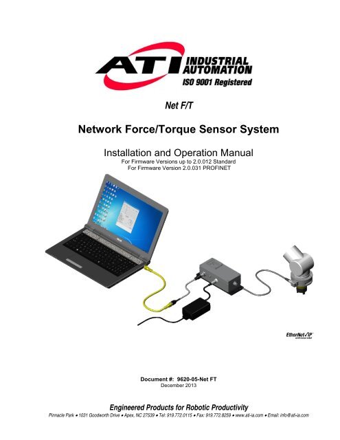
Network Force/Torque Sensor System
Net F/T Manual - ATI Industrial Automation
Net F/T Manual - ATI Industrial Automation

Create successful ePaper yourself
Turn your PDF publications into a flip-book with our unique Google optimized e-Paper software.
Net F/T<br />
<strong>Network</strong> <strong>Force</strong>/<strong>Torque</strong> <strong>Sensor</strong> <strong>System</strong><br />
Installation and Operation Manual<br />
For Firmware Versions up to 2.0.012 Standard<br />
For Firmware Version 2.0.031 PROFINET<br />
Document #: 9620-05-Net FT<br />
December 2013<br />
Engineered Products for Robotic Productivity<br />
Pinnacle Park • 1031 Goodworth Drive • Apex, NC 27539 • Tel: 919.772.0115 • Fax: 919.772.8259 • www.ati-ia.com • Email: info@ati-ia.com
Net F/T Installation and Operation Manual<br />
Document: 9620-05-net ft-11<br />
Foreword<br />
Information contained in this document is the property of ATI Industrial Automation, Inc. and shall not be reproduced in<br />
whole or in part without prior written approval of ATI Industrial Automation, Inc. The information herein is subject to change<br />
without notice and should not be construed as a commitment of ATI Industrial Automation, Inc. This manual is periodically<br />
revised to reflect and incorporate changes made to the F/T system.<br />
ATI Industrial Automation, Inc. assumes no responsibility for any errors or omissions in this document.<br />
Copyright © by ATI Industrial Automation, Inc., Apex, North Carolina USA. All Rights Reserved. Published in the USA.<br />
In consideration that ATI Industrial Automation, Inc. (ATI) products are intended for use with robotic and/or automated<br />
machines, ATI does not recommend the use of its products for applications wherein failure or malfunction of an ATI<br />
component or system threatens life or makes injury probable. Anyone who uses or incorporates ATI components within any<br />
potentially life-threatening system must obtain ATI’s prior consent based upon assurance to ATI that a malfunction of ATI’s<br />
component does not pose direct or indirect threat of injury or death, and (even if such consent is given) shall indemnify ATI<br />
from any claim, loss, liability, and related expenses arising from any injury or death resulting from use of ATI components.<br />
All trademarks belong to their respective owners.<br />
Windows is a registered trademark of Microsoft Corporation.<br />
NOTICE: Please read the F/T manuals before calling customer service. When calling, have<br />
the following information available:<br />
1. Serial number(s).<br />
2. Transducer type (e.g., Nano17, Gamma, Theta).<br />
3. Calibration (e.g., US-15-50, SI-130-10).<br />
4. An accurate and complete description of the question or problem.<br />
5. All information that is displayed on Net F/T page <strong>System</strong> Info (manuf.htm).<br />
If possible, the F/T system should be accessible when talking with an ATI Industrial<br />
Automation customer service representative.<br />
FCC Compliance - Class A<br />
This device complies with Part 15 Subpart B of the FCC Title 47. Operation is subject to the following two conditions: (1) this<br />
device may not cause harmful interference, and (2) this device must accept any interference received, including interference that may<br />
cause undesired operation.<br />
CE Conformity<br />
This device complies with EMC Directive 2004/108/EC and conforms to the following standards: EN55022:1998+A1:2000<br />
+A2:2003, EN61000-4-2:1995 +A1:1998+A2:2001, EN61000-4-3:2002, EN61000-4-4:2004, EN61000-4-5:1995 +A1:1996,<br />
EN61000-4-6:1996 +A1:2001, EN61000-4-8:1995, EN61000-4-11:2001.<br />
How to Reach Us<br />
Sales, Service and Information about ATI products:<br />
ATI Industrial Automation<br />
1031 Goodworth Drive<br />
Apex, NC 27539 USA<br />
www.ati-ia.com<br />
Tel: +1.919.772.0115<br />
Fax: +1.919.772.8259<br />
E-mail: info@ati-ia.com<br />
Technical support and questions:<br />
Application Engineering<br />
Tel: +1.919.772.0115, Option 2, Option 2<br />
Fax: +1.919.772.8259<br />
E-mail: ft_support@ati-ia.com<br />
Pinnacle Park • 1031 Goodworth Drive • Apex, NC 27539 USA • Tel: +1.919.772.0115 • Fax: +1.919.772.8259 • www.ati-ia.com • Email: info@ati-ia.com<br />
B - 2
Net F/T Installation and Operation Manual<br />
Document: 9620-05-net ft-11<br />
Statement of Compliance<br />
Pinnacle Park • 1031 Goodworth Drive • Apex, NC 27539 USA • Tel: +1.919.772.0115 • Fax: +1.919.772.8259 • www.ati-ia.com • Email: info@ati-ia.com<br />
B - 3
Net F/T Installation and Operation Manual<br />
Document: 9620-05-net ft-11<br />
Table of Contents<br />
Foreword ..................................................................................................................................... 2<br />
Statement of Compliance ........................................................................................................... 3<br />
Table of Contents ........................................................................................................................ 4<br />
Glossary ...................................................................................................................................... 9<br />
Definitions ................................................................................................................................... 9<br />
1. Safety ................................................................................................................................ 11<br />
1.1 General ........................................................................................................................................ 11<br />
1.2 Explanation of Notifications ......................................................................................................... 11<br />
1.3 Precautions ................................................................................................................................. 11<br />
2. <strong>System</strong> Overview .............................................................................................................. 12<br />
2.1 Multiple Calibrations .................................................................................................................... 12<br />
2.2 Multiple Configurations ................................................................................................................ 12<br />
2.3 <strong>Force</strong> and <strong>Torque</strong> Values ............................................................................................................ 12<br />
2.4 <strong>System</strong> Status Code .................................................................................................................... 12<br />
2.5 Thresholding ................................................................................................................................ 12<br />
2.6 Tool Transformations .................................................................................................................. 12<br />
2.7 Multiple Interfaces ....................................................................................................................... 12<br />
2.8 Power Supply .............................................................................................................................. 12<br />
3. Getting Started ................................................................................................................. 13<br />
3.1 Introduction .................................................................................................................................. 13<br />
3.2 Unpacking ................................................................................................................................... 13<br />
3.3 <strong>System</strong> Components Description ................................................................................................ 13<br />
3.3.1 F/T Transducer ............................................................................................................... 14<br />
3.3.2 Transducer Cable ........................................................................................................... 15<br />
3.3.3 Net Box ........................................................................................................................... 15<br />
3.4 Connecting the <strong>System</strong> Components .......................................................................................... 16<br />
3.4.1 Connecting the Transducer to the Net Box .................................................................... 16<br />
3.4.2 Providing Power to the Net F/T ...................................................................................... 16<br />
3.4.2.1 Method 1: Providing Power with PoE .............................................................. 16<br />
3.4.2.2 Method 2: Providing Power to Pwr/CAN Input ................................................ 17<br />
3.4.3 Connecting to Ethernet................................................................................................... 18<br />
3.4.3.1 Option 1: Connect to an Ethernet <strong>Network</strong> ...................................................... 19<br />
3.4.3.2 Option 2: Connect directly to a Computer’s Ethernet Interface ....................... 19<br />
3.5 IP Address Configuration for Ethernet ........................................................................................ 20<br />
3.6 Connecting to Ethernet using a Windows Computer .................................................................. 20<br />
3.6.1 Windows Vista and Windows 7 ...................................................................................... 21<br />
3.6.2 Windows XP ................................................................................................................... 21<br />
3.7 Connecting to an Ethernet-based Fieldbus ................................................................................. 24<br />
3.8 Connecting to DeviceNet (using DeviceNet-Compatibility Mode) ............................................... 24<br />
3.9 Connecting the Net Box to a CAN Bus <strong>Network</strong> ......................................................................... 24<br />
3.10 DIP Switches and Termination Resistor ...................................................................................... 24<br />
3.10.1 Termination Resistor ...................................................................................................... 25<br />
Pinnacle Park • 1031 Goodworth Drive • Apex, NC 27539 USA • Tel: +1.919.772.0115 • Fax: +1.919.772.8259 • www.ati-ia.com • Email: info@ati-ia.com<br />
B - 4
Net F/T Installation and Operation Manual<br />
Document: 9620-05-net ft-11<br />
3.10.2 Node Address ................................................................................................................. 25<br />
3.10.3 Baud Rate ...................................................................................................................... 27<br />
3.11 Status LEDs ................................................................................................................................ 27<br />
3.12 Power-Up Cycle .......................................................................................................................... 28<br />
4. Web Pages ........................................................................................................................ 30<br />
4.1 Introduction .................................................................................................................................. 30<br />
4.2 Welcome Page (index.htm)......................................................................................................... 30<br />
4.3 Snapshot Page (rundata.htm) ..................................................................................................... 31<br />
4.4 Demo Page (demo.htm) .............................................................................................................. 33<br />
4.5 Settings Page (setting.htm) ......................................................................................................... 34<br />
4.6 Thresholding Page (moncon.htm) ............................................................................................... 35<br />
4.6.1 Threshold Relay ............................................................................................................. 37<br />
4.6.1.1 Standard Net Box Threshold Relay ................................................................. 37<br />
4.6.1.2 Fieldbus Net Box and Optional Solid State Threshold Relay .......................... 39<br />
4.7 Configurations Page (config.htm) ................................................................................................ 41<br />
4.8 Communication Settings Page (comm.htm)................................................................................ 45<br />
4.9 <strong>System</strong> Information Page (manuf.htm) ....................................................................................... 48<br />
4.10 ATI Web Site Menu Item ............................................................................................................. 48<br />
5. Java Demo Application .................................................................................................... 49<br />
5.1 Starting the Demo ....................................................................................................................... 49<br />
5.2 Data Display with the Demo ........................................................................................................ 50<br />
5.3 Collecting Data with the Demo .................................................................................................... 51<br />
5.4 The Errors Display of the Demo .................................................................................................. 53<br />
5.5 Developing Your Own Java Application ...................................................................................... 54<br />
6. Net F/T Configuration Utility ............................................................................................ 55<br />
6.1 Finding Net F/Ts on the <strong>Network</strong> ................................................................................................ 55<br />
6.2 Backing Up a Configuration to a Computer................................................................................. 57<br />
6.3 Restoring a Saved Configuration ................................................................................................ 57<br />
6.4 Inspecting a Saved Configuration File ........................................................................................ 58<br />
7. Net F/T iPad Application .................................................................................................. 59<br />
7.1 Monitoring and Data Collection ................................................................................................... 59<br />
7.2 Exporting Data ............................................................................................................................. 61<br />
7.3 Data Collection Settings .............................................................................................................. 62<br />
8. Common Gateway Interface (CGI) ................................................................................... 64<br />
8.1 Settings CGI (setting.cgi) ............................................................................................................ 65<br />
8.2 Thresholding CGI (moncon.cgi) .................................................................................................. 66<br />
8.3 Configurations CGI (config.cgi) ................................................................................................... 66<br />
8.4 Communications CGI (comm.cgi) ............................................................................................... 68<br />
9. <strong>System</strong> Settings XML Pages ............................................................................................ 69<br />
9.1 <strong>System</strong> and Configuration Information (netftapi2.xml) ................................................................ 69<br />
9.2 Calibration Information (netftcalapi.xml) ...................................................................................... 72<br />
10. UDP Interface Using RDT ................................................................................................. 73<br />
10.1 RDT Protocol ............................................................................................................................... 73<br />
10.2 Extended RDT Requests............................................................................................................. 74<br />
Pinnacle Park • 1031 Goodworth Drive • Apex, NC 27539 USA • Tel: +1.919.772.0115 • Fax: +1.919.772.8259 • www.ati-ia.com • Email: info@ati-ia.com<br />
B - 5
Net F/T Installation and Operation Manual<br />
Document: 9620-05-net ft-11<br />
10.3 Calculating F/T Values for RDT .................................................................................................. 75<br />
10.4 Multi-Unit Mode ........................................................................................................................... 75<br />
10.5 Multiple Clients ............................................................................................................................ 75<br />
10.6 Notes on UDP and RDT Mode .................................................................................................... 75<br />
10.7 Example Code ............................................................................................................................. 75<br />
11. TCP Interface .................................................................................................................... 76<br />
11.1 General ........................................................................................................................................ 76<br />
11.2 Command Codes ........................................................................................................................ 76<br />
11.3 Read F/T Command .................................................................................................................... 76<br />
11.4 Read F/T Response .................................................................................................................... 76<br />
11.5 Read Calibration Info Command ................................................................................................. 76<br />
11.6 Read Calibration Info Response ................................................................................................. 77<br />
11.7 Write Tool Transform Command ................................................................................................. 77<br />
11.8 Write Monitor Condition Command ............................................................................................. 78<br />
11.9 Write Response ........................................................................................................................... 78<br />
12. EtherNet/IP Operation ...................................................................................................... 79<br />
12.1 Overview...................................................................................................................................... 79<br />
12.2 Module and <strong>Network</strong> Status LED ................................................................................................ 79<br />
13. DeviceNet-Compatibility Mode Operation ....................................................................... 80<br />
13.1 Overview...................................................................................................................................... 80<br />
13.2 MAC ID ........................................................................................................................................ 80<br />
13.3 Baud Rate ................................................................................................................................... 80<br />
13.4 Module and <strong>Network</strong> Status LED ................................................................................................ 80<br />
13.5 EDS File ...................................................................................................................................... 80<br />
14. EtherNet/IP and DeviceNet CIP Model ............................................................................. 81<br />
14.1 Overview...................................................................................................................................... 81<br />
14.2 Calculating F/T Values for CIP .................................................................................................... 83<br />
14.2.1 EtherNet/IP ..................................................................................................................... 83<br />
14.2.2 DeviceNet ....................................................................................................................... 83<br />
14.3 Object Model ............................................................................................................................... 84<br />
14.3.1 Data Types ..................................................................................................................... 84<br />
14.3.2 Transducer Strain Gage Object (0x64—6 Instances) .................................................... 84<br />
14.3.3 Transducer <strong>Force</strong>/<strong>Torque</strong> Object (0x65—6 Instances) .................................................. 85<br />
14.3.4 Thresholding Output Object (0x66—1 Instance) ............................................................ 85<br />
14.3.5 <strong>System</strong> Status Object (0x67—1 Instance) ..................................................................... 86<br />
14.3.6 Configurations Object (0x71—16 Instances) ................................................................. 86<br />
14.3.7 Settings Object (0x72—1 Instance) ............................................................................... 87<br />
14.3.8 Thresholding Settings Object (0x73—32 Instances) ...................................................... 88<br />
15. CAN Bus Operation .......................................................................................................... 89<br />
15.1 Overview...................................................................................................................................... 89<br />
15.2 Protocol Description .................................................................................................................... 89<br />
15.3 Base Address and Communication Format ................................................................................ 89<br />
15.4 Baud Rate ................................................................................................................................... 90<br />
15.5 Calculating F/T Values for CAN .................................................................................................. 90<br />
Pinnacle Park • 1031 Goodworth Drive • Apex, NC 27539 USA • Tel: +1.919.772.0115 • Fax: +1.919.772.8259 • www.ati-ia.com • Email: info@ati-ia.com<br />
B - 6
Net F/T Installation and Operation Manual<br />
Document: 9620-05-net ft-11<br />
16. Fieldbus Operation ........................................................................................................... 91<br />
16.1 PROFINET Fieldbus Interface .................................................................................................... 91<br />
16.1.1 Enabling the PROFINET Interface ................................................................................. 92<br />
16.1.2 Communications CGI (comm.cgi) Options ..................................................................... 94<br />
16.1.3 XML Page Elements....................................................................................................... 94<br />
16.1.4 Returning Default Settings ............................................................................................. 94<br />
16.1.5 Replacing and Installed PROFINET Fieldbus Net Box .................................................. 94<br />
16.1.5.1 Replacement with an Uncommissioned Fieldbus Net Box .............................. 94<br />
16.1.5.2 Replacement with Previously Commissioned Fieldbus Net Box ..................... 95<br />
17. Advanced Topics .............................................................................................................. 96<br />
17.1 Improving Ethernet Throughput .................................................................................................. 96<br />
17.1.1 Direct Connection between Net F/T and Host ............................................................... 96<br />
17.1.2 Choice of Operating <strong>System</strong> .......................................................................................... 96<br />
17.1.3 Increasing Operating <strong>System</strong> Performance ................................................................... 96<br />
17.1.4 Avoid Logging the Host to a Company <strong>Network</strong> ............................................................ 96<br />
17.1.5 Use a Dedicated <strong>Network</strong> .............................................................................................. 96<br />
17.2 Reducing Noise ........................................................................................................................... 97<br />
17.2.1 Mechanical Vibration ...................................................................................................... 97<br />
17.2.2 Electrical Interference..................................................................................................... 97<br />
17.3 Detecting Failures (Diagnostics) ................................................................................................. 97<br />
17.3.1 Detecting Sensitivity Changes ....................................................................................... 97<br />
17.4 Scheduled Maintenance .............................................................................................................. 97<br />
17.4.1 Periodic Inspection ......................................................................................................... 97<br />
17.5 A Word about Resolution ............................................................................................................ 98<br />
17.6 Connecting to Specific Industrial Robots .................................................................................... 98<br />
17.6.1 ABB Robotics ................................................................................................................. 99<br />
17.6.2 Denso Robotics .............................................................................................................. 99<br />
17.6.3 Fanuc Robotics .............................................................................................................. 99<br />
17.6.4 Kuka Robotics .............................................................................................................. 100<br />
17.6.5 Motoman Robotics ....................................................................................................... 100<br />
18. Troubleshooting ............................................................................................................. 101<br />
18.1 Introduction ................................................................................................................................ 101<br />
18.2 <strong>System</strong> Status Code .................................................................................................................. 101<br />
18.3 Questions and Answers ............................................................................................................ 103<br />
18.3.1 Powering Up ................................................................................................................. 103<br />
18.3.2 Communications ........................................................................................................... 103<br />
18.3.3 Java Demo ................................................................................................................... 103<br />
18.3.4 Web Pages ................................................................................................................... 104<br />
18.3.5 Errors with <strong>Force</strong> and <strong>Torque</strong> Readings ...................................................................... 104<br />
18.3.6 Connection to Specific Equipment ............................................................................... 104<br />
19. General Specifications ................................................................................................... 105<br />
19.1 Environmental ........................................................................................................................... 105<br />
19.1.1 Storage and Operating Temperatures ......................................................................... 105<br />
19.2 Transducer Data Filtering .......................................................................................................... 105<br />
Pinnacle Park • 1031 Goodworth Drive • Apex, NC 27539 USA • Tel: +1.919.772.0115 • Fax: +1.919.772.8259 • www.ati-ia.com • Email: info@ati-ia.com<br />
B - 7
Net F/T Installation and Operation Manual<br />
Document: 9620-05-net ft-11<br />
19.3 Electrical Specifications ............................................................................................................. 106<br />
19.3.1 Power Supply ............................................................................................................... 106<br />
19.3.2 Communications ........................................................................................................... 106<br />
19.3.2.1 Ethernet Interface .......................................................................................... 106<br />
19.3.2.2 CAN Interface ................................................................................................ 107<br />
19.3.3 Mating Connectors ....................................................................................................... 107<br />
19.3.4 Standard Threshold Relay ........................................................................................... 107<br />
19.3.5 Solid-State Threshold Relay ........................................................................................ 107<br />
19.3.6 NetBox Transducer Cabling ......................................................................................... 108<br />
19.4 Net Box Weight ......................................................................................................................... 108<br />
20. Drawings ......................................................................................................................... 109<br />
20.1 9105-NETB Drawing ................................................................................................................. 109<br />
20.2 9105-NETBA Drawing ............................................................................................................... 110<br />
20.3 9105-NETB-PN2 Drawing ......................................................................................................... 111<br />
21. Terms and Conditions of Sale ....................................................................................... 113<br />
Pinnacle Park • 1031 Goodworth Drive • Apex, NC 27539 USA • Tel: +1.919.772.0115 • Fax: +1.919.772.8259 • www.ati-ia.com • Email: info@ati-ia.com<br />
B - 8
Net F/T Installation and Operation Manual<br />
Document: 9620-05-net ft-11<br />
Glossary<br />
Accuracy<br />
Terms<br />
Active Configuration<br />
Calibration<br />
CAN<br />
CGI<br />
Compound Loading<br />
Configuration<br />
Coordinate Frame<br />
DeviceNet<br />
DeviceNet Compatibility<br />
Mode<br />
DHCP<br />
Dup_MAC_ID test<br />
EtherNet/IP<br />
Ethernet <strong>Network</strong> Switch<br />
Fieldbus<br />
FS<br />
F/T<br />
Fxy<br />
Hysteresis<br />
IP Address<br />
IPV4<br />
Java<br />
MAC Address<br />
See Measurement Uncertainty.<br />
The configuration the system is currently using.<br />
Definitions<br />
The factory-supplied data used by Net F/T so it can report accurate transducer readings.<br />
Calibrations apply to a given loading range.<br />
Controller Area <strong>Network</strong> (CAN) is a low level communication protocol used in some networks,<br />
including DeviceNet. The Net F/T system has a simple CAN protocol that can be used to read<br />
force and torque values.<br />
Common Gateway Interface (CGI) is the method of using web URLs to communicate data<br />
and parameters back to a web device.<br />
Any force or torque load that is not purely in one axis.<br />
User-defined settings that include which force and torque units are reported, which calibration<br />
is to be used, and any tool transformation data.<br />
See Point of Origin.<br />
A Fieldbus communication network used mostly by devices in industrial settings, that<br />
communicates using CAN. DeviceNet is a trademark of ODVA.<br />
A feature of the Net F/T that allows it to respond like a certified DeviceNet device.<br />
Dynamic Host Configuration Protocol (DHCP) is an automatic method for Ethernet equipment<br />
to obtain an IP address. The Net F/T system can obtain its IP address using DHCP on<br />
networks that support this protocol.<br />
The Duplicate MAC ID test is performed by a DeviceNet node (device) at power up to verify<br />
its MAC ID (device address) is not in use by another device.<br />
EtherNet/IP (Ethernet Industrial Protocol) is a Fieldbus communication network, used mostly<br />
by devices in industrial settings, that communicates using Ethernet. EtherNet/IP is a<br />
trademark of ControlNet International Ltd. used under license by ODVA.<br />
Ethernet network switches are electronic devices that connect multiple Ethernet cables to an<br />
Ethernet network while directing the flow of traffic.<br />
A generic term referring to any one of a number of industrial computer networking standards.<br />
Examples include: CAN, Modbus, and PROFINET.<br />
Full-Scale.<br />
<strong>Force</strong> and <strong>Torque</strong>.<br />
The resultant force vector comprised of components Fx and Fy.<br />
A source of measurement caused by the residual effects of previously applied loads.<br />
An IP Address (Internet Protocol Address) is an electronic address assigned to an Ethernet<br />
device so that it may send and receive Ethernet data. IP addresses may be either manually<br />
selected by the user or automatically assigned by the DHCP protocol.<br />
IPV4 (Internet Protocol Version 4) describes IP addresses using four bytes, usually expressed<br />
in the dot-decimal notation, such as, 192.168.1.1 for example.<br />
Java is a programming language often used for programs on web pages. The Net F/T demo<br />
is a Java application. Java is a registered trademark of Sun Microsystems, Inc.<br />
MAC Addresses (Media Access Control Addresses) are the unique addresses given to every<br />
Ethernet device when it is manufactured, to be used as an electronic Ethernet serial number.<br />
Pinnacle Park • 1031 Goodworth Drive • Apex, NC 27539 USA • Tel: +1.919.772.0115 • Fax: +1.919.772.8259 • www.ati-ia.com • Email: info@ati-ia.com<br />
B - 9
Net F/T Installation and Operation Manual<br />
Document: 9620-05-net ft-11<br />
MAC ID<br />
Terms<br />
Maximum Single-Axis<br />
Overload<br />
MAP<br />
Measurement Uncertainty<br />
Net Box<br />
Node Address<br />
ODVA<br />
Overload<br />
PoE<br />
Point of Origin<br />
PROFINET<br />
Quantization<br />
RDT<br />
Resolution<br />
Saturation<br />
<strong>Sensor</strong> <strong>System</strong><br />
TAP<br />
TCP<br />
Thresholding<br />
Tool Transformation<br />
Transducer<br />
Txy<br />
UDP<br />
Definitions<br />
Media Access Code Identifier (MAC ID) is a unique number that is user assigned to each<br />
DeviceNet device on a DeviceNet network. Also called Node Address.<br />
The largest amount of pure load (not compound loading) that the transducer can withstand<br />
without damage.<br />
The Mounting Adapter Plate (MAP) is the transducer plate that attaches to the fixed surface or<br />
robot arm.<br />
The maximum expected error in measurements, as specified on the calibration certificate.<br />
The component that contains the power supply and network interfaces of the Net F/T system.<br />
See MAC ID.<br />
ODVA (Open DeviceNet Vendors Association, Inc.) is an organization that defines DeviceNet,<br />
EtherNet/IP, and other industrial networks. ATI Industrial Automation is a member of ODVA.<br />
ODVA is a registered trademark of Open DeviceNet Vendors Association, Inc.<br />
The condition where more load is applied to the transducer than it can measure. This will<br />
result in saturation.<br />
Power-over-Ethernet, or PoE, is a method of delivering electrical power to a PoE-compatible<br />
Ethernet device through the Ethernet cable. This simplifies installation of the Ethernet device<br />
since a separate power supply is not needed. The Net F/T system is PoE compatible.<br />
The location on the transducer from which all forces and torques are measured. Also known<br />
as the Coordinate Frame.<br />
An Ethernet-based fieldbus used in factory automation.<br />
The process of converting a continuously variable transducer signal into discrete digital<br />
values. Usually used when describing the change from one digital value to the next increment.<br />
Raw Data Transfer (RDT) is a fast and simple Net F/T protocol for control and data transfer<br />
via UDP.<br />
The smallest change in load that can be measured. This is usually much smaller than<br />
accuracy.<br />
The condition where the transducer has a load outside of its sensing range.<br />
The assembly consisting of all components from the transducer to the Net Box.<br />
Tool Adapter Plate (TAP) is the transducer surface that attaches to the load to be measured.<br />
Transmission Control Protocol (TCP) is a low-level method of transmitting data over Ethernet.<br />
TCP provides a slower, more reliable delivery of data than UDP.<br />
A Net F/T function that performs a simple arithmetic comparison of a user-defined threshold to<br />
the loading on a transducer axis.<br />
A method of mathematically shifting the measurement coordinate system to translate the point<br />
of origin and/or rotate its axes.<br />
Transducer is the component that converts the sensed load into electrical signals.<br />
The resultant torque vector comprised of components Tx and Ty.<br />
UDP (User Datagram Protocol) is a low-level method of transmitting data over Ethernet. While<br />
UDP is faster than TCP, unlike TCP lost UDP data is not resent.<br />
Pinnacle Park • 1031 Goodworth Drive • Apex, NC 27539 USA • Tel: +1.919.772.0115 • Fax: +1.919.772.8259 • www.ati-ia.com • Email: info@ati-ia.com<br />
B - 10
Net F/T Installation and Operation Manual<br />
Document: 9620-05-net ft-11<br />
1. Safety<br />
1.1 General<br />
The customer should verify that the transducer selected is rated for maximum loads and moments<br />
expected during operation. Refer to transducer specifications in F/T Transducer Manual (9620-05-<br />
Transducer Section—Installation and Operation Manual) or contact ATI Industrial Automation for<br />
assistance. Particular attention should be paid to dynamic loads caused by robot acceleration and<br />
deceleration. These forces can be many times the value of static forces in high acceleration or<br />
deceleration situations.<br />
1.2 Explanation of Notifications<br />
The notifications included here are specific to the product(s) covered by this manual. It is expected that<br />
the user heed all notifications from the robot manufacturer and/or the manufacturers of other components<br />
used in the installation.<br />
or<br />
DANGER: Notification of information or instructions that if not followed will result<br />
in death or serious injury. The notification provides information about the nature of<br />
the hazardous situation, the consequences of not avoiding the hazard, and the<br />
method for avoiding the situation.<br />
WARNING: Notification of information or instructions that if not followed could<br />
result in death or serious injury. The notification provides information about the<br />
nature of the hazardous situation, the consequences of not avoiding the hazard,<br />
and the method for avoiding the situation.<br />
CAUTION: Notification of information or instructions that if not followed could<br />
result in moderate injury or will cause damage to equipment. The notification<br />
provides information about the nature of the hazardous situation, the<br />
consequences of not avoiding the hazard, and the method for avoiding the<br />
situation.<br />
ATTENTION, NOTE, or NOTICE: Notification of specific information or instructions about<br />
maintaining, operating, installation, or setup of the product that if not followed could result in<br />
damage to equipment. The notification can emphasize but is not limited to specific grease<br />
types, good operating practices, or maintenance tips.<br />
1.3 Precautions<br />
CAUTION: Do not remove any fasteners or disassemble transducers without a<br />
removable adapter plate, these include Nono, Mini, IP-rated, and some Omega<br />
transducers. This will cause irreparable damage to the transducer and void the<br />
warranty. Leave all fasteners in place and do not disassemble the transducer.<br />
CAUTION: Do not probe any opening in the transducer. Touching internal<br />
electronics or instrumentation could damage the transducer and void the warranty.<br />
CAUTION: Do not exceed the transducer’s overload ratings. Smaller Nano and<br />
Mini transducers can easily be irreparably damaged by apply small loads using<br />
tools (moment arm increases applied loads) when mounting the transducer. Always<br />
monitor the transducer using the demo application for gage saturation errors during<br />
installation.<br />
Pinnacle Park • 1031 Goodworth Drive • Apex, NC 27539 USA • Tel: +1.919.772.0115 • Fax: +1.919.772.8259 • www.ati-ia.com • Email: info@ati-ia.com<br />
B - 11
Net F/T Installation and Operation Manual<br />
Document: 9620-05-net ft-11<br />
2. <strong>System</strong> Overview<br />
The <strong>Network</strong> <strong>Force</strong>/<strong>Torque</strong> (Net F/T) sensor system is a multi-axis force and torque sensor system that<br />
simultaneously measures forces Fx, Fy, and Fz and torques Tx, Ty, and Tz. The Net F/T system communicates<br />
via EtherNet/IP, CAN Bus, Ethernet, and is compatible with DeviceNet. Optional fieldbus interfaces are also<br />
available. The Net F/T’s web pages make it easy to set up and monitor.<br />
The Net F/T system supports the following features:<br />
2.1 Multiple Calibrations<br />
The Net F/T can hold up to sixteen different transducer calibrations and each can have a different sensing<br />
range. The different calibrations are created with different load scenarios during the calibration process at<br />
the factory and stored in the Net F/T.<br />
Multiple calibrations allow you to use a larger calibration for coarse adjustments and smaller calibrations<br />
for fine adjustments, or to use the same transducer in two or more very different loading regimes.<br />
Contact ATI Industrial Automation for information on obtaining additional transducer calibrations.<br />
The calibration to use is determined by the calibration selected in the active configuration.<br />
2.2 Multiple Configurations<br />
The Net F/T also holds up to sixteen different user configurations. Each configuration is linked to a userselected<br />
calibration and may have its own tool transformation. Configurations are useful when the Net<br />
F/T is used in a variety of tasks. The currently active configuration is user selected on the Net F/T’s<br />
Settings web page.<br />
2.3 <strong>Force</strong> and <strong>Torque</strong> Values<br />
The Net F/T outputs scaled numbers, or counts, that represent the loading of each force and torque axis.<br />
The number of counts per force unit and counts per torque unit is specified by the calibration. If you wish<br />
to use different force and torque units (i.e., your transducer is calibrated to use pounds and pound-inches,<br />
but you wish to use Newtons and Newton-meters), you can change the output units on the Net F/T’s<br />
Configurations web page.<br />
2.4 <strong>System</strong> Status Code<br />
Each Net F/T output data record contains a system status code which indicates the health of the<br />
transducer and the Net Box. See Section 18.2—<strong>System</strong> Status Code for details.<br />
2.5 Thresholding<br />
The Net F/T is capable of monitoring the force and torque levels of each axis and setting an output code<br />
if a reading crosses a threshold you define. The Net F/T can hold up to sixteen thresholds, and each<br />
threshold can be enabled and disabled individually or as a group. You can set up thresholding on the Net<br />
F/T’s Thresholding web page.<br />
2.6 Tool Transformations<br />
The Net F/T is capable of measuring the forces and torques acting at a point other than the factorydefined<br />
point-of-origin (also known as the sensing reference frame origin). This change of reference is<br />
called a tool transformation. You specify tool transformations for each configuration on the Net F/T’s<br />
Configurations web page.<br />
2.7 Multiple Interfaces<br />
The Net F/T system communicates via EtherNet/IP, CAN bus, Ethernet, and is compatible with<br />
DeviceNet. Each of these interfaces can be enabled and disabled on the Net F/T’s Communications web<br />
page.<br />
2.8 Power Supply<br />
The Net F/T system accepts power through PoE (Power-over-Ethernet) or from a DC power source with<br />
an output voltage between 11V and 24V.<br />
Pinnacle Park • 1031 Goodworth Drive • Apex, NC 27539 USA • Tel: +1.919.772.0115 • Fax: +1.919.772.8259 • www.ati-ia.com • Email: info@ati-ia.com<br />
B - 12
Net F/T Installation and Operation Manual<br />
Document: 9620-05-net ft-11<br />
3. Getting Started<br />
3.1 Introduction<br />
This section gives instructions for setting up the Net F/T system.<br />
3.2 Unpacking<br />
• Check the shipping container and components for damage that occurred during shipping. Any<br />
damage should be reported to ATI Industrial Automation.<br />
• Check the packing list for omissions.<br />
• Standard components of a Net F/T system are:<br />
- Net F/T Transducer<br />
- Transducer cable (which may be integral to the transducer)<br />
- Net Box<br />
- ATI Industrial Automation CD containing software, calibration documents, and manuals<br />
(including this manual).<br />
• Optional components:<br />
- Power supply: Plugs into a 100–240 VAC (50–60Hz) power outlet and supplies power to<br />
the Net Box through the Pwr/CAN connector<br />
- Ethernet switch supporting Power-over-Ethernet: Provides network connection and supplies<br />
power over the Ethernet connector<br />
- RJ45 to M12 Ethernet cable adapter<br />
- Mini to Micro (M12) DeviceNet adapter (for the Pwr/CAN connector)<br />
- DeviceNet cabling (for the Pwr/CAN connector)<br />
- Ethernet cabling<br />
- Robot-grade transducer cables of different lengths.<br />
3.3 <strong>System</strong> Components Description<br />
The Net F/T sensor system is a multi-axis force and torque sensor system that simultaneously measures<br />
forces Fx, Fy, Fz, and torques Tx, Ty, and Tz. The Net F/T system provides EtherNet/IP, CAN bus, and<br />
Ethernet communication interfaces and is compatible with DeviceNet.<br />
In Figure 3.1, the main components of the Net F/T system are displayed.<br />
The Net F/T Transducer converts the force and torque loads into electrical signals and transmits them<br />
over the transducer cable. With the exception of very tiny transducers, like the Nano and Mini series, the<br />
signals are digital. The Nano and Mini series transducers are too small for on-board electronics and<br />
transmit analog signals.<br />
The Transducer Cable is detachable and replaceable on transducers that use digital transmission. On<br />
other transducers, like the tiny Nano and Mini series, the transducer cable is an integral part of transducer<br />
and cannot be detached.<br />
The Net Box is an IP65-rated aluminum housing that contains the power supplies and network interfaces.<br />
A digital-input version of the Net Box (NETB) is used with digital transducers while an analog-input<br />
version of the Net Box (NETBA) is used with analog transducers.<br />
Pinnacle Park • 1031 Goodworth Drive • Apex, NC 27539 USA • Tel: +1.919.772.0115 • Fax: +1.919.772.8259 • www.ati-ia.com • Email: info@ati-ia.com<br />
B - 13
Net F/T Installation and Operation Manual<br />
Document: 9620-05-net ft-11<br />
Figure 3.1—Net F/T <strong>System</strong> Components<br />
3.3.1 F/T Transducer<br />
The transducer is a compact, rugged, monolithic structure that senses forces and torques.<br />
The F/T transducer is commonly used as a wrist transducer mounted between a robot and a<br />
robot end-effector. Figure 3.2 shows a sample transducer.<br />
• For further information not in this section, refer to F/T Transducer Manual (9620-05-<br />
Transducer Section—Installation and Operation Manual.)<br />
Figure 3.2—Sample Transducer (Omega160)<br />
NOTICE: The transducer is<br />
designed to withstand<br />
extremely high overloading<br />
because of its construction<br />
using strong materials and<br />
quality silicon strain gages.<br />
Pinnacle Park • 1031 Goodworth Drive • Apex, NC 27539 USA • Tel: +1.919.772.0115 • Fax: +1.919.772.8259 • www.ati-ia.com • Email: info@ati-ia.com<br />
B - 14
Net F/T Installation and Operation Manual<br />
Document: 9620-05-net ft-11<br />
3.3.2 Transducer Cable<br />
The Transducer Cable delivers power from the Net Box to the transducer and transmits the<br />
transducer’s strain gage data back to the Net Box.<br />
Transducers with on-board electronics (ATI Industrial Automation part number prefix 9105-<br />
NET) are connected to the Net Box (ATI Industrial Automation part number prefix 9105-<br />
NETB) via industry standard M12 Micro DeviceNet cabling. Any DeviceNet-compatible cable<br />
with correct gender M12 Micro connectors can be used, but non-IP rated transducers are not<br />
compatible with right-angled connectors. ATI Industrial Automation supplies a robotic grade<br />
high-flex transducer cable with each Net F/T system. Many other DeviceNet cable choices are<br />
available to address different requirements. In case of special requirements, contact ATI<br />
Industrial Automation or an industrial cable manufacturer (see www.turck.com,<br />
www.woodhead.com, and others) for available products.<br />
ATI’s 9105-C-MTS-MS cables can be connected to each other to make a multi-section cable.<br />
Transducers that do not have on-board electronics (ATI Industrial Automation part number<br />
prefix 9105-TW) usually have integral cabling. Those that require cabling must use an ATI<br />
Industrial Automation cable specifically made for these transducers. Transducers without the<br />
on-board electronics connect to Net Box version 9105-NETBA.<br />
The transducer can be used in a variety of applications that will affect how best to route the<br />
cable and determine the proper bending radius to use. Some applications will allow the<br />
transducer and the cable to remain in a static condition, other applications require the<br />
transducer to be in a dynamic condition that requires the cable to be subjected to repetitive<br />
motion. It is important not to expose the transducer cable connectors to this repetitive motion,<br />
and properly restrain the cable close the transducer connection. Refer to (9620-05 Transducer<br />
Section) manual for proper cable routing and bending radius instructions.<br />
3.3.3 Net Box<br />
WARNING: Transducers are not compatible with DeviceNet. Do not<br />
attempt to directly connect a transducer to a DeviceNet network.<br />
Transducers must be connected to a Net Box.<br />
NOTICE: If a transducer is accidentally connected to a DeviceNet network, neither<br />
the transducer nor the network will be physically harmed. Communication errors<br />
may occur on the DeviceNet network while the transducer is connected.<br />
CAUTION: Do not subject the transducer cable connector to the<br />
repetitive motion of the robot or other device. Subjecting the connector to<br />
the repetitive motion will cause damage to the connector. Restrain the<br />
cable close to the connector to keep the repetitive motion of the robot<br />
from affecting the cable connector.<br />
The primary function of the Net Box is to process and communicate the transducer’s force and<br />
torque readings to the user’s equipment. Communication can be done through Ethernet,<br />
EtherNet/IP, and CAN Bus. The Net Box also responds to DeviceNet commands sent over the<br />
CAN Bus connection.<br />
The Net Box should be mounted in an area that it is not exposed to temperatures outside of its<br />
working range (see Section 19.1—Environmental). It is designed to be used indoors in a nondynamic,<br />
non-vibratory environment and may be mounted in any orientation. It is designed to<br />
meet IP65 ingress protection.<br />
The Net Box should be grounded through at least one of the four mounting tabs.<br />
Pinnacle Park • 1031 Goodworth Drive • Apex, NC 27539 USA • Tel: +1.919.772.0115 • Fax: +1.919.772.8259 • www.ati-ia.com • Email: info@ati-ia.com<br />
B - 15
Net F/T Installation and Operation Manual<br />
Document: 9620-05-net ft-11<br />
The Net Box receives power through either a standard PoE (Power-over-Ethernet) switch or<br />
the Pwr/CAN connector.<br />
3.4 Connecting the <strong>System</strong> Components<br />
3.4.1 Connecting the Transducer to the Net Box<br />
The Net F/T system normally ships with an off-the-shelf M12 DeviceNet cable to connect the<br />
transducer to the Net Box.<br />
Plug the female M12 connector of this cable into the male M12 socket of the transducer. Then<br />
tighten its sleeve clockwise to lock the connector. See Section 19.3.3–Mating Connectors for<br />
recommended connector torque levels.<br />
Figure 3.3—Connecting Transducer Cable to Transducer<br />
Plug the male M12 connector into the female M12 socket marked Transducer. Then turn its<br />
sleeve in a clockwise direction until tightened to lock it to the socket. See Section 19.3.3—<br />
Mating Connectors for recommended connector torque levels.<br />
Figure 3.4—Connecting Transducer Cable to Net Box<br />
To avoid disturbed transducer signals, especially in a noisy environment and when using long<br />
transducer cables, it is highly recommended to provide a low impedance ground connection for<br />
the transducer body.<br />
3.4.2 Providing Power to the Net F/T<br />
There are two ways to provide power to a standard Net F/T. Net F/Ts with an optional fieldbus<br />
interface do not support PoE and must use an external power source (Method 2).<br />
3.4.2.1 Method 1: Providing Power with PoE<br />
NOTICE: Power-over-Ethernet is not supported by Net F/Ts that have an<br />
optional fieldbus.<br />
The Net F/T’s Power over Ethernet input is compatible with IEEE 802.3af (Power<br />
over Ethernet) specification and uses Mode A to receive power. Mode B requires<br />
eight Ethernet conductors and is not supported.<br />
Pinnacle Park • 1031 Goodworth Drive • Apex, NC 27539 USA • Tel: +1.919.772.0115 • Fax: +1.919.772.8259 • www.ati-ia.com • Email: info@ati-ia.com<br />
B - 16
Net F/T Installation and Operation Manual<br />
Document: 9620-05-net ft-11<br />
The Net F/T system optionally ships with a PoE Ethernet switch. ATI Industrial<br />
Automation part number 9105-POESWITCH-1 (see Figure 3.5—Connecting to the<br />
Ethernet), which provides PoE (Power-over-Ethernet) on four ports with RJ45<br />
receptacles. Any PoE enabled device can get its power supply and communication<br />
signals from one of these ports. Any non-PoE device connected to these ports will<br />
receive an Ethernet connection without the power delivery. The Net F/T system<br />
accepts PoE and thus only needs one cable connection to function on an Ethernet<br />
network.<br />
• Connect the PoE switch to its external AC power supply.<br />
• Connect the AC power supply to the AC mains. The PWR LED should turn<br />
on and glow green.<br />
• Connect the PoE switch to your Ethernet network and connect the Net Box<br />
via RJ45 cable to one of the PoE ports. See Section 3.4.3—Connecting to<br />
Ethernet for information on making an Ethernet connection.<br />
Figure 3.5—Connecting to the Ethernet<br />
Once the Net Box is connected to the PoE switch, it should start up, first with red<br />
and green blinking LEDs. After approximately 20 seconds all LEDs should be<br />
green.<br />
NOTICE: If power is not provided to the Pwr/CAN connection then CAN<br />
bus baud rate, CAN bus base address, and DeviceNet MAC IDs are not<br />
correctly reported and communications over the Pwr/CAN connector are<br />
not available.<br />
3.4.2.2 Method 2: Providing Power to Pwr/CAN Input<br />
Instead of supplying power with the PoE option, you can use the 11V to 24V DC<br />
power input of the M12 Pwr/CAN connector. See Section 19.3.3—Mating<br />
Connectors for recommended connector torque levels.<br />
Pinnacle Park • 1031 Goodworth Drive • Apex, NC 27539 USA • Tel: +1.919.772.0115 • Fax: +1.919.772.8259 • www.ati-ia.com • Email: info@ati-ia.com<br />
B - 17
Net F/T Installation and Operation Manual<br />
Document: 9620-05-net ft-11<br />
Figure 3.6—Pwr/CAN Micro Connector (view from male pin side)<br />
The Net F/T may ship with an optional power adapter (ATI PN 9105-NETPS) that<br />
directly connects to the Pwr/CAN connector and delivers sufficient power for the<br />
Net F/T system.<br />
Instead of using this power adapter, you can connect to your own DC power source<br />
as long as you provide sufficient voltage and current (see Section 19.3.3—Mating<br />
Connectors for details) to the V+, V- inputs of the Pwr/CAN connector. ATI<br />
Industrial Automation offers an optional M12 female connector with screw<br />
terminals (ATI PN 1510-2312000-05) for field wiring to connect to your power<br />
source. Please note that although the connector provides access to CAN_H, CAN_L,<br />
and Drain connections, these pins should be left unconnected if they are not being<br />
used for CAN communications.<br />
Figure 3.7—DC Power Source Connection (Using Pwr/CAN Connector)<br />
3.4.3 Connecting to Ethernet<br />
This section describes how to physically connect to Ethernet. See Section 3.5—IP Address<br />
Configuration for Ethernet for information on configuring your Net F/T’s Ethernet settings and<br />
Section 3.6—Connecting to Ethernet using a Windows Computer for information on<br />
configuring a Windows XP or Windows Vista computer.<br />
An industrial M12-4 Type-D Connector is provided for Ethernet connection. See Section<br />
19.3.3—Mating Connectors for recommended connector torque levels. The Net F/T system<br />
optionally ships with an off-the-shelf M12 Industrial Ethernet cable and/or an M12 to RJ45<br />
adapter. The adapter allows the use of standard office-grade Ethernet cables with RJ45<br />
connectors.<br />
Pinnacle Park • 1031 Goodworth Drive • Apex, NC 27539 USA • Tel: +1.919.772.0115 • Fax: +1.919.772.8259 • www.ati-ia.com • Email: info@ati-ia.com<br />
B - 18
Net F/T Installation and Operation Manual<br />
Document: 9620-05-net ft-11<br />
Figure 3.8—Ethernet M12-4, Type-D Connector (view from female pin side)<br />
There are two ways that the Net Box can connect to Ethernet.<br />
NOTICE: To achieve the best Ethernet performance (and to reduce the likelihood<br />
of loosing data), we recommend connecting the Net Box directly to the host<br />
computer, as described in Option 2.<br />
3.4.3.1 Option 1: Connect to an Ethernet <strong>Network</strong><br />
Use the M12 to RJ45 adapter to connect a standard RJ45 Ethernet cable to the Net<br />
Box. Be certain to tighten the sleeve fully clockwise to lock the connector.<br />
Plug the other end of the Ethernet cable into the port of an Ethernet switch. See<br />
Figure 3.8—Connecting to Ethernet for a proposed setup.<br />
Figure 3.9—Connecting to Ethernet<br />
3.4.3.2 Option 2: Connect directly to a Computer’s Ethernet Interface<br />
The Net F/T system is connected directly to a computer’s Ethernet port via a cable<br />
and is not connected to an Ethernet switch. Use the M12 to RJ45 adapter to connect<br />
a standard RJ45 Ethernet cable to the Net box. The most basic configuration would<br />
be a point-to-point connection between a computer’s Ethernet interface and the Net<br />
F/T’s Ethernet interface (see Figure 3.9—Point-to-Point Ethernet Connection). In<br />
this case, power has to be provided via the Pwr/CAN connector (see Section<br />
3.4.2.2—Method 2: Providing Power to Pwr/CAN Input for details). This<br />
configuration has the lowest latency and lowest chance of lost data packages and<br />
provides the best high-speed connection.<br />
If necessary, the computer may be connected to an Ethernet network via a second<br />
Ethernet port on the computer. Note that most computers do not have a second<br />
Ethernet port and one may need to be installed. Doing so is outside the scope of this<br />
document. Contact your IT department for assistance.<br />
Pinnacle Park • 1031 Goodworth Drive • Apex, NC 27539 USA • Tel: +1.919.772.0115 • Fax: +1.919.772.8259 • www.ati-ia.com • Email: info@ati-ia.com<br />
B - 19
Net F/T Installation and Operation Manual<br />
Document: 9620-05-net ft-11<br />
Figure 3.10—Point-to-Point Ethernet Connection<br />
3.5 IP Address Configuration for Ethernet<br />
The Net F/T system’s IP address settings are only loaded upon power up, consequently the Net F/T must<br />
be power cycled for new IP address setting changes to be used. There are three ways the Net F/T<br />
system’s IP address can be configured.<br />
Method 1:<br />
Method 2:<br />
Method 3:<br />
Set IP address 192.168.1.1 by setting DIP switch 9 to the ON position.<br />
Set IP address to a static value stored on the Net F/T’s Communication Settings web<br />
page (DIP switch 9 must be in the OFF position). This method is described in Section<br />
3.6—Connecting to Ethernet using a Windows Computer.<br />
Let a DHCP server take care of the IP address assignment (DIP switch 9 must be in the<br />
OFF position). This option can be enabled in the Net F/T’s web pages (see Section<br />
3.6—Connecting to Ethernet using a Windows Computer for details). To use this<br />
method, a DHCP server must be present in the network. This is usually the case in<br />
company networks.<br />
The Net F/T is shipped with DHCP enabled and the static IP address set to 192.168.1.1. The static IP<br />
address is automatically used if the network does not support DHCP. DHCP will not be used if a LAN<br />
connection is absent during power up.<br />
3.6 Connecting to Ethernet using a Windows Computer<br />
Most of the Ethernet configuration is performed via the Net F/T’s web pages. To initially access the web<br />
pages, you will need to configure your Net F/T to work on your network by getting it assigned an IP<br />
address and telling it some basic information about your network.<br />
For purposes of this initial connection, your computer will be connected directly to the Net F/T and<br />
disconnected from your LAN. You will be temporarily giving your computer a fixed IP address of<br />
192.168.1.100. It is important that the Ethernet cable to the Net F/T is disconnected from your computer<br />
during this step.<br />
NOTICE If your computer has multiple connections to Ethernet, such as a LAN connection<br />
and a wireless connection, be sure to select the LAN that will be connected to the Net F/T.<br />
Step 1:<br />
Step 2:<br />
Unplug the Ethernet cable from the LAN port on your computer.<br />
Open your computer’s Internet Protocol (TCP IP) Properties window. Follow the<br />
instructions below for your computer’s operating system.<br />
Pinnacle Park • 1031 Goodworth Drive • Apex, NC 27539 USA • Tel: +1.919.772.0115 • Fax: +1.919.772.8259 • www.ati-ia.com • Email: info@ati-ia.com<br />
B - 20
Net F/T Installation and Operation Manual<br />
Document: 9620-05-net ft-11<br />
3.6.1 Windows Vista and Windows 7<br />
a. From the Start menu, select Control Panel.<br />
b. For Vista, click on Control Panel Home.<br />
c. Click on the <strong>Network</strong> and Internet icon.<br />
d. Click on the <strong>Network</strong> and Sharing Center icon.<br />
e. For Vista, click on the Manage <strong>Network</strong> Connections task link. For Windows 7, click on<br />
the Local Area Connection link.<br />
f. For Vista, right-click on Local Area Connection and select the Properties button. For<br />
Windows 7, click on the Properties button.<br />
g. Select Internet Protocol Version 4 (TCP/IPv4) connection item and click on the Properties<br />
button.<br />
Figure 3.11—Windows Vista and Windows 7 <strong>Network</strong>ing Information<br />
3.6.2 Windows XP<br />
a. From the Start menu, select Control Panel.<br />
b. Open the <strong>Network</strong> Connections icon from within the Control Panel. If your Control Panel<br />
says Pick a category at the top, you will need to first click on the <strong>Network</strong> and Internet<br />
Connections icon.<br />
c. Click on the <strong>Network</strong> Connections icon.<br />
d. Right-click on Local Area Connection and select Properties.<br />
e. Select Internet Protocol (TCP/IP) connection item and click on the Properties button.<br />
Pinnacle Park • 1031 Goodworth Drive • Apex, NC 27539 USA • Tel: +1.919.772.0115 • Fax: +1.919.772.8259 • www.ati-ia.com • Email: info@ati-ia.com<br />
B - 21
Net F/T Installation and Operation Manual<br />
Document: 9620-05-net ft-11<br />
Figure 3.12—Windows XP <strong>Network</strong>ing Information<br />
Step 3:<br />
Step 4:<br />
Record the values and settings shown in the properties window. You will need these later to<br />
return your computer to its original configuration.<br />
Select the Use the following IP address button.<br />
Step 5: In the IP address: field, enter 192.168.1.100.<br />
Step 6: In the Subnet mask: field, enter 255.255.255.0.<br />
Step 7:<br />
Step 8:<br />
Step 9:<br />
Step 10:<br />
Click on the OK button.<br />
Click on the Local Area Connection Properties window’s Close button.<br />
Connect the Net F/T system to your computer’s LAN connection using an Ethernet cable.<br />
You may need to wait a short while so your computer has time to recognize the connection.<br />
Enter the address 192.168.1.1 in your browser to view the Net F/T’s Welcome page.<br />
Figure 3.13—The Net F/T’s Welcome Page<br />
Pinnacle Park • 1031 Goodworth Drive • Apex, NC 27539 USA • Tel: +1.919.772.0115 • Fax: +1.919.772.8259 • www.ati-ia.com • Email: info@ati-ia.com<br />
B - 22
Net F/T Installation and Operation Manual<br />
Document: 9620-05-net ft-11<br />
Step 11: On the left side of the page are menu buttons that link to various pages. Click on the<br />
Communications button.<br />
Figure 3.14—The Net F/T’s Communications Page (with Fieldbus Option)<br />
Step 12a: If your IT department gave you settings for a static IP address, enter the appropriate values<br />
for the IP address, subnet mask, and default gateway, then press the Apply button. Power<br />
cycle the Net Box (if you are using PoE, just unplug the Net Box from PoE switch and then<br />
plug it back in). Skip to step 13.<br />
Step 12b: If your IT department gave you settings for DHCP, press the Enabled radio button next to<br />
DHCP and then press the Apply button at the bottom. Power cycle the Net Box (if you are<br />
using PoE, just unplug the Net Box from the PoE switch and then plug it back in).<br />
Pinnacle Park • 1031 Goodworth Drive • Apex, NC 27539 USA • Tel: +1.919.772.0115 • Fax: +1.919.772.8259 • www.ati-ia.com • Email: info@ati-ia.com<br />
B - 23
Net F/T Installation and Operation Manual<br />
Document: 9620-05-net ft-11<br />
Next, determine the IP address assigned to the Net F/T by following the instructions in<br />
Section 6.1—Finding Net F/Ts on the <strong>Network</strong>.<br />
NOTICE: IP addresses assigned by a DHCP server are not permanent and may change if<br />
the Net F/T is disconnected from the network for a period of time. Contact your IT<br />
department for more information.<br />
Step 13:<br />
Step 14:<br />
Open up the TCP/IP properties of your local area connection again. Restore the settings to<br />
where they were before you reconfigured them (use the values you recorded in Step 3).<br />
Open up a new web browser window, enter the IP address you gave (or the DHCP server has<br />
assigned to the Net F/T) the Net F/T system into the browser’s address bar, and press Enter.<br />
The Net F/T’s Welcome page should display again. You can now communicate with the Net<br />
F/T over your network without needing to configure the communications settings again.<br />
NOTICE: If the Net FT Configuration Utility found the Net F/T, but the internet<br />
browser is unable to open the found IP address, you may need to clear previous<br />
device entries from the computer’s ARP table by restarting the computer or, if you<br />
have administrative privileges, by going to the computer’s Start menu, selecting<br />
Run..., and entering “arp –d *”.<br />
This should only be necessary if another device previously occupied the same IP<br />
address that the Net F/T is now using.<br />
3.7 Connecting to an Ethernet-based Fieldbus<br />
Net F/Ts with an optional fieldbus module connect to the fieldbus via the Net F/T’s standard Ethernet<br />
connection. Although the fieldbus uses the same Ethernet connection as the Net F/T uses for its standard<br />
communications, the fieldbus option has its own MAC address and its own IP address. The fieldbus’s<br />
MAC address is shown as MAC ID 2 on the connector side of the Net Box.<br />
To be used, the fieldbus module option must be enabled on the Net F/T’s Communications page.<br />
3.8 Connecting to DeviceNet (using DeviceNet-Compatibility Mode)<br />
The Net F/T system has a DeviceNet compatibility mode which allows operation over a DeviceNet<br />
network. The DeviceNet-compatibility mode fully implements all DeviceNet commands. The DeviceNet<br />
MAC ID address and baud rate settings follow Section 3.10—DIP Switches and Termination Resistor.<br />
For protocol information, refer to Section 13—DeviceNet-Compatibility Mode Operation.<br />
The Net F/T Pwr/CAN connector matches standard DeviceNet connectors and connections. The<br />
Pwr/CAN connector mates to a standard female DeviceNet M12 connector.<br />
3.9 Connecting the Net Box to a CAN Bus <strong>Network</strong><br />
The Net F/T supports a basic CAN protocol. The CAN Bus base address and baud rate settings follow<br />
Section 3.10—DIP Switches and Termination Resistor. For protocol information refer to Section 15—<br />
CAN Bus Operation.<br />
3.10 DIP Switches and Termination Resistor<br />
The configuration DIP switches and termination resistor are located inside of the Net Box where they are<br />
safely protected from outside debris and liquids. The cover of the Net Box must be removed to gain<br />
access to these.<br />
Before opening the Net Box, make sure that the box is unpowered and that you and the Net Box are<br />
electrically grounded.<br />
To remove the cover, fully loosen each of the four screws that fasten the cover to the Net Box chassis.<br />
The cover can then be removed by lifting it straight up and off of the chassis.<br />
Pinnacle Park • 1031 Goodworth Drive • Apex, NC 27539 USA • Tel: +1.919.772.0115 • Fax: +1.919.772.8259 • www.ati-ia.com • Email: info@ati-ia.com<br />
B - 24
Net F/T Installation and Operation Manual<br />
Document: 9620-05-net ft-11<br />
Figure 3.15—Net Box Cover Screws<br />
The internal electronics have a clear shield to help protect them from debris or errant tool movements.<br />
There are access holes in the shield for the DIP switches and termination resistor jumper.<br />
Figure 3.16—Net Box DIP Switches, Termination Resistor and LEDs<br />
Before replacing the Net Box cover, you must ensure that no debris or liquids are in the chassis. To<br />
replace the Net Box cover, place the cover back on the chassis (verify that the window is above the LEDs<br />
and DIP switches) and tighten the four screws until each is snug.<br />
3.10.1 Termination Resistor<br />
By default, the Net Box ships with a CAN bus termination resistor installed. Remove the<br />
termination jumper if you want to disable the internal termination resistor. To remove the<br />
termination resistor, you will need to use a pair of tweezers or pliers to pull the jumper off.<br />
Safely store the jumper somewhere in case you need to re-enable the termination resistor.<br />
3.10.2 Node Address<br />
By default, the Net Box ships with a CAN Bus base address of 432 and DeviceNet MAC ID of<br />
54. These are defined by the DIP switch settings (see Figure 3.16—DIP Switch Settings for<br />
details).<br />
Pinnacle Park • 1031 Goodworth Drive • Apex, NC 27539 USA • Tel: +1.919.772.0115 • Fax: +1.919.772.8259 • www.ati-ia.com • Email: info@ati-ia.com<br />
B - 25
Net F/T Installation and Operation Manual<br />
Document: 9620-05-net ft-11<br />
Figure 3.17—DIP Switch Settings<br />
Use Table 3.1—CAN Bus Base Address Switch Settings and Table 3.2—DeviceNet MAC ID<br />
Address Switch Settings as an aid for finding the switch settings to set the desired address. The<br />
numbers on the left side of the colons are the desired MAC ID while the numbers on the right<br />
side represent the switch settings for switches 1 through 6 to select the MAC ID. The number 1<br />
represents a switch in the ON position and the number 0 represents a switch in the OFF position.<br />
NOTICE: The Net F/T can operate in either the CAN Bus protocol or the<br />
DeviceNet-Compatibility Mode protocol, but not both protocols. The desired<br />
protocol can be enabled on the Net F/T’s Communications web page.<br />
Both protocols use the same DIP switches to set their address. Be sure to use the<br />
correct address table for your protocol.<br />
Table 3.1—CAN Bus Base Address Switch Settings<br />
123456 123456 123456 123456<br />
0: 000000 128: 000010 256: 000001 384: 000011<br />
8: 100000 136: 100010 264: 100001 392: 100011<br />
16: 010000 144: 010010 272: 010001 400: 010011<br />
24: 110000 152: 110010 280: 110001 408: 110011<br />
32: 001000 160: 001010 288: 001001 416: 001011<br />
40: 101000 168: 101010 296: 101001 424: 101011<br />
48: 011000 176: 011010 304: 011001 432: 011011<br />
56: 111000 184: 111010 312: 111001 440: 111011<br />
64: 000100 192: 000110 320: 000101 448: 000111<br />
72: 100100 200: 100110 328: 100101 456: 100111<br />
80: 010100 208: 010110 336: 010101 464: 010111<br />
88: 110100 216: 110110 344: 110101 472: 110111<br />
96: 001100 224: 001110 352: 001101 480: 001111<br />
104: 101100 232: 101110 360: 101101 488: 101111<br />
112: 011100 240: 011110 368: 011101 496: 011111<br />
120: 111100 248: 111110 376: 111101 504: 111111<br />
Pinnacle Park • 1031 Goodworth Drive • Apex, NC 27539 USA • Tel: +1.919.772.0115 • Fax: +1.919.772.8259 • www.ati-ia.com • Email: info@ati-ia.com<br />
B - 26
Net F/T Installation and Operation Manual<br />
Document: 9620-05-net ft-11<br />
Table 3.2—DeviceNet MAC ID Address Switch Settings<br />
123456 123456 123456 123456<br />
0: 000000 16: 000010 32: 000001 48: 000011<br />
1: 100000 17: 100010 33: 100001 49: 100011<br />
2: 010000 18: 010010 34: 010001 50: 010011<br />
3: 110000 19: 110010 35: 110001 51: 110011<br />
4: 001000 20: 001010 36: 001001 52: 001011<br />
5: 101000 21: 101010 37: 101001 53: 101011<br />
6: 011000 22: 011010 38: 011001 54: 011011<br />
7: 111000 23: 111010 39: 111001 55: 111011<br />
8: 000100 24: 000110 40: 000101 56: 000111<br />
9: 100100 25: 100110 41: 100101 57: 100111<br />
10: 010100 26: 010110 42: 010101 58: 010111<br />
11: 110100 27: 110110 43: 110101 59: 110111<br />
12: 001100 28: 001110 44: 001101 60: 001111<br />
13: 101100 29: 101110 45: 101101 61: 101111<br />
14: 011100 30: 011110 46: 011101 62: 011111<br />
15: 111100 31: 111110 47: 111101 63: 111111<br />
Setting DIP switches 1 through 8 to ON will enable both DeviceNet MAC ID and baud rate to<br />
be set by software. If switches 7 or 8 are OFF then the DeviceNet MAC ID will not be set by<br />
software.<br />
3.10.3 Baud Rate<br />
By default, the Net Box ships with a baud rate of 500Kbps. This setting is defined by the DIP<br />
switch settings (see Figure 3.16—DIP Switch Settings for details).<br />
Use Table 3.3—Baud Rate Switch Settings as an aid for finding the switch settings for the baud<br />
rate used by DeviceNet and CAN Bus.<br />
Table 3.3—Baud Rate Switch Settings<br />
Baud Rate 78<br />
125 Kbps: 00<br />
250 Kbps: 10<br />
500 Kbps: 01<br />
Selected by software: 11<br />
3.11 Status LEDs<br />
The status LEDs indicate the general health and connectedness of the Net F/T. Table 3.4—<br />
Standard Net Box Status LED Descriptions and Table 3.5—Fieldbus Net Box Status LED<br />
Descriptions describe the possible LED states and meanings.<br />
Figure 3.18—Status LEDs<br />
a) Standard Net Box b) Net Box with Fieldbus Module Option<br />
Pinnacle Park • 1031 Goodworth Drive • Apex, NC 27539 USA • Tel: +1.919.772.0115 • Fax: +1.919.772.8259 • www.ati-ia.com • Email: info@ati-ia.com<br />
B - 27
Net F/T Installation and Operation Manual<br />
Document: 9620-05-net ft-11<br />
3.12 Power-Up Cycle<br />
With the transducer connected to the Net Box and the Net Box connected to an Ethernet network, the<br />
following should happen when you apply power to the Net Box:<br />
• For the standard Net Box, all status LEDs blink green then red once in this order: MS, NS DN,<br />
NS EN, LS EN, Sat, and Xdcr. For the fieldbus Net Box, the LEDs blink green once then red<br />
once in this order: MS, EN1, NS/BF, Sat, and Xdcr. The EN2 LED does not blink in the<br />
sequence.<br />
• Next the Xdcr LED glows red and the MS LED blinks red. The LS EN LED blinks green if the<br />
Net Box is connected to the Ethernet network.<br />
• Approximately 20 seconds after power up, the MS and Xdcr LEDs should display green. This<br />
signals that the data acquisition system is now functioning.<br />
• Refer to Section 18—Troubleshooting if the Net F/T does not power up as described above.<br />
Table 3.4—Standard Net Box Status LED Descriptions<br />
Status LED<br />
Function<br />
Name on<br />
PCB<br />
LED State<br />
Description<br />
Module<br />
Status<br />
MS<br />
Off<br />
Green<br />
Flashing Red<br />
No power<br />
Correct operation<br />
Minor fault such as incorrect or inconsistent configuration<br />
DeviceNet<br />
Compatibility-<br />
Mode<br />
<strong>Network</strong><br />
Status<br />
NS DN<br />
Off<br />
Flashing Green<br />
Solid Green<br />
Flashing Red<br />
Pending duplicate MAC ID test or DeviceNet protocol not selected (or<br />
no power)<br />
No connection to DeviceNet network<br />
DeviceNet master connected<br />
DeviceNet I/O connection(s) timed out<br />
EtherNet/IP<br />
<strong>Network</strong><br />
Status<br />
NS EN<br />
Off<br />
Flashing Green<br />
Green<br />
Flashing Red<br />
EtherNet/IP is disabled or no IP address (or no power)<br />
IP address is assigned, but no connection to EtherNet/IP network<br />
EtherNet/IP network connected<br />
EtherNet/IP connection(s) timed out<br />
Off<br />
No link (or no power).<br />
Green<br />
Link<br />
Ethernet Link<br />
Status<br />
LS EN<br />
Solid Amber<br />
Flashing Green<br />
Port disabled<br />
Port activity<br />
Flashing Amber<br />
Ethernet data collision<br />
Red<br />
Major on-board Ethernet fault<br />
Transducer<br />
Saturation<br />
Sat<br />
Off<br />
Red<br />
Transducer load is appropriate (or no power)<br />
Transducer has too much load and is saturated. This causes system<br />
load outputs to be invalid.<br />
<strong>Sensor</strong> Link<br />
Status<br />
Xdcr<br />
Green<br />
Red<br />
Data acquisition system functioning properly.<br />
Data acquisition system error or power-up sequence is being<br />
executed.<br />
Pinnacle Park • 1031 Goodworth Drive • Apex, NC 27539 USA • Tel: +1.919.772.0115 • Fax: +1.919.772.8259 • www.ati-ia.com • Email: info@ati-ia.com<br />
B - 28
Net F/T Installation and Operation Manual<br />
Document: 9620-05-net ft-11<br />
Table 3.5—Fieldbus Net Box Status LED Descriptions<br />
Status LED<br />
Function<br />
Module<br />
Status<br />
Ethernet<br />
Link Status<br />
Fieldbus<br />
Option<br />
Status<br />
Name<br />
on PCB<br />
MS<br />
EN1<br />
EN2<br />
LED State<br />
Off<br />
Green<br />
Flashing Red<br />
Off<br />
Green<br />
Flashing Green<br />
Off<br />
Green<br />
Flashing Amber<br />
Amber<br />
Description<br />
No power<br />
Correct Operation<br />
Minor fault such as incorrect or inconsistent configuration<br />
No Ethernet link (or no power)<br />
Ethernet link established<br />
Ethernet activity<br />
Fieldbus disabled (or no power)<br />
Fieldbus connected<br />
Fieldbus activity<br />
The NS/BF LED displays only the status of the highest priority bus connected. The<br />
priorities are as follows, in order of highest to lowest: Fieldbus, EtherNet/IP, DeviceNet.<br />
Off<br />
Bus<br />
Fieldbus<br />
EtherNet/IP<br />
DeviceNet<br />
Description<br />
No IP address assigned or network disabled (or<br />
no power)<br />
Pending duplicate MAC ID test or network<br />
disabled (or no power)<br />
<strong>Network</strong><br />
Status/Bus<br />
Failure<br />
NS/BF<br />
Green<br />
Flashing Green<br />
Bus<br />
Fieldbus<br />
EtherNet/IP<br />
DeviceNet<br />
Bus<br />
Fieldbus<br />
EtherNet/IP<br />
DeviceNet<br />
Description<br />
<strong>Network</strong> connected<br />
DeviceNet master connected<br />
Description<br />
IP address assigned without connecting to<br />
network<br />
No connection to network<br />
Flashing Red<br />
Connection(s) timed out<br />
Red<br />
Bus<br />
Fieldbus<br />
EtherNet/IP<br />
DeviceNet<br />
Description<br />
Duplicate IP address found<br />
Duplicate IP address found or EtherNet/IP<br />
network<br />
<strong>Network</strong> error<br />
Transducer<br />
Saturation<br />
Sat<br />
Off<br />
Red<br />
Transducer load is appropriate (or no power)<br />
Transducer has too much load and is saturated. This causes system<br />
load outputs to be invalid<br />
Transducer<br />
Link Status<br />
Xdcr<br />
Green<br />
Red<br />
Data acquisition system functioning properly<br />
Data acquisition system error or power-up sequence is being<br />
executed<br />
Pinnacle Park • 1031 Goodworth Drive • Apex, NC 27539 USA • Tel: +1.919.772.0115 • Fax: +1.919.772.8259 • www.ati-ia.com • Email: info@ati-ia.com<br />
B - 29
Net F/T Installation and Operation Manual<br />
Document: 9620-05-net ft-11<br />
4. Web Pages<br />
4.1 Introduction<br />
The Net F/T’s web pages provide full configuration options for the Net F/T sensor system. There are<br />
several pages, which can be selected by the menu bar on the left side.<br />
The Net F/T’s web pages use simple HTML and browser scripting and the pages do not require any plugins.<br />
If browser scripting is disabled some non-critical user interface features are not available. The demo<br />
program is written in Java and requires Java to be installed on the computer.<br />
The system status is displayed on all pages near the top of the page. This is the system status at the time<br />
the page was loaded. To display the current system status the page must be reloaded. Possible system<br />
status conditions are listed in Section 18.2—<strong>System</strong> Status Code.<br />
Figure 4.1—Menu Bar<br />
4.2 Welcome Page (index.htm)<br />
By entering the Net F/T IP address into the browser address field, you will get to the Net F/T home page,<br />
the Welcome page.<br />
The Welcome page gives a quick overview of the Net F/T’s main functions. The bottom of the page lists<br />
the active configuration and the calibration used by this configuration.<br />
Figure 4.2—Welcome Page<br />
Pinnacle Park • 1031 Goodworth Drive • Apex, NC 27539 USA • Tel: +1.919.772.0115 • Fax: +1.919.772.8259 • www.ati-ia.com • Email: info@ati-ia.com<br />
B - 30
Net F/T Installation and Operation Manual<br />
Document: 9620-05-net ft-11<br />
4.3 Snapshot Page (rundata.htm)<br />
This page allows you to view the current transducer loading, the maximum and minimum peaks (if peak<br />
monitoring is enabled on the Settings page), and the status of thresholding conditions.<br />
The information displayed on this page is static and does not update after the page is loaded. To see<br />
current information the page must be reloaded.<br />
Figure 4.3—Snapshot Page<br />
Transducer Loading Snapshot (User Units):<br />
<strong>Force</strong>/<strong>Torque</strong> Data:<br />
Displays the force and torque data scaled in the user units selected in the<br />
Configurations page. If any strain gages are saturated, these values will be<br />
invalid and displayed in red with a line through them.<br />
Minimum Peaks:<br />
Displays the minimum peak values captured scaled in the user units selected<br />
in the Configurations page.<br />
Maximum Peaks:<br />
Transducer Loading Snapshot (Counts):<br />
<strong>Force</strong>/<strong>Torque</strong> Data:<br />
Displays the maximum peak values captured scaled in the user units selected<br />
in the Configurations page.<br />
Displays the force and torque data scaled with the Counts per <strong>Force</strong> and<br />
Counts per <strong>Torque</strong> displayed in the Configurations page. If any strain gages<br />
Pinnacle Park • 1031 Goodworth Drive • Apex, NC 27539 USA • Tel: +1.919.772.0115 • Fax: +1.919.772.8259 • www.ati-ia.com • Email: info@ati-ia.com<br />
B - 31
Net F/T Installation and Operation Manual<br />
Document: 9620-05-net ft-11<br />
are saturated, these values will be invalid and displayed in red with a line<br />
through them.<br />
Minimum Peaks:<br />
Maximum Peaks:<br />
Reset Peaks button:<br />
Bias button:<br />
Displays the minimum peak values captured scaled with the Counts per <strong>Force</strong><br />
and Counts per <strong>Torque</strong> displayed in the Configurations page.<br />
Displays the maximum peak values captured scaled with the Counts per <strong>Force</strong><br />
and Counts per <strong>Torque</strong> displayed in the Configurations page.<br />
Clears the captured peaks and reloads the Snapshot page.<br />
Tares the force and torque values at the current readings and reloads the<br />
Snapshot page. This sets the current load level as the new zero point. This can<br />
be undone by setting the Software Bias Vector to all zeros on the Settings<br />
page.<br />
Strain Gage Data:<br />
Biased Gage Data:<br />
Unbiased Gage Data:<br />
Displays the transducer’s strain gages minus the software bias vector.<br />
Displays the transducer’s raw strain gage information for easy troubleshooting<br />
of saturation errors. Saturated strain gage values are displayed in red.<br />
NOTICE: When saturation occurs, the reported force and torque values are invalid.<br />
NOTICE: Individual strain-gage values do not correspond to individual force and<br />
torque axes.<br />
NOTICE: The transducer readings on this page are captured as the web page<br />
requests them. It is possible that the readings towards the bottom of the page<br />
come from later F/T data records than the readings towards the top of the page.<br />
Thresholding Status:<br />
Thresholds Breached:<br />
Indicates which threshold conditions are or have been true since the last reset<br />
latch function execution. Each bit in the lower two bytes of this hexadecimal<br />
number represents a thresholding statement. Table 4.1—Bit Patterns for<br />
Thresholds Breached shows the bit pattern representing each thresholding<br />
statement number. The Thresholds Breached value is the result of or’ing the<br />
bit patterns for all true statements together. The Thresholds Breached value is<br />
cleared to zero by the reset latch function.<br />
Table 4.1—Bit Patterns for Thresholds Breached<br />
#: Bit Pattern #: Bit Pattern #: Bit Pattern #: Bit Pattern<br />
0: 0x00000001 4: 0x00000010 8: 0x00000100 12: 0x00001000<br />
1: 0x00000002 5: 0x00000020 9: 0x00000200 13: 0x00002000<br />
2: 0x00000004 6: 0x00000040 10: 0x00000400 14: 0x00004000<br />
3: 0x00000008 7: 0x00000080 11: 0x00000800 15: 0x00008000<br />
Thresholds Output:<br />
Threshold Latched:<br />
Displays the Thresholds Output value set by bitwise or’ing the Output Codes<br />
of all true thresholding statements.<br />
Displays a one if any threshold conditions are or have been true. The<br />
Threshold Latched value is cleared to zero by the reset latch function.<br />
Pinnacle Park • 1031 Goodworth Drive • Apex, NC 27539 USA • Tel: +1.919.772.0115 • Fax: +1.919.772.8259 • www.ati-ia.com • Email: info@ati-ia.com<br />
B - 32
Net F/T Installation and Operation Manual<br />
Document: 9620-05-net ft-11<br />
Reset Latch button:<br />
Refresh Page button:<br />
Clears any threshold latching and reloads the Snapshot page. If no threshold<br />
conditions remain true then Thresholds Breached, Thresholds Output, and<br />
Threshold Latched will all be set to zero and the <strong>System</strong> Status: Threshold<br />
Level Latched condition will be cleared.<br />
Reloads the Snapshot page with updated values. This is the same as using the<br />
browser’s reload or refresh command.<br />
4.4 Demo Page (demo.htm)<br />
This page allows you to download the Java Demo Application, which is described in Section 5—Java<br />
Demo Application.<br />
Figure 4.4—Demo Page<br />
Pinnacle Park • 1031 Goodworth Drive • Apex, NC 27539 USA • Tel: +1.919.772.0115 • Fax: +1.919.772.8259 • www.ati-ia.com • Email: info@ati-ia.com<br />
B - 33
Net F/T Installation and Operation Manual<br />
Document: 9620-05-net ft-11<br />
4.5 Settings Page (setting.htm)<br />
This page allows you to choose the active configuration and to specify certain global settings that are<br />
effective across all configurations, such as filtering, peak monitoring, and the bias (offset) vector.<br />
Changes on this page are not implemented until the Apply button is clicked.<br />
Figure 4.5—Settings Page<br />
Active Configuration:<br />
Low-Pass Filter Cutoff<br />
Frequency:<br />
Peaks Monitoring:<br />
Selects one of sixteen configurations to be applied to the force and<br />
torque readings. See Section 4.7—Configurations Page<br />
(config.htm) for more information on configurations.<br />
Selects the cutoff frequency for low-pass filtering. Selecting No<br />
Filter disables low-pass filtering. See Section 19.2—Transducer<br />
Data Filtering for filter information.<br />
If enabled, each axis’s lowest and highest F/T values will be saved<br />
as minimum and maximum peaks. The Reset Peaks button clears<br />
the peaks. You can find the Reset Peaks button on the Snapshot<br />
web page.<br />
The Peak Measurement feature can be useful for crash detection<br />
and during teaching or finding out how close the application gets<br />
to the transducer’s limits.<br />
Software Bias Vector:<br />
This is the bias offset applied to the transducer strain gage<br />
readings. Clicking the Bias button on the Snapshot web page will<br />
change these values. This bias may be removed by setting the<br />
software bias vector to all zeros.<br />
Note that the strain gage readings do not have a one to one<br />
correspondence to force and torque readings.<br />
Pinnacle Park • 1031 Goodworth Drive • Apex, NC 27539 USA • Tel: +1.919.772.0115 • Fax: +1.919.772.8259 • www.ati-ia.com • Email: info@ati-ia.com<br />
B - 34
Net F/T Installation and Operation Manual<br />
Document: 9620-05-net ft-11<br />
4.6 Thresholding Page (moncon.htm)<br />
This page allows you to set up threshold conditions. Threshold conditions compare the transducer<br />
readings to simple user-defined threshold statements. When threshold monitoring is enabled and a<br />
sample is read that satisfies one or more of the active threshold conditions, the user-defined output code<br />
for all threshold conditions satisfied by that sample are bitwise or’ed together to form the threshold<br />
output (in practice, it is very unlikely that more than one threshold sample will be satisfied in a single<br />
sample). The threshold monitoring latch is then set, and threshold monitoring is then paused until a<br />
command to reset the threshold monitoring latch is received. The threshold output is available on the<br />
Snapshot page.<br />
Each threshold condition can be configured for:<br />
• the axis to monitor<br />
• the type of comparison to perform<br />
• the threshold value to use for the comparison<br />
• the output code to send when the comparison is true<br />
Figure 4.6—Thresholding Page<br />
Pinnacle Park • 1031 Goodworth Drive • Apex, NC 27539 USA • Tel: +1.919.772.0115 • Fax: +1.919.772.8259 • www.ati-ia.com • Email: info@ati-ia.com<br />
B - 35
Net F/T Installation and Operation Manual<br />
Document: 9620-05-net ft-11<br />
In case of any enabled threshold condition becoming true, the following will occur:<br />
• The threshold’s output code is updated.<br />
• Bit 16 of the system status code (see Section 18.2— <strong>System</strong> Status Code) will be set to one.<br />
• The threshold relay will close, connecting pin 3 to pin 4 of the Threshold Relay connector (see<br />
Figure 4.7—Standard Net Box Threshold Relay Connector Pin Assignment (Male-pin side<br />
view).<br />
Bit 16 and the threshold relay will hold these states until a reset latch command is sent. The reset latch<br />
command can be sent by clicking the Reset Latch button on the Snapshot web page. See Section 4.3—<br />
Snapshot Page (rundata.htm) for additional information.<br />
Threshold Condition Elements:<br />
N: Statement number.<br />
On / Off:<br />
Axis:<br />
Selects which statements are to be included in the processing of threshold<br />
conditions.<br />
Selects the axis to be used in the comparison statement. Available axes are:<br />
Table 4.2—Thresholding Statement Axis Selections<br />
Menu Value<br />
blank<br />
Fx<br />
Fy<br />
Fz<br />
Tx<br />
Ty<br />
Tz<br />
Comparison:<br />
Description<br />
Statement disabled<br />
Fx axis<br />
Fy axis<br />
Fz axis<br />
Tx axis<br />
Ty axis<br />
Tz axis<br />
Selects the type of comparison to perform. Available comparisons are:<br />
Table 4.3—Thresholding Statement Comparison Selections<br />
Menu Value Description<br />
> Greater Than<br />
< Less Than<br />
Counts:<br />
The loading level to be compared to the transducer reading. This value is<br />
displayed in the units of the active configuration after the Apply button is<br />
clicked.<br />
To determine the Counts value to use from a value in user units, multiply the<br />
value in user units by Counts per <strong>Force</strong> (or Counts per <strong>Torque</strong> if appropriate).<br />
Example:<br />
Desired Loading Level 6.25N<br />
<strong>Force</strong> Units:N (from Configurations page)<br />
Counts per <strong>Force</strong> value1000000(from Configurations page)<br />
Counts = Desired Loading Level × Counts per <strong>Force</strong><br />
= 6.25 N × 1000000 counts/N<br />
= 6250000 counts<br />
NOTICE: Comparison levels are stored as counts and only change when the user<br />
inputs new counts values. Changing the configuration or the force units or the<br />
torque units will not change or adjust the counts values.<br />
Pinnacle Park • 1031 Goodworth Drive • Apex, NC 27539 USA • Tel: +1.919.772.0115 • Fax: +1.919.772.8259 • www.ati-ia.com • Email: info@ati-ia.com<br />
B - 36
Net F/T Installation and Operation Manual<br />
Document: 9620-05-net ft-11<br />
Units:<br />
Output Code:<br />
Reset Latch button:<br />
Displays the counts value in the units of the active configuration. This value is<br />
only updated after the Apply button is clicked.<br />
When this statement’s comparison is found true, this 8-bit value will be<br />
bitwise or’ed with the Output Code values of all other true statements to form<br />
the threshold output. Any set bits remain latched until Reset Latch is called. If<br />
no statements have been true the threshold output will be zero.<br />
The value is displayed in hexadecimal in the format 0x00. Output codes may<br />
be entered in the hexadecimal format or they may be entered in decimal.<br />
Clears any threshold latching and reloads the Thresholding page. If no<br />
threshold conditions remain true then Thresholds Breached, Thresholds<br />
Output, and Threshold Latched will all be set to zero and the <strong>System</strong> Status:<br />
Threshold Level Latched condition will be cleared.<br />
4.6.1 Threshold Relay<br />
The threshold relay closes its contacts when Threshold Latched is true. This allows external<br />
electrical equipment to react when this occurs. Possible uses include control of E-stop circuits.<br />
Relay operation is determined by the Relay Trigger, Relay Behavior, and Relay Momentary<br />
Minimum-On Time settings.<br />
For increased reliability, it is best to monitor both the normally open (NO) and normally closed<br />
(NC) relay contacts. This allows detection of some cabling or relay issues.<br />
The threshold relay contacts (NC, NO, and COM) are protected against overload by a<br />
resettable fuse, see Section 19.3.4—Standard Threshold Relay for electrical specifications.<br />
4.6.1.1 Standard Net Box Threshold Relay<br />
The standard Net Box threshold relay is a mechanical relay. (The fieldbus Net Box<br />
has the solid-state relay described in Section 4.6.1.2—Fieldbus Net Box and<br />
Optional Solid State Threshold Relay).<br />
Figure 4.7—Standard Net Box Threshold Relay Connector Pin Assignment (Male-pin side view)<br />
Table 4.4—Solid-State Relay Connector Pin Descriptions<br />
Pin Name Description<br />
1 NO Normally open connection<br />
3 NC Normally closed connection<br />
4 Com Common<br />
CAUTION: The solid-state relay connections are polarity<br />
dependent. A reverse-polarity connection could cause high<br />
current flow and damage the Net Box or user equipment.<br />
Pinnacle Park • 1031 Goodworth Drive • Apex, NC 27539 USA • Tel: +1.919.772.0115 • Fax: +1.919.772.8259 • www.ati-ia.com • Email: info@ati-ia.com<br />
B - 37
Net F/T Installation and Operation Manual<br />
Document: 9620-05-net ft-11<br />
Figure 4.8—Example Circuit for Standard Net Box Threshold Relay Monitoring<br />
+Voltage<br />
4<br />
Com<br />
NC<br />
NO<br />
Net Box<br />
Threshold Relay<br />
1<br />
3<br />
R<br />
R<br />
Activ e-Low Output<br />
Activ e-High Output<br />
Figure 4.9—Example Circuit for a Relay Interface<br />
Activ e-High Output<br />
+Voltage<br />
R<br />
+Voltage<br />
Com<br />
NC<br />
NO<br />
1<br />
3<br />
Net Box<br />
Threshold Relay<br />
4<br />
User Relay or<br />
Monitoring<br />
Equipment<br />
The standard threshold relay contacts (NC, NO, and Com) are protected against<br />
overload by a self-resetting fuse. The maximum guaranteed fuse hold current is<br />
50mA.<br />
The relay will completely close its contacts within 6ms.<br />
Pinnacle Park • 1031 Goodworth Drive • Apex, NC 27539 USA • Tel: +1.919.772.0115 • Fax: +1.919.772.8259 • www.ati-ia.com • Email: info@ati-ia.com<br />
B - 38
Net F/T Installation and Operation Manual<br />
Document: 9620-05-net ft-11<br />
4.6.1.2 Fieldbus Net Box and Optional Solid State Threshold Relay<br />
The solid-state relay is standard on the fieldbus Net Box.<br />
The optional solid-state threshold relay has a quicker activation time than the<br />
standard threshold relay and no moving parts to wear out.<br />
Figure 4.10—Optional Solid State Relay Connector Pin Assignments (male-pin side view)<br />
Figure 4.11—Solid-State Relay Equivalent Output Circuit<br />
3<br />
SSR+<br />
Net Box Solid-<br />
State Relay<br />
1<br />
SSR-<br />
4 unused<br />
Table 4.5—Solid-State Relay Connector Pin Descriptions<br />
Pin Name Description<br />
1 SSR- Solid-State Relay negative connection<br />
3 SSR+ Solid-State Relay positive connection<br />
4 – unused<br />
The solid-state relay can operate at up to 30VDC and at a maximum current of<br />
35mA. The relay can turn on within 500µs of a trigger load. The output is reverse<br />
polarity protected to up to 1A (V r = 1.5V), 47V. The maximum delay from threshold<br />
condition trigger to relay conduction is 500µs.<br />
Pinnacle Park • 1031 Goodworth Drive • Apex, NC 27539 USA • Tel: +1.919.772.0115 • Fax: +1.919.772.8259 • www.ati-ia.com • Email: info@ati-ia.com<br />
B - 39
Net F/T Installation and Operation Manual<br />
Document: 9620-05-net ft-11<br />
Figure 4.12—Example Connections to Solid-State Relay<br />
Activ e-High Output<br />
+Voltage<br />
R<br />
+Voltage<br />
3<br />
SSR+<br />
Net Box Solid-<br />
State Relay<br />
1<br />
4<br />
SSRunused<br />
User Relay or<br />
Monitoring<br />
Equipment<br />
Pinnacle Park • 1031 Goodworth Drive • Apex, NC 27539 USA • Tel: +1.919.772.0115 • Fax: +1.919.772.8259 • www.ati-ia.com • Email: info@ati-ia.com<br />
B - 40
Net F/T Installation and Operation Manual<br />
Document: 9620-05-net ft-11<br />
4.7 Configurations Page (config.htm)<br />
This page allows you to specify the output parameters of the sensor system. Up to sixteen configurations<br />
can be defined. Changing configurations allows a different transducer calibration and tool transformation<br />
to be used. Changes on this page are not implemented until the Apply button is clicked.<br />
Figure 4.13—Configurations Page<br />
View Configuration:<br />
Configuration Name:<br />
Selects the configuration to be viewed and edited. Clicking the Go<br />
button updates the page with the selected configuration.<br />
Defines a name for the configuration.<br />
Pinnacle Park • 1031 Goodworth Drive • Apex, NC 27539 USA • Tel: +1.919.772.0115 • Fax: +1.919.772.8259 • www.ati-ia.com • Email: info@ati-ia.com<br />
B - 41
Net F/T Installation and Operation Manual<br />
Document: 9620-05-net ft-11<br />
Calibration Select:<br />
Selects the transducer calibration to use for this configuration. A<br />
transducer will have at least one calibration. (Many Net F/T<br />
systems will only have one calibration available; an Empty<br />
Calibration Selected error will occur if an invalid calibration is<br />
selected.)<br />
If a different calibration is selected, the values displayed in fields<br />
Calibration Type, Counts per <strong>Force</strong>, Counts per <strong>Torque</strong>,<br />
Calibrated Sensing Range and Scaling Factor for DeviceNet and<br />
CAN will not be updated until the Apply button is clicked.<br />
Calibration Type:<br />
<strong>Force</strong> Units:<br />
Displays the calibration associated with the selected calibration. If<br />
a new calibration is selected, this field will not be updated until the<br />
Apply button is clicked.<br />
Selects the force measurement units to use. Available force<br />
measurement units are:<br />
Table 4.6—<strong>Force</strong> Unit Selections<br />
Menu Value<br />
lbf<br />
N<br />
klbf<br />
kN<br />
kgf<br />
gf<br />
Description<br />
Pound-force<br />
Newtons<br />
Kilopound-force<br />
Kilonewton<br />
Kilogram-force<br />
Gram-force<br />
If new force units are selected, the values displayed in fields<br />
Counts per <strong>Force</strong> and Calibrated Sensing Range are not updated<br />
until the Apply button is clicked.<br />
<strong>Torque</strong> Units:<br />
Selects the torque measurement units to use. Available torque<br />
measurement units are:<br />
Table 4.7—<strong>Torque</strong> Unit Selections<br />
Menu Value<br />
lbf-in<br />
lbf-ft<br />
Nm<br />
Nmm<br />
kgf-cm<br />
kNm<br />
Description<br />
Pound-force-inch<br />
Pound-force-feet<br />
Newton-meter<br />
Newton-millimeter<br />
Kilogram-force-centimeter<br />
Kilonewton-meter<br />
If new torque units are selected, the values displayed in fields<br />
Counts per <strong>Torque</strong> and Calibrated Sensing Range are not updated<br />
until the Apply button is clicked.<br />
Counts per <strong>Force</strong>:<br />
<strong>Force</strong> values in counts are equal to the force values in selected<br />
units multiplied by this factor. The application program has to<br />
divide each force counts value by the Counts per <strong>Force</strong> value to<br />
obtain the real force data. See Section 10.2—Calculating F/T<br />
Values for RDT information and Section 14.2—Calculating F/T<br />
Values for CIP information.<br />
Pinnacle Park • 1031 Goodworth Drive • Apex, NC 27539 USA • Tel: +1.919.772.0115 • Fax: +1.919.772.8259 • www.ati-ia.com • Email: info@ati-ia.com<br />
B - 42
Net F/T Installation and Operation Manual<br />
Document: 9620-05-net ft-11<br />
If a new <strong>Force</strong> Units has been selected, this field will not be<br />
updated until the Apply button is clicked.<br />
Counts per <strong>Torque</strong>:<br />
<strong>Torque</strong> values in counts are equal to the torque values in selected<br />
units multiplied by this factor. The application program has to<br />
divide each torque counts value by the Counts per <strong>Torque</strong> value to<br />
obtain the real torque data. See Section 10.2—Calculating F/T<br />
Values for RDT information and Section 14.2—Calculating F/T<br />
Values for CIP information.<br />
If a new <strong>Torque</strong> Units has been selected, this field will not be<br />
updated until the Apply button is clicked.<br />
Calibrated Sensing Range:<br />
The transducer is calibrated up to these values in the selected force<br />
and torque measurement units. This applies to single-axis load<br />
conditions at the factory origin (no tool transformation). For<br />
complex load conditions, refer to the F/T Transducer Manual<br />
(9620-05-Transducer Section—Installation and Operation<br />
Manual).<br />
If a new calibration is selected, a new force unit is select, or a new<br />
torque unit is selected, this field will not be updated until the Apply<br />
button is clicked.<br />
Scaling Factor for DeviceNet<br />
and CAN:<br />
In order to reduce the amount of data transmitted via DeviceNet<br />
or CAN Bus, the force and torque values are reduced to 16 bits<br />
using this factor. See Section 14.2.2—DeviceNet and Section<br />
15.5—Calculating F/T Values for CAN.<br />
Tool Transform Distance Units: This is the distance units used for the distance vector in the tool<br />
transformation (see Tool Transform below for details). Available<br />
transform distance units are:<br />
Table 4.8—Tool Transform Distance Unit Selections<br />
Menu Value Description<br />
In<br />
inch<br />
ft<br />
foot<br />
mm<br />
millimeter<br />
cm<br />
centimeter<br />
m<br />
meter<br />
Tool Transform Angle Units:<br />
Table 4.9—Tool Transform Angle Unit Selections<br />
Menu Value Description<br />
degrees degrees (°)<br />
radians<br />
radians<br />
Changing the Tool Transform Distance Units does not change or<br />
rescale the tool transform values.<br />
This is the angular units used for the rotation vector in the tool<br />
transformation (see Tool Transform below for details). Available<br />
transform angle units are:<br />
Changing the Tool Transform Angle Units does not change or<br />
rescale the tool transform values.<br />
Pinnacle Park • 1031 Goodworth Drive • Apex, NC 27539 USA • Tel: +1.919.772.0115 • Fax: +1.919.772.8259 • www.ati-ia.com • Email: info@ati-ia.com<br />
B - 43
Net F/T Installation and Operation Manual<br />
Document: 9620-05-net ft-11<br />
Tool Transform:<br />
Tool transform offsets are defined here. To keep the transducer’s<br />
point of origin at the factory-defined location these values need to<br />
be all zero. Descriptions of the values and the order in which the<br />
values are applied to the factory-defined point of origin are as<br />
follows:<br />
Table 4.10—Tool Transform Values and Execution Order<br />
Column Description Order<br />
Dx Distance to move X axis 1<br />
Dy Distance to move Y axis 2<br />
Dz Distance to move Z axis 3<br />
Rx Rotation angle about X axis 4<br />
Ry Rotation angle about Y axis 5<br />
Rz Rotation angle about Z axis 6<br />
<strong>Force</strong>s and torques are by default reported with respect to the<br />
factory point of origin 1 . The tool transformation function allows<br />
measurement of the forces and torques at some point other than the<br />
origin of the transducer. Tool transformations are particularly<br />
useful when this point is chosen as the point-of-contact between<br />
the robotic end-effector (tool) and the object being worked. A tool<br />
transformation can translate the reported origin a distance (Dx, Dy<br />
and Dz) from the factory origin and also rotate the reported origin<br />
(Rx, Ry and Rz) about the factory origin. A tool transformation<br />
allows a coordinate frame to be created that aligns resolved<br />
force/torque components with the natural axes of the task<br />
geometry.<br />
All transducer working specifications pertain to the factory pointof-origin<br />
only. This includes the transducer’s range, resolution,<br />
and accuracy. The transducer working specifications at a<br />
customer-applied point-of-origin will differ from those at the<br />
factory point of-origin.<br />
User-defined Field #1:<br />
User-defined Field #2:<br />
Defines a short note for this configuration.<br />
Defines a second short note for this configuration.<br />
1 The factory point of origin places the X, Y, and Z axes as shown on the transducer drawings in the F/T Transducer Manual (9620-05-<br />
Transducer Section—Installation and Operation Manual).<br />
Pinnacle Park • 1031 Goodworth Drive • Apex, NC 27539 USA • Tel: +1.919.772.0115 • Fax: +1.919.772.8259 • www.ati-ia.com • Email: info@ati-ia.com<br />
B - 44
Net F/T Installation and Operation Manual<br />
Document: 9620-05-net ft-11<br />
4.8 Communication Settings Page (comm.htm)<br />
This page allows you to view and set system networking options. Usually these settings are set once<br />
when the system is first installed and do not need to be changed later.<br />
For information on setting the system to work with your network refer to Section 3—Getting Started.<br />
Figure 4.14—Standard Net Box’s Communications Page<br />
NOTICE: The Ethernet <strong>Network</strong> Settings only applies to the standard Ethernet and<br />
EtherNet/IP interfaces included in all Net Boxes. The Ethernet <strong>Network</strong> Settings do not<br />
apply to the additional fieldbus interface included in fieldbus Net Boxes.<br />
Pinnacle Park • 1031 Goodworth Drive • Apex, NC 27539 USA • Tel: +1.919.772.0115 • Fax: +1.919.772.8259 • www.ati-ia.com • Email: info@ati-ia.com<br />
B - 45
Net F/T Installation and Operation Manual<br />
Document: 9620-05-net ft-11<br />
Ethernet <strong>Network</strong> Settings:<br />
Ethernet/IP O2T Data: When enabled, the Net F/T accepts 4 bytes of output from the Ethernet/IP<br />
master. When disabled, the Net F/T does not accept any output over the<br />
Ethernet/IP interface.<br />
IP Address Mode:<br />
Controls how the Net F/T determines its IP Address. If DHCP is selected, it<br />
will obtain an IP address from the Ethernet network’s DHCP server. If the Net<br />
Box does not receive an address from the DHCP server within 30 seconds<br />
after power up, it will default to use the static IP settings. If Static IP is<br />
selected, the Static IP Address and Static IP Subnet Mask will be used for the<br />
IP address.<br />
NOTICE: DHCP-assigned addresses are not permanent and may change if the Net F/T is<br />
disconnected from the network for a period of time. Contact your IT department for more<br />
information. If this occurs, you can determine the changed IP address by following the<br />
instructions in Section 6.1—Finding Net F/Ts on the <strong>Network</strong>.<br />
Static IP addresses are often more desirable in permanent Net F/T installations because<br />
the address will not change.<br />
Static IP Address:<br />
Sets the static IP address. Refer to Section 3.5—IP Address Configuration for<br />
Ethernet for usage details. Contact your IT department for information on<br />
what static IP address to assign.<br />
Static IP Subnet Mask: Sets the subnet mask portion of the IP address. Many networks use the default<br />
255.255.255.0. Contact your IT department for information on what static IP<br />
subnet mask to assign.<br />
Static IP Default<br />
Gateway:<br />
EtherNet/IP Protocol:<br />
Sets the default gateway. Contact your IT department for information on<br />
what default gateway to assign.<br />
Controls whether or not the Net F/T uses EtherNet/IP. EtherNet/IP is only<br />
needed for industrial networks using the EtherNet/IP protocol. Most nonindustrial<br />
applications will leave EtherNet/IP disabled. DeviceNet protocol<br />
must be disabled when EtherNet/IP protocol is enabled.<br />
Ethernet MAC Address: The unique address given to this Net F/T at the time of manufacture. This<br />
address can be used to uniquely identify this Net F/T from other Net F/Ts and<br />
other Ethernet devices.<br />
Fieldbus Module Settings (only displays on fieldbus Net Boxes):<br />
Fieldbus Module Firmware: Displays the type of fieldbus protocol supported by the fieldbus Net Box.<br />
Fieldbus Module Enabled: If enabled, the Net Box will support the fieldbus protocol listed in Fieldbus<br />
Module Firmware. If disabled, then that fieldbus protocol is unavailable to the<br />
network.<br />
CAN <strong>Network</strong> Settings:<br />
Protocol:<br />
Controls which protocol will be used on the Pwr/CAN connector. When CAN<br />
Bus is selected the basic CAN protocol described in Section 15—CAN Bus<br />
Operation is used. When DeviceNet is selected the DeviceNet-compatibility<br />
mode protocol described in Section 13—DeviceNet-Compatibility Mode<br />
Pinnacle Park • 1031 Goodworth Drive • Apex, NC 27539 USA • Tel: +1.919.772.0115 • Fax: +1.919.772.8259 • www.ati-ia.com • Email: info@ati-ia.com<br />
B - 46
Net F/T Installation and Operation Manual<br />
Document: 9620-05-net ft-11<br />
Operation is used. It is best to select CAN Bus when neither protocol is<br />
needed; otherwise a DeviceNet protocol failure will be signaled. EtherNet/IP<br />
protocol must be disabled when DeviceNet protocol is enabled.<br />
CAN Bus Base<br />
Address:<br />
DeviceNet MAC ID:<br />
Baud Rate:<br />
Displays the base address to be used by the CAN bus protocol. See Section<br />
3.10.2—Node Address for information on setting this address.<br />
Displays the DeviceNet MAC ID address to be used by the DeviceNet<br />
compatibility-mode protocol. See Section 3.10.2—Node Address for<br />
information on setting this address.<br />
Displays the CAN bus baud rate used by the CAN network. See Section<br />
3.10.3—Baud Rate for information on setting the baud rate.<br />
NOTICE: The values displayed for CAN Bus Base Address, DeviceNet MAC ID, and Baud<br />
Rate are only valid if power is supplied to the Pwr/CAN connector. Otherwise indeterminate<br />
data is displayed.<br />
Raw Data Transfer (RDT) Settings:<br />
RDT Interface:<br />
RDT Output Rate:<br />
RDT Buffer Size:<br />
Multi-Unit<br />
Synchronization:<br />
Multi-Unit ID:<br />
Ethernet/IP O2T Data<br />
If enabled, the Net Box will be allowed to establish a point-to-point UDP<br />
connection to a host computer. This is the fastest way to read F/T data from<br />
the sensor system. In Section 10—UDP Interface Using RDT the RDT<br />
interface is described in detail. RDT data is routed through the local network<br />
and does not get routed through the default gateway.<br />
The rate per second at which the Net Box will send streaming RDT data to a<br />
host. It can be adjusted in integer fractions of 7000. (e.g., 7000÷2=3500 or<br />
7000÷3=2333). If you enter a different sample rate, the Net F/T will<br />
automatically change to the next higher possible sample rate.<br />
The RDT interface can operate in different modes. One of these is the Buffer<br />
Mode where the Net Box sends more than one data package per sample.<br />
Multiple data packages are buffered and sent in one block. This reduces the<br />
amount of overhead data to be sent with the effect of reducing the overall<br />
network traffic. The number of data sets per block is the Buffer Mode Size.<br />
If enabled, the Net Box will synchronize its RDT data output with other Net<br />
F/T sensor systems on the same network. In a network with only one sensor<br />
system, this option should be disabled. Refer to Section 10.3—Multi-Unit<br />
Mode for details. Multi-Unit IDs must be assigned for this to work correctly.<br />
If Multi-Unit Synchronization is enabled, each Net F/T using multi-unit<br />
synchronization needs to have a unique ID assigned to it.<br />
If enabled, the Net F/T accepts a 4-byte output bitmap which is identical to the<br />
Profinet bitmap in table 15.3. If disabled, the Net F/T does not accept any<br />
Ethernet/IP output data (the same as the current version of the product).<br />
Pinnacle Park • 1031 Goodworth Drive • Apex, NC 27539 USA • Tel: +1.919.772.0115 • Fax: +1.919.772.8259 • www.ati-ia.com • Email: info@ati-ia.com<br />
B - 47
Net F/T Installation and Operation Manual<br />
Document: 9620-05-net ft-11<br />
4.9 <strong>System</strong> Information Page (manuf.htm)<br />
The <strong>System</strong> Information page shows a summary of the system’s current state. This page is used during<br />
troubleshooting by ATI Industrial Automation. For status codes refer to Section 18.2.<br />
Figure 4.15—<strong>System</strong> Information Page<br />
4.10 ATI Web Site Menu Item<br />
This is a link to ATI Industrial Automation’s web site. The Net F/T’s Ethernet network must be<br />
connected to the Internet to reach this web site.<br />
Pinnacle Park • 1031 Goodworth Drive • Apex, NC 27539 USA • Tel: +1.919.772.0115 • Fax: +1.919.772.8259 • www.ati-ia.com • Email: info@ati-ia.com<br />
B - 48
Net F/T Installation and Operation Manual<br />
Document: 9620-05-net ft-11<br />
5. Java Demo Application<br />
The Java demo application provides a simple interface to view and collect F/T data from a connected computer.<br />
The computer will need to have Java version 6.0 (runtime 1.6.0) or later installed. (Java can be downloaded<br />
from www.java.com/getjava.)<br />
5.1 Starting the Demo<br />
The demo can be downloaded from the Demo page. Click the Download Demo Application button and<br />
follow your browser’s instructions. The file ATINetFT.jar will be downloaded. If the browser does not<br />
automatically run the downloaded file, you will need to manually open the file on your computer.<br />
Figure 5.1—Demo Page<br />
NOTICE The Java Demo requires the Net F/T to have its RDT Interface enabled. RDT is<br />
enabled in the Net F/T by default. See Section 4.8—<br />
Communication Settings Page (comm.htm) for information on RDT settings.<br />
The demo program opens with the following window:<br />
Figure 5.2—Net Box IP Address Request<br />
If the window does not appear, it may be hidden under the browser window. In this case you may have to<br />
minimize the browser window.<br />
Enter the IP address of the Net Box. The IP address of the Net F/T is displayed on the Demo page in the<br />
paragraph above the Download Demo Application button. The main window of the Java Demo<br />
application should open.<br />
The first time the demo is used it may trigger a firewall alert. This is a normal response for any program<br />
that uses the network. In this case it will be necessary to tell the firewall to allow the program to use<br />
network connections. If the firewall is told to block connections the utility will not be able to contact the<br />
Net F/T. In this case you may need your IT department to undo the firewall block.<br />
Pinnacle Park • 1031 Goodworth Drive • Apex, NC 27539 USA • Tel: +1.919.772.0115 • Fax: +1.919.772.8259 • www.ati-ia.com • Email: info@ati-ia.com<br />
B - 49
Net F/T Installation and Operation Manual<br />
Document: 9620-05-net ft-11<br />
Figure 5.3—Windows Vista Firewall Alert<br />
Figure 5.4—Java Demo Application<br />
If the demo is unable to make contact with the Net F/T the force and torque values will display zero and<br />
the <strong>Force</strong> Units and other configuration-related items will each display a question mark.<br />
5.2 Data Display with the Demo<br />
The main screen features a live display of the current F/T data, sequence numbers, and status code.<br />
During normal operation the application requests single records, so the RDT sequence remains constant.<br />
Pinnacle Park • 1031 Goodworth Drive • Apex, NC 27539 USA • Tel: +1.919.772.0115 • Fax: +1.919.772.8259 • www.ati-ia.com • Email: info@ati-ia.com<br />
B - 50
Net F/T Installation and Operation Manual<br />
Document: 9620-05-net ft-11<br />
5.3 Collecting Data with the Demo<br />
To collect data, first select a file to save the data in, either by pressing the “…” button to the right of the<br />
file selection field, or by directly typing the file path into the field. Once you have selected the file, press<br />
the Start Collecting button. The application will send out a request for high-speed data to the Net F/T<br />
sensor system. You can see the RDT sequence incrementing now because the application requests more<br />
than a single record when in high-speed mode.<br />
The measurement data are stored in comma-separated value format (CSV) so it can be read by<br />
spreadsheets and data-analysis programs. Name your file with a .CSV extension and you can open it with<br />
a double-click.<br />
If you are planning on collecting large amounts of data, it is a good idea to understand any limitations<br />
your spreadsheet or data analysis program may have on the number of rows it can work with.<br />
Figure 5.5—Java Demo Application while Collecting Data<br />
To stop collecting data, click the Stop Collecting button (the Collect Streaming button changes to Stop<br />
Collecting during collections).<br />
Information stored in the CSV file is organized as follows:<br />
Line 1:<br />
Line 2:<br />
Line 3:<br />
Start Time. The date and time when the measurement was started.<br />
RDT Sample Rate. The speed (in samples per second) at which the measurement data<br />
were sent from the Net F/T to the host computer. The speed is the RDT Output Rate<br />
defined on the Communications page.<br />
Note: If the sample rate is changed after start of the demo program, this value will not<br />
be updated.<br />
<strong>Force</strong> Units. This is the force unit selected on the Configuration page.<br />
Pinnacle Park • 1031 Goodworth Drive • Apex, NC 27539 USA • Tel: +1.919.772.0115 • Fax: +1.919.772.8259 • www.ati-ia.com • Email: info@ati-ia.com<br />
B - 51
Net F/T Installation and Operation Manual<br />
Document: 9620-05-net ft-11<br />
Line 4:<br />
Line 5:<br />
Line 6:<br />
Line 7:<br />
Counts per Unit <strong>Force</strong>. All force values Fx, Fy, Fz in the CSV file must be divided by<br />
this number to get the force values in the selected unit.<br />
<strong>Torque</strong> Units. This is the torque selected on the Configuration page.<br />
Counts per Unit <strong>Torque</strong>. All torque values Tx, Ty, Tz in the CSV file must be<br />
divided by this number to get the torque values in the selected unit.<br />
Header Row. This row names each of the columns of CSV data.<br />
Table 5.1—CSV File Column Headings<br />
Column: A B C D E F G H I J<br />
Name:<br />
Status<br />
(hex)<br />
RDT<br />
Sequence<br />
F/T<br />
Sequence<br />
Fx Fy Fz Tx Ty Tz Time<br />
Column A: Status (hex) is the 32-bit system status code for this row. Each bit signals a certain<br />
diagnostic condition. Normally this code is zero. A non-zero status code normally<br />
means that the Net F/T system needs attention. See Section 18.2—<strong>System</strong> Status Code<br />
for a detailed description of the status code.<br />
Column B: RDT Sequence is a number that starts at one and is incremented with each set of data<br />
that is sent from the Net F/T to the host computer.<br />
Elapsed measurement time can be found with using the formula:<br />
RDT Sequence Number<br />
Elapsed Measurement Time =<br />
RDT Sample Rate<br />
Missing sequences indicate that data packages were lost. To avoid lost samples, see<br />
Section 17.1—Improving Ethernet Throughput.<br />
Column C: F/T Sequence is a number that is incremented with each new F/T measurement. The<br />
Net F/T measures at a constant rate of 7000 samples per second.<br />
Column D: Fx is the Fx axis reading in counts.<br />
Column E:<br />
Column F:<br />
Fy is the Fy axis reading in counts.<br />
Fz is the Fz axis reading in counts.<br />
Column G: Tx is the Tx axis reading in counts.<br />
Column H: Ty is the Ty axis reading in counts.<br />
Column I:<br />
Column J:<br />
Tz is the Tz axis reading in counts.<br />
Time is the time the demo program received the data row from the Net F/T. This time<br />
stamp is created by the computer and is limited to the clock resolution of the computer.<br />
Pinnacle Park • 1031 Goodworth Drive • Apex, NC 27539 USA • Tel: +1.919.772.0115 • Fax: +1.919.772.8259 • www.ati-ia.com • Email: info@ati-ia.com<br />
B - 52
Net F/T Installation and Operation Manual<br />
Document: 9620-05-net ft-11<br />
Figure 5.6—Sample Data Opened in Spreadsheet<br />
5.4 The Errors Display of the Demo<br />
The error list at the bottom of the screen keeps track of errors that have occurred and the times they<br />
occurred (see Figure 5.7 for an example). Refer to Section 18.3.3—Java Demo if you need help with<br />
error messages. See Section 17.1—Improving Ethernet Throughput if there is excessive IO Exception:<br />
Receive timed out errors.<br />
Pinnacle Park • 1031 Goodworth Drive • Apex, NC 27539 USA • Tel: +1.919.772.0115 • Fax: +1.919.772.8259 • www.ati-ia.com • Email: info@ati-ia.com<br />
B - 53
Net F/T Installation and Operation Manual<br />
Document: 9620-05-net ft-11<br />
Figure 5.7—Java Demo Application with an Error Message<br />
5.5 Developing Your Own Java Application<br />
Experienced Java programmers can develop Net F/T applications using the files in the Java directory of<br />
the Net F/T CD. The source code for the Java demo is included in this directory.<br />
Pinnacle Park • 1031 Goodworth Drive • Apex, NC 27539 USA • Tel: +1.919.772.0115 • Fax: +1.919.772.8259 • www.ati-ia.com • Email: info@ati-ia.com<br />
B - 54
Net F/T Installation and Operation Manual<br />
Document: 9620-05-net ft-11<br />
6. Net F/T Configuration Utility<br />
The Net F/T Configuration Utility is a Windows program that can find Net F/Ts on an Ethernet network, back<br />
up configurations to a computer, restore configurations, and display saved configuration files.<br />
The utility’s installation package is in the Utilities directory of the Net F/T CD. Install the file by opening the<br />
NetFT_Configuration_Utility_Setup.msi file. The utility will be installed in the ATI Industrial Automation item<br />
in the program lists of Windows’ Start menu.<br />
6.1 Finding Net F/Ts on the <strong>Network</strong><br />
Launch Net F/T Configuration Utility. Click the Find Net F/T button.<br />
Figure 6.1—Net F/T Configuration Utility<br />
If your system has multiple connections to Ethernet a Select Connection window will appear. If this is<br />
the case, click on the entry 192.168.1.100 and then click OK.<br />
Figure 6.2—Selecting an Ethernet Connection<br />
The first time the utility is used it may trigger a firewall alert. This is a normal response for any program<br />
that uses the network. In this case it will be necessary to tell the firewall to allow the program to use<br />
network connections. If the firewall is told to block connections the utility will not be able to contact the<br />
Net F/T. In this case you may need your IT department to undo the firewall block.<br />
If the firewall alert appears it is likely that the utility will not find any Net F/Ts during that search. In this<br />
case it will be necessary to click the Find Net F/T button again and start over.<br />
Pinnacle Park • 1031 Goodworth Drive • Apex, NC 27539 USA • Tel: +1.919.772.0115 • Fax: +1.919.772.8259 • www.ati-ia.com • Email: info@ati-ia.com<br />
B - 55
Net F/T Installation and Operation Manual<br />
Document: 9620-05-net ft-11<br />
Figure 6.3—Windows Vista Firewall Alert<br />
After a slight delay, the program will report back all Net F/Ts found on the network(s). Locate the line<br />
that has a MAC ID that matches the MAC ID printed on the Net Box and remember the IP address listed.<br />
Note that the MAC ID listed may have a different format from the Net Box’s printed label. In the<br />
following example, Figure 6.4— Net F/Ts Found, the MAC ID is 00-16-BD-00-00-00, which matches<br />
the printed label MAC ID: 0016BD000000 and the IP address is 192.168.1.1.<br />
Figure 6.4—Net F/Ts Found<br />
The IP address you just found is the address assigned by the DHCP server. You will be using this address<br />
to communicate with your Net F/T. Click on this line and then click on OK.<br />
NOTICE: If the Net FT Configuration Utility found the Net F/T, but the internet browser is<br />
unable to open the found IP address, you may need to clear previous device entries from<br />
the computer’s ARP table by restarting the computer or, if you have administrative<br />
privileges, by going to the computer’s Start menu, selecting Run..., and entering “arp –d<br />
*”.<br />
This should only be necessary if another device previously occupied the same IP address<br />
that the Net F/T is now using.<br />
NOTICE: IP addresses assigned by a DHCP server are not permanent and may change if<br />
the Net F/T is disconnected from the network for a period of time. Contact your IT<br />
department for more information.<br />
Pinnacle Park • 1031 Goodworth Drive • Apex, NC 27539 USA • Tel: +1.919.772.0115 • Fax: +1.919.772.8259 • www.ati-ia.com • Email: info@ati-ia.com<br />
B - 56
Net F/T Installation and Operation Manual<br />
Document: 9620-05-net ft-11<br />
6.2 Backing Up a Configuration to a Computer<br />
The Net F/T Configuration Utility can read the configurations stored in a Net F/T and store them on the<br />
local computer. A replacement Net F/T can be easily be set up to replace a damaged Net F/T by restoring<br />
a previously backed up configuration file to the new Net F/T. The configuration file contains all usersettable<br />
Net F/T information.<br />
To back up a Net F/T, first launch Net F/T Configuration Utility. Select the desired Net F/T using the<br />
steps in Section 6.1—Finding Net F/Ts on the <strong>Network</strong>.<br />
Next, click on the Backup Configuration button to start the process. A save file dialog window will<br />
appear. Select a location and file name for the configuration file and click OK.<br />
The utility will take a few moments to save the information.<br />
Figure 6.5—Backup Configuration<br />
NOTICE: The NETBA type Net Boxes also contain calibration information for its<br />
transducer(s). This transducer calibration information is not saved by the utility.<br />
Replacement NETBA type Net Boxes will need to have the transducer calibrations loaded<br />
by another method. Contact ATI Industrial Automation for more information.<br />
NETB type Net Boxes do not contain transducer calibration information.<br />
6.3 Restoring a Saved Configuration<br />
A previously-saved configuration file can be loaded into a Net F/T using the restore configuration<br />
feature.<br />
To restore a configuration, first launch Net F/T Configuration Utility. Select the desired Net F/T using<br />
the steps in Section 6.1—Finding Net F/Ts on the <strong>Network</strong>.<br />
Next, click on the Restore Configuration button to start the process. An open file dialog window will<br />
appear. Select a location and file name of the configuration file and click OK.<br />
A confirmation message will appear before the configuration file is loaded into the Net F/T.<br />
Figure 6.6—Restore Confirmation<br />
After the configuration file has been loaded, a completion message will appear. Click OK to dismiss the<br />
message. You will need to power cycle the Net F/T to finish the restoration.<br />
Pinnacle Park • 1031 Goodworth Drive • Apex, NC 27539 USA • Tel: +1.919.772.0115 • Fax: +1.919.772.8259 • www.ati-ia.com • Email: info@ati-ia.com<br />
B - 57
Net F/T Installation and Operation Manual<br />
Document: 9620-05-net ft-11<br />
Figure 6.7—Restoration Complete<br />
6.4 Inspecting a Saved Configuration File<br />
The Net F/T configuration utility allows you to view some of the information stored in a saved<br />
configuration file.<br />
To view a configuration, first launch Net F/T Configuration Utility. Click the Preview Backup<br />
Configuration File button. An open file dialog window will appear. Select a location and file name of the<br />
configuration file and click OK.<br />
A preview window will open. When finished, click Close to dismiss the window.<br />
Figure 6.8—Backup Configuration File Preview<br />
Pinnacle Park • 1031 Goodworth Drive • Apex, NC 27539 USA • Tel: +1.919.772.0115 • Fax: +1.919.772.8259 • www.ati-ia.com • Email: info@ati-ia.com<br />
B - 58
Net F/T Installation and Operation Manual<br />
Document: 9620-05-net ft-11<br />
7. Net F/T iPad Application<br />
The Net F/T iPad application can be down loaded from the App Store. Type in Net F/T iPad in the search field<br />
and search to find the application. Then install the application on your device.<br />
The Net F/T iPad Application allows the users to connect to transducers in their network. The application will<br />
display 10 seconds of recorded the F/T readings in numeric and waveform line graph and can record that data to<br />
a file for additional processing.<br />
Figure 7.1—Initial Screen<br />
7.1 Monitoring and Data Collection<br />
To find a Transducer connected to the network click the Find button a list of all available transducer will<br />
be displayed with the IP and MAC addresses in the listed. Select the desired transducer from the<br />
displayed list. The IP address of the transducer selected will be displayed to the left of the Find button.<br />
Figure 7.2—Find Transducer’s Connected to the <strong>Network</strong><br />
Pinnacle Park • 1031 Goodworth Drive • Apex, NC 27539 USA • Tel: +1.919.772.0115 • Fax: +1.919.772.8259 • www.ati-ia.com • Email: info@ati-ia.com<br />
B - 59
Net F/T Installation and Operation Manual<br />
Document: 9620-05-net ft-11<br />
Select the Connect button to connect to the selected transducer. The iPad application will begin collecting and<br />
displaying data immediately. In the upper left corner of the display under the ATI logo the device status of the<br />
transducer will be displayed and show if there are any errors. The History view will display a waveform line<br />
graph of the data being collected. The Bias button will set the current load level as the new zero point. The<br />
Reset Scale button adjusts the display to capture the current minimum and maximum reading.<br />
Figure 7.3—History View<br />
<strong>Force</strong> and torque reading can be turned on and off as desired by clicking on the Fx, Fy, Fz, Tx, Ty, and Tz<br />
buttons below the Disconnect button. Figure 7.4 shows the display with only Fx active.<br />
Figure 7.4—<strong>Force</strong> <strong>Torque</strong> Readings<br />
Pinnacle Park • 1031 Goodworth Drive • Apex, NC 27539 USA • Tel: +1.919.772.0115 • Fax: +1.919.772.8259 • www.ati-ia.com • Email: info@ati-ia.com<br />
B - 60
Net F/T Installation and Operation Manual<br />
Document: 9620-05-net ft-11<br />
The Real Time view will display numerical values of the F/T readings.<br />
Figure 7.5—Real Time View<br />
7.2 Exporting Data<br />
Once you have the data desired, click the Disconnect button in the upper right corner under the Find<br />
button. Click the Export Data Button to open the data file on your device. A pop up window will appear<br />
with a list of apps that can open the spread sheet file (CSV).<br />
NOTICE: You must have an app loaded on you iPad in order for the pop up window to<br />
appear. If no pop up window appears, go to the App Store and download an app that can<br />
open a spread sheet file.<br />
Select the app you wish to use to open the spread sheet. From the app you may be able to save the file to<br />
a network directory or email the file.<br />
Figure 7.6—Export Data<br />
Pinnacle Park • 1031 Goodworth Drive • Apex, NC 27539 USA • Tel: +1.919.772.0115 • Fax: +1.919.772.8259 • www.ati-ia.com • Email: info@ati-ia.com<br />
B - 61
Net F/T Installation and Operation Manual<br />
Document: 9620-05-net ft-11<br />
The measurement data is stored in comma-separated value format (CSV) so it can be read by<br />
spreadsheets and data-analysis programs. Name your file with a .CSV extension. If you are planning on<br />
collecting large amounts of data, it is a good idea to understand any limitations your spreadsheet or data<br />
analysis program may have on the number of rows it can work with.<br />
Figure 7.7—Sample CSV Data File Opened in a Spread Sheet<br />
7.3 Data Collection Settings<br />
Data Collection – Data collection can be turned ON or OFF if desired.<br />
High Speed Data Collection – When high speed data collection is turned on the visual output is<br />
disabled. Use this function when only interested in collecting F/T data reading and not monitoring the<br />
transducer.<br />
Autoscale - The autoscale function can be turned ON or OFF. The autoscale function adjusts the<br />
waveform line graph to capture the current minimum and maximum reading from the transducer.<br />
Auto-Update Header Info – Automatically updates the header information every 10 seconds.<br />
Robust Transmit Mode – Transmitts more packets than required. For use on noisy networks where<br />
packet loss occurs frequently.<br />
Figure 7.8—Data Collection Settings 1<br />
Pinnacle Park • 1031 Goodworth Drive • Apex, NC 27539 USA • Tel: +1.919.772.0115 • Fax: +1.919.772.8259 • www.ati-ia.com • Email: info@ati-ia.com<br />
B - 62
Net F/T Installation and Operation Manual<br />
Document: 9620-05-net ft-11<br />
Display Dropped Packets – Displays how many packets are dropped.<br />
Reset Settings – Clears all stored settings and IP addresses.<br />
Stored IP Address – Displays the stored IP address.<br />
Version – Displays the Net F/T iPad application software version.<br />
Figure 7.9—Data Collection Settings 2<br />
Pinnacle Park • 1031 Goodworth Drive • Apex, NC 27539 USA • Tel: +1.919.772.0115 • Fax: +1.919.772.8259 • www.ati-ia.com • Email: info@ati-ia.com<br />
B - 63
Net F/T Installation and Operation Manual<br />
Document: 9620-05-net ft-11<br />
8. Common Gateway Interface (CGI)<br />
The Net F/T can be configured over Ethernet using the standard HTTP get method, which sends configuration<br />
variables and their values in the requested URL.<br />
Each variable is only settable from the CGI page which is responsible for that variable. The following tables list<br />
each CGI page and the settable variables associated with it.<br />
URLs are constructed using the syntax:<br />
http:///?<br />
where:<br />
http://<br />
<br />
indicates an HTTP request<br />
is the Ethernet address of the Net F/T system<br />
/ a separator<br />
<br />
the name of the CGI page that holds the variables you will be<br />
accessing<br />
? a separator marking the start of variable assignments<br />
<br />
<br />
a variable assignment using the format described below<br />
a variable assignment using the format described below, but the<br />
variable name is proceeded by an ampersand. This variable<br />
assignment is optional and may be repeated for multiple variables.<br />
Variables are assigned new values using the syntax:<br />
variableName=newValue<br />
where:<br />
variableName<br />
is the name of the variable to be assigned<br />
= indicates assignment<br />
newValue<br />
is the value to be assigned to the variable. Text for text variables<br />
should not be enclosed in quotes. To include the ampersand character<br />
in text for a text variable use %26. Floating point numbers are<br />
limited to twenty characters.<br />
Example:<br />
http://192.168.1.1/setting.cgi?setcfgsel=2&setuserfilter=0&setpke=1<br />
tells the Net F/T at IP address 192.168.1.1 to set CGI variables<br />
setcfgsel to 2, setuserfilter to 0, and setpke to 1.<br />
The maximum length of these URLs may be determined by a number of factors external to the Net F/T.<br />
Exceeding the maximum length may result in an error or variables being incorrectly set.<br />
Pinnacle Park • 1031 Goodworth Drive • Apex, NC 27539 USA • Tel: +1.919.772.0115 • Fax: +1.919.772.8259 • www.ati-ia.com • Email: info@ati-ia.com<br />
B - 64
Net F/T Installation and Operation Manual<br />
Document: 9620-05-net ft-11<br />
8.1 Settings CGI (setting.cgi)<br />
This CGI allows you to specify certain global settings such as low-pass filter selection, peak monitoring<br />
enable, software bias vector, and active configuration selection. See Section 4.5—Settings Page<br />
(setting.htm) for related information.<br />
Table 8.1—setting.cgi Variables<br />
Variable Name Allowed Values Description<br />
setcfgsel integers: 0 to 15 Sets the active configuration. Note that the value used by<br />
setcfgsel is one less than the configuration numbers<br />
displayed on the web pages.<br />
setuserfilter integers: 0 to 12 Sets the cutoff frequency of the low-pass filtering as<br />
follows:<br />
Value Cutoff Value Cutoff Value Cutoff<br />
0 no filter 5 35 Hz 10 2000 Hz<br />
1 838 Hz 6 18 Hz 11 2500 Hz<br />
2 326 Hz 7 8 Hz 12 3000 Hz<br />
3 152 Hz 8 5 Hz<br />
4 73 Hz 9 1500 Hz<br />
setpke integers: 0 or 1 Enable (value = 1) or disable (value = 0) peak logging<br />
setbiasn integers: -32768 to 32767 Sets the offset value for strain gage n. For example,<br />
setbias3=0 would zero the bias of the fourth strain gage<br />
(Strain gages are enumerated starting at zero.)<br />
Pinnacle Park • 1031 Goodworth Drive • Apex, NC 27539 USA • Tel: +1.919.772.0115 • Fax: +1.919.772.8259 • www.ati-ia.com • Email: info@ati-ia.com<br />
B - 65
Net F/T Installation and Operation Manual<br />
Document: 9620-05-net ft-11<br />
8.2 Thresholding CGI (moncon.cgi)<br />
This CGI defines and controls thresholding statements. Thresholding statements can be turned off or on<br />
and need to have an axis, a comparison type, a comparison counts value, and an output code defined.<br />
Table 8.2—moncon.cgi Variables<br />
Variable Name Allowed Values Description<br />
setmce Integers: 0 or 1 Enable (value = 1) or disable (value = 0) all threshold<br />
statement processing.<br />
mcen Integers: 0 or 1 Enable (value = 1) or disable (value = 0) threshold<br />
statement n.<br />
mcxn Integers: -1 to 5 Selects the axis evaluated by threshold statement n.<br />
Value Description Menu Value<br />
-1 Statement disabled blank<br />
0 Fx axis Fx<br />
1 Fy axis Fy<br />
2 Fz axis Fz<br />
3 Tx axis Tx<br />
4 Ty axis Ty<br />
5 Tz axis Tz<br />
mccn Integers: -1 or 1 Selects the comparison performed in threshold statement<br />
n.<br />
Value Description Menu Value<br />
-1 Less Than <<br />
1 Greater Than ><br />
mcvn Integers: -2147483648<br />
to +2147483647<br />
Sets the counts value to compare the current axis value<br />
by threshold statement n.<br />
mcon<br />
Hexadecimal: 0x00 to<br />
0xFF<br />
Sets the output code for threshold statement n.<br />
where n is an integer ranging from 0 to 15 representing the threshold statement index<br />
8.3 Configurations CGI (config.cgi)<br />
This CGI allows you to specify the output parameters of the sensor system. Any of the sixteen<br />
configurations can be defined. Changing configurations allows you to change which transducer<br />
calibration to use and what tool transformations to apply to that calibration.<br />
When using config.cgi the cfgid value specifies which configuration is targeted. For example,<br />
http:///config.cgi?cfgid=3&cfgnam=test123 sets the name of the fourth configuration<br />
(which is at index 3) to test123.<br />
See Section 4.7—Configurations Page (config.htm) for related information.<br />
Table 8.3—config.cgi Variables<br />
Variable Name Allowed Values Description<br />
cfgid integers: 0 to 15 Zero-based index of the configuration to be set<br />
during this CGI call. This variable is required for all<br />
calls to config.cgi.<br />
cfgnam Text string of up to 32<br />
characters<br />
Sets the configuration name.<br />
cfgcalsel integers: 0 to 15 Sets the calibration used by the configuration.<br />
Pinnacle Park • 1031 Goodworth Drive • Apex, NC 27539 USA • Tel: +1.919.772.0115 • Fax: +1.919.772.8259 • www.ati-ia.com • Email: info@ati-ia.com<br />
B - 66
Net F/T Installation and Operation Manual<br />
Document: 9620-05-net ft-11<br />
Table 8.3—config.cgi Variables<br />
Variable Name Allowed Values Description<br />
cfgfu Integers: 1 to 6 Sets the force units used by the configuration. This<br />
value determines the Counts per <strong>Force</strong> and Max<br />
Ratings values on the config.htm user web page.<br />
Value Description Menu Value<br />
1 Pound-force lbf<br />
2 Newtons N<br />
3 Kilopound-force klbf<br />
4 Kilonewton kN<br />
5 Kilogram-force kgf<br />
6 Gram-force gf<br />
cfgtu Integers: 1 to 6 The torque units used by the configuration. This<br />
value determines the Counts per <strong>Torque</strong> and Max<br />
Ratings values on the config.htm user web page.<br />
Value Description<br />
Menu Value<br />
1 Pound-force-inch lbf-in<br />
2 Pound-force-feet lbf-ft<br />
3 Newton-meter Nm<br />
4 Newton-millimeter Nmm<br />
5 Kilogram-force-centimeter kgf-cm<br />
6 Kilonewton-meter kNm<br />
cfgtdu Integers: 1 to 5 The distance measurement units used by the<br />
configuration’s tool transformation.<br />
Value Description Menu Value<br />
1 inch in<br />
2 foot ft<br />
3 millimeter mm<br />
4 centimeter cm<br />
5 meter m<br />
cfgtau Integers: 1 or 2 The rotation units used by the configuration’s tool<br />
transformation.<br />
Value Description Menu Value<br />
1 degrees (°) degrees<br />
2 radians radians<br />
cfgtfx0 Floating point Sets the tool transformation distance Dx. Distance<br />
must be in cfgtdu distance units.<br />
cfgtfx1 Floating point Sets the tool transformation distance Dy. Distance<br />
must be in cfgtdu distance units.<br />
cfgtfx2 Floating point Sets the tool transformation distance Dz. Distance<br />
must be in cfgtdu distance units.<br />
cfgtfx3 Floating point Sets the tool transformation rotation Rx. Rotation<br />
must be in cfgtau angular units.<br />
cfgtfx4 Floating point Sets the tool transformation rotation Ry. Rotation<br />
must be in cfgtau angular units.<br />
cfgtfx5 Floating point Sets the tool transformation rotation Rz. Rotation<br />
must be in cfgtau angular units.<br />
Pinnacle Park • 1031 Goodworth Drive • Apex, NC 27539 USA • Tel: +1.919.772.0115 • Fax: +1.919.772.8259 • www.ati-ia.com • Email: info@ati-ia.com<br />
B - 67
Net F/T Installation and Operation Manual<br />
Document: 9620-05-net ft-11<br />
Table 8.3—config.cgi Variables<br />
Variable Name Allowed Values Description<br />
cfgusra Text string of up to 16<br />
characters<br />
cfgusrb Text string of up to 16<br />
characters<br />
Stores text in user-defined field #1.<br />
Stores text in user-defined field #2.<br />
8.4 Communications CGI (comm.cgi)<br />
This CGI sets the networking options of the Net Box. Refer to Section 4.8—Communication Settings<br />
Page (comm.htm) for more information on the parameters.<br />
Table 8.4—comm.cgi Variables<br />
Variable Name Allowed Values Description<br />
comnetdhcp Integers: 0 or 1 Sets DHCP behavior.<br />
Value Description<br />
0 Use DHCP if available on network<br />
1 Use software-defined static IP values<br />
comnetip<br />
comnetmsk<br />
comnetgw<br />
Any IPV4 address in dotdecimal<br />
notation<br />
Any IPV4 subnet mask in<br />
dot-decimal notation<br />
Any IPV4 address in dotdecimal<br />
notation<br />
Sets the static IP address to be used when DHCP is<br />
disabled.<br />
Sets the subnet mask to be used when DHCP is<br />
disabled.<br />
Sets the gateway to be used when DHCP is disabled.<br />
comeipe Integers: 0 or 1 Enable (value = 1) or disable (value = 0) EtherNet/IP<br />
protocol. Basic CAN protocol must be selected when<br />
EtherNet/IP protocol is enabled.<br />
comdnte Integers: 0 or 1 Selects CAN bus protocol.<br />
Value Description<br />
0 Basic CAN protocol<br />
1 DeviceNet compatibility-mode protocol<br />
EtherNet/IP protocol must be disabled when DeviceNet<br />
protocol is selected.<br />
comrdte Integers: 0 or 1 Enable (value = 1) or disable (value = 0) RDT interface.<br />
comrdtrate 1 to 7000 Sets the RDT output rate in Hertz. The actual value<br />
used may be rounded up; see Section 4.8–<br />
Communications Settings Page (comm.htm) for details.<br />
comrdtbsiz Integers: 1 to 40 RDT Buffer Mode buffer size.<br />
comrdtmsyn Integers: 0 or 1 Enable (value = 1) or disable (value = 0) multi-unit<br />
synchronization.<br />
comrdtmuid Integers: 0 to 9 Multi-unit synchronization index.<br />
Pinnacle Park • 1031 Goodworth Drive • Apex, NC 27539 USA • Tel: +1.919.772.0115 • Fax: +1.919.772.8259 • www.ati-ia.com • Email: info@ati-ia.com<br />
B - 68
Net F/T Installation and Operation Manual<br />
Document: 9620-05-net ft-11<br />
9. <strong>System</strong> Settings XML Pages<br />
The Net F/T’s current settings can be retrieved in XML format using standard Ethernet HTTP requests. This<br />
enables programs to read system settings such as the Counts per <strong>Force</strong> value. The Net F/T’s Java demo<br />
application uses data provided in these XML pages to correctly scale displayed data.<br />
In the following tables, the data types of XML elements are as follows:<br />
Table 9.1—Types Used by XML Elements<br />
Data Type<br />
DINT<br />
Signed double integer (32 bit)<br />
Description<br />
ENABL Boolean using Enabled to represent 1 and Disabled to represent 0<br />
HEXn Hexadecimal number of n bits, prefixed with 0x.<br />
INT<br />
REAL<br />
SINT<br />
STRINGn<br />
UDINT<br />
UINT<br />
USINT<br />
Signed integer (16 bit)<br />
Floating-point number (32 bit)<br />
Signed short integer (8 bit)<br />
String of n characters<br />
Unsigned double integer (32 bit)<br />
Unsigned integer (16 bit)<br />
Unsigned short integer (8 bit)<br />
The values of all data types are presented as an ASCII strings.<br />
Arrays are represented if the suffix [i] is attached to the data type, where i indicates the number of values in<br />
the array. Array values in an XML element may be separated by a semicolon, comma, or space.<br />
9.1 <strong>System</strong> and Configuration Information (netftapi2.xml)<br />
The XML page netftapi2.xml retrieves the system setup and active configuration. To retrieve information<br />
about other configurations, those configurations must be made active prior to the request.<br />
A configuration index can be specified when requesting this configuration information. This is done by<br />
appending ?index=n to the request, where n is the index of the desired configuration. If a configuration<br />
index is not specified the active configuration will be assumed.<br />
For example, to retrieve configuration information for the second configuration the requested page would<br />
be netftapi2.xml?index=1.<br />
The reference column in Table 9.2— XML Elements in netftapi2.xml indicates which .htm page and .cgi<br />
function access this element. Refer to the corresponding entry in Section 4—Web Pages or Section 8–<br />
Common Gateway Interface (CGI) for related information.<br />
Pinnacle Park • 1031 Goodworth Drive • Apex, NC 27539 USA • Tel: +1.919.772.0115 • Fax: +1.919.772.8259 • www.ati-ia.com • Email: info@ati-ia.com<br />
B - 69
Net F/T Installation and Operation Manual<br />
Document: 9620-05-net ft-11<br />
Table 9.2—XML Elements in netftapi2.xml<br />
XML<br />
Element<br />
Data Type Description Reference<br />
runstat HEX32 <strong>System</strong> status code –<br />
runft DINT[6] <strong>Force</strong> and torque values in counts rundata<br />
runpkmx DINT[6] Maximum peak values in counts rundata<br />
runpkmn DINT[6] Minimum peak values in counts rundata<br />
runsg INT[6] Strain gage values rundata<br />
runmcb HEX32 Thresholds breached rundata<br />
runmco HEX8 Thresholds output rundata<br />
runmcl USINT Threshold latched rundata<br />
setcfgsel USINT Active configuration setting<br />
setuserfilter USINT Low-pass filter cutoff frequency menu selection setting<br />
setpke USINT Peak monitoring processing status setting<br />
setbias DINT[6] Software bias vector setting<br />
setmce USINT Threshold processing status moncon<br />
mce USINT[16] Threshold statements’ individual enabling moncon<br />
mcx USINT[16] Threshold statements’ selected axes moncon<br />
mcc USINT[16] Threshold statements’ comparisons moncon<br />
mcv DINT[16] Threshold statements’ counts values for comparison moncon<br />
mco HEX8[16] Threshold statements’ output codes moncon<br />
cfgnam STRING32 Name of active configuration config<br />
cfgcalsel USINT Calibration used by active configuration config<br />
cfgcalsn STRING8 Serial number of active configuration’s calibration config<br />
cfgfu USINT <strong>Force</strong> units used by active configuration config<br />
scfgfu STRING8 Name of force units used by active configuration config<br />
cfgtu USINT <strong>Torque</strong> units used by active configuration config<br />
scfgtu STRING8 Name of torque units used by active configuration config<br />
cfgcpf DINT Counts per force as determined by the active configuration settings config<br />
cfgcpt DINT Counts per torque as determined by the active configuration settings config<br />
cfgmr REAL[6] Calibrated sensing ranges in units as determined by the active<br />
configuration settings<br />
config<br />
cfgtdu USINT Tool transformation distance units used by active configuration config<br />
scfgtdu STRING16 Name of tool transformation distance units used by active configuration config<br />
cfgtau USINT Tool transformation rotation units used by active configuration config<br />
scfgtau STRING8 Name of tool transformation rotation units used by active configuration config<br />
cfgtfx REAL[6] Tool transformation distances and rotations applied by active<br />
configuration<br />
config<br />
Pinnacle Park • 1031 Goodworth Drive • Apex, NC 27539 USA • Tel: +1.919.772.0115 • Fax: +1.919.772.8259 • www.ati-ia.com • Email: info@ati-ia.com<br />
B - 70
Net F/T Installation and Operation Manual<br />
Document: 9620-05-net ft-11<br />
Table 9.2—XML Elements in netftapi2.xml<br />
XML<br />
Element<br />
Data Type Description Reference<br />
cfgusra STRING16 User-defined field #1 for the active configuration config<br />
cfgusrb STRING16 User-defined field #2 for the active configuration config<br />
comnetdhcp ENABL DHCP behavior setting comm<br />
comnetip STRING15 Static IP address comm<br />
comnetmsk STRING15 Static IP subnet mask comm<br />
comnetgw STRING15 Static IP gateway comm<br />
comeipe ENABL EtherNet/IP protocol setting comm<br />
nethwaddr STRING17 Ethernet MAC Address comm<br />
comdnte ENABL CAN bus protocol setting comm<br />
comdntmac USINT DeviceNet MAC ID comm<br />
comdntbaud USINT CAN network baud rate:<br />
Value Baud Rate<br />
0 125 kHz<br />
1 250 kHz<br />
2 500 kHz<br />
3 SoftSet<br />
comm<br />
comrdte ENABL RDT interface setting comm<br />
comrdtrate UDINT RDT output rate comm<br />
comrdtbsiz USINT RDT Buffer Mode buffer size comm<br />
comrdtmsyn ENABL Multi-unit synchronization setting comm<br />
comrdtmuid USINT Multi-unit synchronization index comm<br />
mfgdighwa STRING17 Ethernet MAC Address manuf<br />
mfgdigsn STRING8 Digital board serial number manuf<br />
mfgdigver STRING8 Digital board firmware revision manuf<br />
mfgdigrev STRING8 Digital board hardware revision manuf<br />
mfganasn STRING8 Analog board serial number manuf<br />
mfganarev STRING8 Analog board hardware revision manuf<br />
mfgtxdmdl STRING16 Analog board location manuf<br />
netip STRING15 IP address in use –<br />
runrate UDINT Internal sample rate for strain gage collection –<br />
Pinnacle Park • 1031 Goodworth Drive • Apex, NC 27539 USA • Tel: +1.919.772.0115 • Fax: +1.919.772.8259 • www.ati-ia.com • Email: info@ati-ia.com<br />
B - 71
Net F/T Installation and Operation Manual<br />
Document: 9620-05-net ft-11<br />
9.2 Calibration Information (netftcalapi.xml)<br />
The XML page netftcalapi.xml retrieves information about a specific calibration. Retrieved calibration<br />
information has not been modified by any of the Net F/T’s configuration settings.<br />
A calibration index can be specified when requesting this calibration information. This is done by<br />
appending ?index=n to the request, where n is the index of the desired calibration. If a calibration index<br />
is not specified the currently-used calibration will be assumed.<br />
For example, to retrieve calibration information for the third calibration the requested page would be<br />
netftcalapi.xml?index=2.<br />
XML Element Data Type<br />
Table 9.3—XML Elements in netftcalapi.xml<br />
calsn STRING8 Serial number<br />
calpn<br />
caldt<br />
STRING32 Calibration type<br />
STRING20 Calibration date<br />
Calibration Information<br />
calfu USINT <strong>Force</strong> units (refer to config.cgi variable cfgfu for values)<br />
scalfu STRING8 Name of force units<br />
caltu USINT <strong>Torque</strong> units used (refer to config.cgi variable cfgtu for values)<br />
scaltu STRING8 Name of torque units<br />
calmr REAL[6] Calibrated sensing ranges in calfu and caltu units<br />
calcpf DINT Counts per force unit<br />
calcpt DINT Counts per torque unit<br />
calsf DINT[6] Scaling factor for DeviceNet and CAN<br />
calusra STRING16 Calibration note field #1<br />
calusrb STRING16 Calibration note field #2<br />
Pinnacle Park • 1031 Goodworth Drive • Apex, NC 27539 USA • Tel: +1.919.772.0115 • Fax: +1.919.772.8259 • www.ati-ia.com • Email: info@ati-ia.com<br />
B - 72
Net F/T Installation and Operation Manual<br />
Document: 9620-05-net ft-11<br />
10. UDP Interface Using RDT<br />
The Net F/T can output data at up to 7000 Hz over Ethernet using UDP. This method of fast data collection is<br />
called Raw Data Transfer (RDT). If the overhead of DeviceNet or EtherNet/IP is too much for your project, or<br />
you need extra speed in your data acquisition, RDT provides an easy method to get the forces, torques, and<br />
status codes of the Net F/T system.<br />
NOTICE: Multi-byte values must be transferred to the network high byte first and with the correct<br />
number of bytes. Some compilers align structures to large field sizes, such as 32- or 64-bit fields,<br />
and send an incorrect number of bytes. C compilers usually provide the functions htons(), htonl(),<br />
ntohs(), and ntohl() that can automatically handle these issues.<br />
10.1 RDT Protocol<br />
There are six commands in the RDT protocol. These are listed in Table 10.1—RDT Commands. Any<br />
command received by the Net F/T will take precedence over any previously-received commands.<br />
Table 10.1—RDT Commands<br />
Command Command Name Command Response<br />
0x0000 Stop streaming none<br />
0x0002<br />
0x0003<br />
0x0004<br />
Start high-speed real-time<br />
streaming<br />
Start high-speed buffered<br />
streaming<br />
Start multi-unit streaming<br />
(synchronized)<br />
RDT record(s)<br />
RDT record(s)<br />
RDT record(s)<br />
0x0041 Reset Threshold Latch none<br />
0x0042 Set Software Bias none<br />
The three streaming modes are further described in Table 10.2—Streaming Modes.<br />
Table 10.2—Streaming Modes<br />
Mode Command Speed Situation Best Suited To<br />
0x0002<br />
Start high-speed real-time<br />
streaming<br />
Fast (up to 7000 Hz)<br />
Real-time response applications.<br />
0x0003<br />
Start high-speed buffered<br />
streaming<br />
Fast (up to 7000 Hz), but comes<br />
in bursts (buffers)<br />
Collecting data at high speed, but not<br />
responding to it in real-time. Buffer size<br />
is set on the Communication Settings<br />
web page. See Section 4.8—<br />
Communications Settings Page<br />
(comm..htm).<br />
0x0004<br />
Start multi-unit streaming<br />
(synchronized)<br />
Slower, depending on the<br />
number of sensor systems<br />
involved<br />
Multi-unit synchronization. The multi-unit<br />
ID number is set on the Communication<br />
Settings web page.<br />
To start the Net F/T outputting RDT messages, you first send an RDT request to it. The Net F/T listens<br />
for RDT requests on UDP port 49152. It also sends the RDT output messages from this port.<br />
Pinnacle Park • 1031 Goodworth Drive • Apex, NC 27539 USA • Tel: +1.919.772.0115 • Fax: +1.919.772.8259 • www.ati-ia.com • Email: info@ati-ia.com<br />
B - 73
Net F/T Installation and Operation Manual<br />
Document: 9620-05-net ft-11<br />
All RDT requests use the following RDT request structure:<br />
{<br />
}<br />
Uint16 command_header = 0x1234; // Required<br />
Uint16 command;<br />
// Command to execute<br />
Uint32 sample_count;<br />
// Samples to output (0 = infinite)<br />
Set the command field of the RDT request to the command from Table 10.1—RDT Commands. Set<br />
sample_count to the number of samples to output. If you set sample_count to zero, the Net Box will<br />
output continuously until you send an RDT request with command set to zero.<br />
RDT records sent in request to an RDT request have this structure:<br />
{<br />
Uint32 rdt_sequence;<br />
// RDT sequence number of this packet.<br />
Uint32 ft_sequence;<br />
// The record’s internal sequence number<br />
Uint32 status;<br />
// <strong>System</strong> status code<br />
}<br />
// <strong>Force</strong> and torque readings use counts values<br />
Int32 Fx;<br />
// X-axis force<br />
Int32 Fy;<br />
// Y-axis force<br />
Int32 Fz;<br />
// Z-axis force<br />
Int32 Tx;<br />
// X-axis torque<br />
Int32 Ty;<br />
// Y-axis torque<br />
Int32 Tz;<br />
// Z-axis torque<br />
rdt_sequence:<br />
The position of the RDT record within a single output stream. The RDT<br />
sequence number is useful for determining if any records were lost in transit.<br />
For example, in a request for 1000 records, rdt_sequence will start at 1 and<br />
run to 1000. The RDT sequence counter will roll over to zero for the<br />
increment following 4294967295 (2 32 -1).<br />
ft_sequence:<br />
status:<br />
The internal sample number of the F/T record contained in this RDT record.<br />
The F/T sequence number starts at 0 when the Net F/T is powered up and<br />
increments at the internal sample rate (7000 per sec). Unlike the RDT<br />
sequence number, ft_sequence does not reset to zero when an RDT request is<br />
received. The F/T sequence counter will roll over to zero for the increment<br />
following 4294967295 (2 32 -1)<br />
Contains the system status code at the time of the record.<br />
Fx, Fy, Fz, Tx, Ty, Tz: The F/T data as counts values.<br />
If using buffered mode, then the number of RDT records received in a UDP packet will be equal to the<br />
RDT buffer size displayed on the Communications page. See Section 4.8—Communication Settings Page<br />
(comm.htm) for a description of RDT Buffer Size.<br />
10.2 Extended RDT Requests<br />
Extended RDT requests have the following structure:<br />
{<br />
uint16 hdr ; /* Always set to 0x1234 */<br />
uint16 cmd ; /* The command code, with high bit set to ‘1’. */<br />
uint32 count; /* The number of samples to send in response. */<br />
uint32 ipaddr_dest; /* The ip address to send the response to. */<br />
uint16 port_dest; /* The port to send the response to. */<br />
}<br />
Pinnacle Park • 1031 Goodworth Drive • Apex, NC 27539 USA • Tel: +1.919.772.0115 • Fax: +1.919.772.8259 • www.ati-ia.com • Email: info@ati-ia.com<br />
B - 74
Net F/T Installation and Operation Manual<br />
Document: 9620-05-net ft-11<br />
The extended RDT request format is used when you want the Net F/T to send the UDP F/T data to a<br />
different IP address than the IP address the request comes from. This is useful, for example, if you wish<br />
to have the Net F/T stream data to a multicast address so multiple clients can receive the stream at once.<br />
The command codes used in the Extended RDT format are the same as the command codes in normal<br />
RDT requests, except that the high bit is set to a ‘1’. For example, the command code 2, for high-speed<br />
streaming, is changed to 0x8002 for use with the Extended RDT request packet structure.<br />
For example, to request high speed streaming to the multicast address<br />
224.0.5.128, port 28250, you would send a UDP packet with the following<br />
data:<br />
{ 0x12, 0x34, 0x80, 0x02, 0x00, 0x00, 0x00, 0x00, 224, 0, 5, 128, 0x6e, 0x5a };<br />
Your clients can then subscribe to the UDP multicast IP address 224.0.5.128, and receive the streaming<br />
data on port 28250. Consult your client system’s documentation for information on how to subscribe to<br />
a multicast IP address.<br />
10.3 Calculating F/T Values for RDT<br />
To obtain the real force and torque values, each force output value has to be divided by the Counts per<br />
<strong>Force</strong> and each torque output value has to be divided by the Counts per <strong>Torque</strong> factor. The Counts per<br />
<strong>Force</strong> and Counts per <strong>Torque</strong> factors can be obtained from netftapi2.xml page. See cfgcpf and cfgcpt in<br />
Section 9.1—<strong>System</strong> and Configuration Information (netftapi2.xml).<br />
10.4 Multi-Unit Mode<br />
This mode allows multiple Net F/T systems to be used in unison. Multi-unit synchronization starts the<br />
sampling of all systems at approximately the same moment in time and then coordinate their<br />
transmissions to prevent communication collisions. Communications will remain coordinated for a time<br />
and then multi-unit synchronization will need to be stopped and restarted to resynchronize.<br />
10.5 Multiple Clients<br />
The RDT protocol is designed to respond to one client only. If a second client sends a command, the Net<br />
F/T will respond to the new client. Multiple clients could repeatedly request single packets, minimizing<br />
problems. (The Java demo operates in this manner.)<br />
10.6 Notes on UDP and RDT Mode<br />
RDT communications use UDP, with its minimal overhead, to maximize throughput. Unlike TCP, UDP<br />
does not check if a package was actually received.<br />
In some Ethernet network configurations this can lead to the loss of RDT data sets. By checking the RDT<br />
sequence number of each set, it can be determined if a data set was lost. The RDT sequence number of<br />
each data set sent will be one greater than the last data set sent for that RDT request. If a received data<br />
set’s RDT sequence number is not one greater than the last received data set, then a loss of data has<br />
occurred (the program must also account for rollover of the RDT sequence number).<br />
The likelihood of data loss highly depends on the Ethernet network configuration and there are ways to<br />
reduce the probability of data loss to almost zero. Refer to Section 17.1—Improving Ethernet Throughput<br />
for details.<br />
If there are multiple Net F/Ts on the same network, data collisions between Net F/Ts and the subsequent<br />
data losses can be eliminated by using the Net F/T’s multi-unit synchronization function.<br />
The maximum data latency, measured from the beginning of data acquisition to when the last data bit is<br />
sent to the Ethernet network, is less than 28s.<br />
The Net F/T only supports one UDP connection at a time.<br />
10.7 Example Code<br />
Example C code can be found on the ATI website at http://www.ati-ia.com/Products<br />
/ft/software/net_ft_software.aspx and on the product CD.<br />
Pinnacle Park • 1031 Goodworth Drive • Apex, NC 27539 USA • Tel: +1.919.772.0115 • Fax: +1.919.772.8259 • www.ati-ia.com • Email: info@ati-ia.com<br />
B - 75
Net F/T Installation and Operation Manual<br />
Document: 9620-05-net ft-11<br />
11. TCP Interface<br />
11.1 General<br />
The TCP interface listens on TCP port 49151. All commands are 20 bytes in length. All<br />
responses begin with the two byte header 0x12, 0x34.<br />
11.2 Command Codes<br />
READFT = 0, /* Read F/T values. */<br />
READCALINFO = 1, /* Read calibration info. */<br />
WRITETRANSFORM = 2, /* Write tool transformation. */<br />
WRITETHRESHOLD = 3, /* Write monitor condition. */<br />
11.3 Read F/T Command<br />
{<br />
uint8 command; /* Must be READFT (0) . */<br />
uint8 reserved[15]; /* Should be all 0s. */<br />
uint16 MCEnable; /* Bitmap of MCs to enable. */<br />
uint16 sysCommands; /* Bitmap of system commands. */<br />
}<br />
Each bit position 0-15 in MCEnable corresponds to the monitor condition at that index. If the<br />
bit is a ‘1’, that monitor condition is enabled. If the bit is a ‘0’, that monitor condition is<br />
disabled.<br />
Bit 0 of sysCommands controls the Bias. If bit 0 is a ‘1’, the system is biased. If bit 0 is a ‘0’,<br />
no action is taken.<br />
Bit 1 of sysCommands controls the monitor condition latch. If bit 1 is a ‘1’, the monitor<br />
condition latch is cleared, and monitor condition evaluation begins again. If bit 1 is a ‘0’, no<br />
action is taken.<br />
11.4 Read F/T Response<br />
{<br />
uint16 header; /* always 0x1234. */<br />
uint16 status; /* Upper 16 bits of status code. */<br />
uint16 <strong>Force</strong>X; /* 16-bit <strong>Force</strong> X counts. */<br />
uint16 <strong>Force</strong>Y; /* 16-bit <strong>Force</strong> Y counts. */<br />
uint16 <strong>Force</strong>Z; /* 16-bit <strong>Force</strong> Z counts. */<br />
uint16 <strong>Torque</strong>X; /* 16-bit <strong>Torque</strong> X counts. */<br />
uint16 <strong>Torque</strong>Y; /* 16-bit <strong>Torque</strong> Y counts. */<br />
uint16 <strong>Torque</strong>Z; /* 16-bit <strong>Torque</strong> Z counts. */<br />
}<br />
The status code is the upper 16 bits of the 32-bit status code described in the Net F/T user<br />
manual.<br />
The force and torque values in the response are equal to (actual ft value * calibration counts per<br />
unit / 16-bit scaling factor). The counts per unit and scaling factor are read using the read<br />
calibration information command.<br />
11.5 Read Calibration Info Command<br />
{<br />
uint8 command; /* Must be READCALINFO (1). */<br />
uint8 reserved[19]; /* Should be all 0s. */<br />
}<br />
Pinnacle Park • 1031 Goodworth Drive • Apex, NC 27539 USA • Tel: +1.919.772.0115 • Fax: +1.919.772.8259 • www.ati-ia.com • Email: info@ati-ia.com<br />
B - 76
Net F/T Installation and Operation Manual<br />
Document: 9620-05-net ft-11<br />
11.6 Read Calibration Info Response<br />
{<br />
uint16 header; /* always 0x1234. */<br />
uint8 forceUnits; /* <strong>Force</strong> Units. */<br />
uint8 torqueUnits; /* <strong>Torque</strong> Units. */<br />
uint32 countsPer<strong>Force</strong>; /* Calibration Counts per force unit. */<br />
uint32 countsPer<strong>Torque</strong>; /* Calibration Counts per torque unit. */<br />
uint16 scaleFactors[6]; /* Further scaling for 16-bit counts. */<br />
}<br />
The force unit codes are:<br />
1: Pound<br />
2: Newton<br />
3: Kilopound<br />
4: Kilonewton<br />
5: Kilogram<br />
6: Gram<br />
The torque unit codes are:<br />
1: Pound-inch<br />
2: Pound-foot<br />
3: Newton-meter<br />
4: Newton-millimeter<br />
5: Kilogram-centimeter<br />
6: Kilonewton-meter<br />
11.7 Write Tool Transform Command<br />
{<br />
uint8 command; /* Must be WRITETRANSFORM (2). */<br />
uint8 transformDistUnits; /* Units of dx,dy,dz */<br />
uint8 transformAngleUnits; /* Units of rx,ry,rz */<br />
int16 transform[6]; /* dx, dy, dz, rx, ry, rz */<br />
uint8 reserved[5]; /* Should be all zeroes. */<br />
}<br />
The ‘transform’ elements are multiplied by 100 to provide good granularity with integer<br />
numbers.<br />
The distance unit codes are:<br />
1: Inch<br />
2: Foot<br />
3: Millimeter<br />
4: Centimeter<br />
5: Meter<br />
The angle unit codes are:<br />
1: Degrees<br />
2: Radians.<br />
The response is a standard Write Response.<br />
Pinnacle Park • 1031 Goodworth Drive • Apex, NC 27539 USA • Tel: +1.919.772.0115 • Fax: +1.919.772.8259 • www.ati-ia.com • Email: info@ati-ia.com<br />
B - 77
Net F/T Installation and Operation Manual<br />
Document: 9620-05-net ft-11<br />
11.8 Write Monitor Condition Command<br />
{<br />
uint8 command; /* Must be WRITETHRESHOLD. */<br />
}<br />
uint8 index; /* Index of monitor condition. 0-31. */<br />
uint8 axis;<br />
/* 0 = fx, 1 = fy, 2 = fz, 3 = tx, 4 = ty,<br />
5 = tz. */<br />
uint8 outputCode; /* Output code of monitor condition. */<br />
int8 comparison;<br />
int16 compareValue;<br />
The response is a standard Write Response.<br />
/* Comparison code. 1 for "greater than"<br />
(>), -1 for "less than" (
Net F/T Installation and Operation Manual<br />
Document: 9620-05-net ft-11<br />
12. EtherNet/IP Operation<br />
12.1 Overview<br />
The Net F/T operates as a Server on the EtherNet/IP network. It supports Class 3 Connected Explicit<br />
Messaging. UCMM Explicit Messaging, and Class 1 Connected Cyclic I/O Messaging. It supports one<br />
input-only connection and does not support a listen-only connection. The Net F/T does not support any<br />
Client functionality.<br />
EtherNet/IP uses the CIP protocol described in Section 12—EtherNet/IP and DeviceNet CIP Model.<br />
EtherNet/IP Protocol must be enabled on the Communications page to use EtherNet/IP.<br />
Table 12.1—Class 1 Connection Information Parameters<br />
Instance Size (bytes) RT Transfer Format Connection Type<br />
Configuration 128 0 n/a n/a<br />
Input (Target to Originator) 100 28 Modeless Point-to-Point<br />
Output (Originator to Target)<br />
Ethernet/IP O2T Data<br />
Disabled<br />
Output (Originator to Target)<br />
Ethernet/IP O2T Data<br />
Disabled<br />
102 0 Modeless Point-to-Point<br />
102 4 Run/Idle Point-to-Point<br />
12.2 Module and <strong>Network</strong> Status LED<br />
The module status LED is identified on the Net Box as MS. It provides device status for power and<br />
proper operation. The EtherNet/IP network status LED is identified on the Net Box as NS EN. Refer to<br />
Figure 3.17—Status LEDs and Table 3.4—Standard Net Box Status LED Descriptions for an outline of<br />
the LED operation.<br />
Pinnacle Park • 1031 Goodworth Drive • Apex, NC 27539 USA • Tel: +1.919.772.0115 • Fax: +1.919.772.8259 • www.ati-ia.com • Email: info@ati-ia.com<br />
B - 79
Net F/T Installation and Operation Manual<br />
Document: 9620-05-net ft-11<br />
13. DeviceNet-Compatibility Mode Operation<br />
13.1 Overview<br />
The Net F/T operates as a Group 2-Only Server on the DeviceNet network. It supports Explicit<br />
Messaging and Polled I/O messaging for the predefined master/Slave Connection set. The Net F/T<br />
DeviceNet Node does support the Unconnected Message Manager (UCMM).<br />
DeviceNet-compatibility mode uses the CIP protocol described in Section 14—EtherNet/IP and<br />
DeviceNet CIP Model.<br />
To use the Net F/T’s DeviceNet-Compatibility Mode, DeviceNet must be selected on the<br />
Communications page and power must be present on the Pwr/CAN connector.<br />
13.2 MAC ID<br />
The MAC ID is set by either hardware or software configuration to a value from 0 to 63. In order for the<br />
MAC ID to be set by software, DIP switch positions 1 through 8 must be ON. If the MAC ID is set by<br />
software, the baud rate must also be set by software. For more information refer to Section 3.10.2—Node<br />
Address and Table 3.2—DeviceNet MAC ID Address Switch Settings. The factory set MAC ID is 54.<br />
13.3 Baud Rate<br />
Baud Rate is set by either hardware or software configuration to 125Kbps, 250Kbps or 500Kbps. The<br />
baud rate will be set by software when DIP switch positions 7 and 8 are ON. For more information refer<br />
to Section 3.10.3—Baud Rate and Table 3.3—Baud Rate Switch Settings. The factory set baud rate is<br />
500Kbps.<br />
13.4 Module and <strong>Network</strong> Status LED<br />
The module status LED is identified on the Net Box as MS. It provides device status for power and<br />
proper operation. The DeviceNet network status LED is identified on the Net Box as NS DN. Refer to<br />
Figure 3.17—Status LEDs and Table 3.4—Standard Net Box Status LED Descriptions for an outline of<br />
the LED operation.<br />
13.5 EDS File<br />
The DeviceNet EDS (Electronic Data Sheet) file for the system can be found in the \EDS directory on the<br />
system CD.<br />
Pinnacle Park • 1031 Goodworth Drive • Apex, NC 27539 USA • Tel: +1.919.772.0115 • Fax: +1.919.772.8259 • www.ati-ia.com • Email: info@ati-ia.com<br />
B - 80
Net F/T Installation and Operation Manual<br />
Document: 9620-05-net ft-11<br />
14. EtherNet/IP and DeviceNet CIP Model<br />
14.1 Overview<br />
The Net F/T operates as a Group 2-Only Server on the DeviceNet network. It supports Explicit<br />
Messaging and Polled I/O messaging for the predefined Master/Slave Connection set. The Net F/T<br />
DeviceNet Node does support the Unconnected Message Manager (UCMM).<br />
The Net F/T operates as a Server on the EtherNet/IP network. It supports Class 3 Connected Explicit<br />
Messaging, UCMM Explicit Messaging and Class 1 Connected Cyclic I/O Messaging. The Net F/T does<br />
not support any Client functionality.<br />
EtherNet/IP and DeviceNet protocols cannot be enabled at the same time.<br />
Name<br />
Data Value<br />
Vendor Number 555<br />
Device Type 0<br />
Product Code Number 1<br />
Product Name<br />
ATI Industrial Automation F/T<br />
Table 14.1—DeviceNet Input Bitmap<br />
WORD (16-bit)<br />
Name<br />
0 Status word, bits 16 through 31<br />
1 Fx (16-bit)<br />
2 Fy (16-bit)<br />
3 Fz (16-bit)<br />
4 Tx (16-bit)<br />
5 Ty (16-bit)<br />
6 Tz (16-bit)<br />
Table 14.2—EtherNet/IP Input Bitmap<br />
DWORD (32-bit)<br />
Name<br />
0 Status word (32-bit)<br />
1 Fx (32-bit)<br />
2 Fy (32-bit)<br />
3 Fz (32-bit)<br />
4 Tx (32-bit)<br />
5 Ty (32-bit)<br />
6 Tz (32-bit)<br />
Pinnacle Park • 1031 Goodworth Drive • Apex, NC 27539 USA • Tel: +1.919.772.0115 • Fax: +1.919.772.8259 • www.ati-ia.com • Email: info@ati-ia.com<br />
B - 81
Net F/T Installation and Operation Manual<br />
Document: 9620-05-net ft-11<br />
There is no output data if the Ethernet/IP O2T Data option on the Communications page (Section 4.8) is<br />
disabled.<br />
Table 14.3—Ethernet/IP Output Mapping<br />
Byte Bit Name Description/Function<br />
0 Bias Perform tare function to zero out any load reading<br />
1 Reset Latch Reset threshold latch<br />
2 reserved<br />
3 reserved<br />
0<br />
4 reserved<br />
5 reserved<br />
6 reserved<br />
7 reserved<br />
0 Config Select bit 0<br />
1 Config Select bit 1<br />
Selects a Net F/T configuration, from 0 to 15<br />
2 Config Select bit 2<br />
3 Config Select bit 3<br />
1<br />
4 reserved<br />
5 reserved<br />
6 reserved<br />
7 reserved<br />
2 0-7 Threshold high Threshold enable mask, high byte<br />
3 0-7 Threshold low Threshold enable mask, low byte<br />
Pinnacle Park • 1031 Goodworth Drive • Apex, NC 27539 USA • Tel: +1.919.772.0115 • Fax: +1.919.772.8259 • www.ati-ia.com • Email: info@ati-ia.com<br />
B - 82
Net F/T Installation and Operation Manual<br />
Document: 9620-05-net ft-11<br />
14.2 Calculating F/T Values for CIP<br />
14.2.1 EtherNet/IP<br />
To obtain the real force and torque values, each force output value has to be divided by the<br />
Counts per <strong>Force</strong> and each torque output value has to be divided by the Counts per <strong>Torque</strong><br />
factor.<br />
The Counts per <strong>Force</strong> and Counts per <strong>Torque</strong> factors can be obtained from the Configurations<br />
web page. See Section 4.7—Configurations Page (config.htm) for more information.<br />
14.2.2 DeviceNet<br />
In order to reduce the amount of data transmitted over DeviceNet, the force and torque values<br />
are reduced to 16 bits using the Scaling Factor for DeviceNet and CAN values (Figure 14.1—<br />
Scaling Factors for DeviceNet and CAN) before they are transmitted.<br />
To obtain the force and torque values in user units, each received force value has to be divided<br />
by (Counts per <strong>Force</strong> ÷ Scaling Factor for DeviceNet and CAN) for the axis and each received<br />
torque value has to be divided by (Counts per <strong>Torque</strong> ÷ Scaling Factor for DeviceNet and<br />
CAN) for the axis.<br />
NOTICE: Be sure to use the scaling factors from the appropriate configuration.<br />
This is usually the active configuration.<br />
The Counts per <strong>Force</strong>, Counts per <strong>Torque</strong>, and Scaling Factor for DeviceNet and CAN factors<br />
can be found on configurations web page. For more information, see Section 4.7—<br />
Configurations Page (config.htm).<br />
Figure 14.1—Scaling Factors for DeviceNet and CAN<br />
Pinnacle Park • 1031 Goodworth Drive • Apex, NC 27539 USA • Tel: +1.919.772.0115 • Fax: +1.919.772.8259 • www.ati-ia.com • Email: info@ati-ia.com<br />
B - 83
Net F/T Installation and Operation Manual<br />
Document: 9620-05-net ft-11<br />
14.3 Object Model<br />
14.3.1 Data Types<br />
The following is a description of all of the data types used in the object model:<br />
Table 14.4—Data Types<br />
Data Type<br />
Description<br />
BOOL<br />
Boolean<br />
BYTE<br />
Bit String (8-bit)<br />
DINT<br />
Signed Double Integer (32-bit)<br />
DWORD<br />
Bit String (32-bit)<br />
INT<br />
Signed Integer (16-bit)<br />
REAL<br />
Floating Point<br />
SHORT_STRING Character string (1 byte per character, 1 byte length indicator)<br />
SINT<br />
Signed Short Integer (8-bit)<br />
STRING<br />
Character String (1 byte per character)<br />
UDINT<br />
Unsigned Double Integer (32-bit)<br />
UINT<br />
Unsigned Integer (16-bit)<br />
USINT<br />
Unsigned Short Integer (8-bit)<br />
WORD<br />
Bit String (16-bit)<br />
14.3.2 Transducer Strain Gage Object (0x64—6 Instances)<br />
Table 14.5—Class Attributes (Instance 0)<br />
Attribute ID Name Data Type Default Data Value Access Rule<br />
1 Revision UINT N/A Get<br />
2 Max Instance UINT 6 Get<br />
3 Number of Instances UINT 6 Get<br />
100 Bias USINT N/A Set<br />
Bias – any set to non-zero value will bias, a set to zero will unbias the transducer readings.<br />
Table 14.6—Instance Attributes (Instance 1–6)<br />
Attribute ID Name Data Type Default Data Value Access Rule<br />
1 Raw Gage Reading INT N/A Get<br />
2 Gage Bias INT N/A Get/Set<br />
Instances 1–6 correspond to Gages 0–5 respectively.<br />
Service Codes<br />
Table 14.7—Common Services<br />
Implemented for<br />
Class Level Instance Level<br />
Service Name<br />
0x0E Yes Yes Get_Attribute_Single<br />
0x10 No Yes Set_Attribute_Single<br />
Instances 1–6 correspond to Gages 0–5 respectively.<br />
Pinnacle Park • 1031 Goodworth Drive • Apex, NC 27539 USA • Tel: +1.919.772.0115 • Fax: +1.919.772.8259 • www.ati-ia.com • Email: info@ati-ia.com<br />
B - 84
Net F/T Installation and Operation Manual<br />
Document: 9620-05-net ft-11<br />
14.3.3 Transducer <strong>Force</strong>/<strong>Torque</strong> Object (0x65—6 Instances)<br />
Table 14.8—Class Attributes (Instance 0)<br />
Attribute ID Name Data Type Default Data Value Access Rule<br />
1 Revision UINT 1 Get<br />
2 Max Instance UINT 6 Get<br />
3 Number of Instances UINT 6 Get<br />
Table 14.9—Instance Attributes (Instance 1–6)<br />
Attribute ID Name Data Type Default Data Value Access Rule<br />
1 Resolved Axis Data (32-<br />
bit)<br />
2 Resolved Axis Data (16-<br />
bit) (for DeviceNet)<br />
DINT N/A Get<br />
INT N/A Get<br />
3 Minimum Peak DINT N/A Get/Set †<br />
4 Maximum Peak DINT N/A Get/Set †<br />
Instances 1, 2, 3, 4, 5, 6 correspond to axis Fx, Fy, Fz, Tx, Ty, Tz respectively.<br />
† Any set attribute value will reset the specified peak value.<br />
Table 14.10—Common Services<br />
Service Codes<br />
Implemented for<br />
Class Level Instance Level<br />
Service Name<br />
0x0E Yes Yes Get_Attribute_Single<br />
0x10 No Yes Set_Attribute_Single<br />
14.3.4 Thresholding Output Object (0x66—1 Instance)<br />
Table 14.11—Class Attributes (Instance 0)<br />
Attribute ID Name Data Type Default Data Value Access Rule<br />
1 Revision UINT 1 Get<br />
Table 14.12—Instance Attributes (Instance 1)<br />
Attribute ID Name Data Type Default Data Value Access Rule<br />
1 Thresholds Breached DWORD N/A Get<br />
2 Thresholds Output Result BYTE N/A Get<br />
3 Threshold Latched BOOL N/A Get/Set †<br />
† Threshold Latched – any set attribute value will reset value to FALSE.<br />
Table 14.13—Common Services<br />
Service Codes<br />
Implemented for<br />
Class Level Instance Level<br />
Service Name<br />
0x0E Yes Yes Get_Attribute_Single<br />
0x10 No Yes Set_Attribute_Single<br />
Pinnacle Park • 1031 Goodworth Drive • Apex, NC 27539 USA • Tel: +1.919.772.0115 • Fax: +1.919.772.8259 • www.ati-ia.com • Email: info@ati-ia.com<br />
B - 85
Net F/T Installation and Operation Manual<br />
Document: 9620-05-net ft-11<br />
14.3.5 <strong>System</strong> Status Object (0x67—1 Instance)<br />
Table 14.14—Class Attributes (Instance 0)<br />
Attribute ID Name Data Type Default Data Value Access Rule<br />
1 Revision UINT 1 Get<br />
Table 14.15—Instance Attributes (Instance 1)<br />
Attribute ID Name Data Type Default Data Value Access Rule<br />
1 Status Code (32-bit) DWORD N/A Get<br />
2 Status Code (16-bit) † WORD N/A Get<br />
† This attribute is sized for DeviceNet.<br />
Service Codes<br />
Table 14.16—Common Services<br />
Implemented for<br />
Class Level Instance Level<br />
Service Name<br />
0x0E Yes Yes Get_Attribute_Single<br />
14.3.6 Configurations Object (0x71—16 Instances)<br />
Table 14.17—Class Attributes (Instance 0)<br />
Attribute ID Name Data Type Default Data Value Access Rule<br />
1 Revision UINT 1 Get<br />
2 Max Instance UINT n Get<br />
3 Number of Instances UINT n Get<br />
Table 14.18—Instance Attributes (Instance 1–16)<br />
Attribute ID Name Data Type Default Data Value Access Rule<br />
1 Configuration Name SHORT_STRING[32] N/A Get/Set<br />
2 Calibration Selection (0 to 15) USINT N/A Get/Set<br />
3 Calibration Selection’s<br />
Calibration Type<br />
SHORT_STRING[32] N/A Get<br />
4 User <strong>Force</strong> Units † BYTE N/A Get/Set<br />
5 User <strong>Torque</strong> Units ‡ BYTE N/A Get/Set<br />
6 User Transform – Dx REAL N/A Get/Set<br />
7 User Transform – Dy REAL N/A Get/Set<br />
8 User Transform – Dz REAL N/A Get/Set<br />
9 User Transform – Rx REAL N/A Get/Set<br />
10 User Transform – Ry REAL N/A Get/Set<br />
11 User Transform – Rz REAL N/A Get/Set<br />
12 User Transform Distance Units †† BYTE N/A Get/Set<br />
13 User Transform Angle Units ‡‡ BYTE N/A Get/Set<br />
14 User Counts per Unit <strong>Force</strong> UINT N/A Get<br />
Pinnacle Park • 1031 Goodworth Drive • Apex, NC 27539 USA • Tel: +1.919.772.0115 • Fax: +1.919.772.8259 • www.ati-ia.com • Email: info@ati-ia.com<br />
B - 86
Net F/T Installation and Operation Manual<br />
Document: 9620-05-net ft-11<br />
Table 14.18—Instance Attributes (Instance 1–16)<br />
Attribute ID Name Data Type Default Data Value Access Rule<br />
15 User Counts per Unit <strong>Torque</strong> UINT N/A Get<br />
16 User Max Rating – Fx REAL N/A Get<br />
17 User Max Rating – Fy REAL N/A Get<br />
18 User Max Rating – Fz REAL N/A Get<br />
19 User Max Rating – Tx REAL N/A Get<br />
20 User Max Rating – Ty REAL N/A Get<br />
21 User Max Rating – Tz REAL N/A Get<br />
100 User Defined Field #1 SHORT_STRING[16] N/A Get/Set<br />
101 User Defined Field #2 SHORT_STRING[16] N/A Get/Set<br />
† Refer to cfgfu in Section 7.3—Configuration CGI (config.cgi) for force units.<br />
‡ Refer to cfgtu in Section 7.3—Configuration CGI (config.cgi) for torque units.<br />
†† Refer to cfgtdu in Section 7.3—Configuration CGI (config.cgi) for tool transformation distance units.<br />
‡‡ Refer to cfgtau in Section 7.3—Configuration CGI (config.cgi) for tool transformation angle units.<br />
Service Codes<br />
Table 14.19—Common Services<br />
Implemented for<br />
Class Level Instance Level<br />
Service Name<br />
0x0E Yes Yes Get_Attribute_Single<br />
0x10 No Yes Set_Attribute_Single<br />
14.3.7 Settings Object (0x72—1 Instance)<br />
Table 14.20—Class Attributes (Instance 0)<br />
Attribute ID Name Data Type Default Data Value Access Rule<br />
1 Revision UINT 1 Get<br />
Table 14.21—Instance Attributes (Instance 1)<br />
Attribute ID Name Data Type Default Data Value Access Rule<br />
1 Configuration Selection (0<br />
to 15)<br />
USINT N/A Get/Set<br />
4 Peaks Enable/Disable BOOL N/A Get/Set<br />
5 Thresholding<br />
Enable/Disable<br />
BOOL N/A Get/Set<br />
Service Codes<br />
Table 14.22—Common Services<br />
Implemented for<br />
Class Level Instance Level<br />
Service Name<br />
0x0E Yes Yes Get_Attribute_Single<br />
0x10 No Yes Set_Attribute_Single<br />
Pinnacle Park • 1031 Goodworth Drive • Apex, NC 27539 USA • Tel: +1.919.772.0115 • Fax: +1.919.772.8259 • www.ati-ia.com • Email: info@ati-ia.com<br />
B - 87
Net F/T Installation and Operation Manual<br />
Document: 9620-05-net ft-11<br />
14.3.8 Thresholding Settings Object (0x73—32 Instances)<br />
Table 14.23—Class Attributes (Instance 0)<br />
Attribute ID Name Data Type Default Data Value Access Rule<br />
1 Revision UINT 1 Get<br />
2 Max Instance UINT 32 Get<br />
3 Number of Instances UINT 32 Get<br />
Table 14.24—Instance Attributes (Instance 1–32)<br />
Attribute ID Name Data Type Default Data Value Access Rule<br />
1 Enable/Disable BOOL N/A Get/Set<br />
2 Axis Number † SINT N/A Get/Set<br />
3 Comparison ‡ SINT N/A Get/Set<br />
4 Counts Value DINT N/A Get/Set<br />
5 Output Code BYTE N/A Get/Set<br />
† Refer to mcxn in Section 7.2—Thresholding CGI (moncon.cgi) for axis information.<br />
‡ Refer to mccn in Section 7.2—Thresholding CGI (moncon.cgi) for comparison information.<br />
Service Codes<br />
Table 14.25—Common Services<br />
Implemented for<br />
Class Level Instance Level<br />
Service Name<br />
0x0E Yes Yes Get_Attribute_Single<br />
0x10 No Yes Set_Attribute_Single<br />
Pinnacle Park • 1031 Goodworth Drive • Apex, NC 27539 USA • Tel: +1.919.772.0115 • Fax: +1.919.772.8259 • www.ati-ia.com • Email: info@ati-ia.com<br />
B - 88
Net F/T Installation and Operation Manual<br />
Document: 9620-05-net ft-11<br />
15. CAN Bus Operation<br />
Message<br />
to Net F/T<br />
Request<br />
Long Data<br />
15.1 Overview<br />
The Net F/T supports a basic CAN protocol to allow reading of force/torque data and system status word<br />
over CAN without the need for a DeviceNet scanner.<br />
The CAN Bus base address and Baud Rate settings are configured using the DIP switches. Refer to<br />
Section 3.10—DIP Switches and Termination Resistor for additional information.<br />
To use the Net F/T’s CAN bus protocol, CAN Bus must be selected on the Communications page and<br />
power must be present on the Pwr/CAN connector.<br />
15.2 Protocol Description<br />
A request data message sent to the Net F/T initiates copying of the current set of force and torque data<br />
into an output buffer and the subsequent transmission of the output buffer.<br />
Depending on the request message identifier (REQUEST LONG or REQUEST SHORT), the Net F/T<br />
either sends 32-bit values packed into four messages or 16-bit values packed into two messages.<br />
Values are in little endian format (least-significant byte first). For example, a 16-bit value received as<br />
0x56 0x02 represents 0x0256. Signed numbers use 2’s complement format. The 32-bit value received as<br />
0x0F 0xCF 0xDA 0xDA 0xFD represents 0xFDDACF0F, which is a negative number (because the<br />
highest bit is set). Its decimal value is -35991793.<br />
If a data request message is received during an ongoing transmission, the ongoing transmission will be<br />
terminated and the new request processed.<br />
15.3 Base Address and Communication Format<br />
The CAN Bus base address is set by DIP switches 1 through 6. For more information refer to Section<br />
3.10.2—Node Address and Table 3.1—CAN Bus Base Address Switch Settings. The factory set base<br />
address is 432.<br />
Response<br />
from Net<br />
F/T<br />
Fx and Tx<br />
data<br />
Fy and Ty<br />
data<br />
Fz and Tz<br />
data<br />
Status and<br />
sample<br />
number<br />
CAN<br />
Identifier<br />
Base<br />
Address<br />
Base<br />
Address<br />
+1<br />
Base<br />
Address<br />
+2<br />
Base<br />
Address<br />
+3<br />
Base<br />
Address<br />
+4<br />
Table 15.1—Request Long Data<br />
Data<br />
length in 1 st –4 th data bytes 5 th –8 th data bytes Comment<br />
bytes<br />
1 0x01 (BYTE) N/A Sends a copy of force and torque<br />
data in long format (an ongoing<br />
transmission will be terminated)<br />
8 Fx value (DINT) Tx value (DINT) X-axis force and torque values in<br />
long format<br />
8 Fy value (DINT) Ty value (DINT) Y-axis force and torque values in<br />
long format.<br />
8 Fz value (DINT) Tz value (DINT) Z-axis force and torque values in<br />
long format.<br />
8 system status<br />
(DINT)<br />
sample number<br />
(DINT)<br />
<strong>System</strong> status word and sample<br />
number in long format.<br />
Pinnacle Park • 1031 Goodworth Drive • Apex, NC 27539 USA • Tel: +1.919.772.0115 • Fax: +1.919.772.8259 • www.ati-ia.com • Email: info@ati-ia.com<br />
B - 89
Net F/T Installation and Operation Manual<br />
Document: 9620-05-net ft-11<br />
Table 15.2—Request Short Data<br />
Message<br />
to Net F/T<br />
Response<br />
from Net<br />
F/T<br />
CAN<br />
Identifier<br />
Data<br />
length in<br />
bytes<br />
1 st –4 th data bytes 5 th –8 th data bytes Comment<br />
Request<br />
Short Data<br />
Base<br />
Address<br />
1 0x02 (BYTE) N/A Sends a copy of force and torque<br />
data in short format (an ongoing<br />
transmission will be terminated)<br />
Fx, Tx, Fy,<br />
and Tx data<br />
Base<br />
Address<br />
+5<br />
8 Fx value (INT)<br />
Tx value (INT)<br />
Fy value (INT)<br />
Ty value (INT)<br />
X-axis force and torque values and<br />
Y-axis force and torque in short<br />
format<br />
Fz and Tz<br />
data, Status,<br />
and sample<br />
number<br />
Base<br />
Address<br />
+6<br />
8 Fz value (INT)<br />
Tz value (INT)<br />
system status (INT)<br />
sample number (INT)<br />
Z-axis force and torque values,<br />
system status word, and sample in<br />
short format.<br />
Table 15.3—Bias Command<br />
Message<br />
to Net F/T<br />
Response<br />
from Net<br />
F/T<br />
CAN<br />
Identifier<br />
Data<br />
length in<br />
bytes<br />
1 st –4 th data bytes 5 th –8 th data bytes Comment<br />
Bias<br />
Base<br />
Address<br />
1 0x04 (BYTE) N/A Zeros the force and torque readings<br />
at the current loading level.<br />
Table 15.4—Clear Threshold Latch Command<br />
Message<br />
to Net F/T<br />
Response<br />
from Net<br />
F/T<br />
CAN<br />
Identifier<br />
Data<br />
length in<br />
bytes<br />
1 st –4 th data bytes 5 th –8 th data bytes Comment<br />
Clear<br />
Threshold<br />
Latch<br />
Base<br />
Address<br />
1 0x08 (BYTE) N/A Clears the threshold latch so it can<br />
respond to subsequent conditions.<br />
15.4 Baud Rate<br />
Baud Rate is set by either hardware or software configuration to 125kbps, 250kbps or 500Kbps. The<br />
baud rate will be set by software when DIP switch positions 7 and 8 are ON. For more information refer<br />
to Section 3.10.3—Baud Rate and Table 3.3—Baud Rate Switch Settings. The factory set baud rate is<br />
500Kbps.<br />
15.5 Calculating F/T Values for CAN<br />
The Net F/T multiplies each force and torque value with a factor before it is sent over the CAN interface.<br />
This allows for sending force and torque values with the full resolution. The application program has to<br />
divide each force and torque value with a specific factor to obtain the real data.<br />
Refer to Table 14.1—DeviceNet Input Bitmap for 16-bit data handling and Table 14.2—EtherNet/IP<br />
Input Bitmap for 32-bit data handling.<br />
Pinnacle Park • 1031 Goodworth Drive • Apex, NC 27539 USA • Tel: +1.919.772.0115 • Fax: +1.919.772.8259 • www.ati-ia.com • Email: info@ati-ia.com<br />
B - 90
Net F/T Installation and Operation Manual<br />
Document: 9620-05-net ft-11<br />
16. Fieldbus Operation<br />
Operational information about the additional fieldbus included in some Net Boxes is described below.<br />
16.1 PROFINET Fieldbus Interface<br />
A Net Box with the -PN option provides a PROFINET interface for access to the F/T data and for control<br />
of certain functions. The standard EtherNet/IP and DeviceNet interfaces may be used simultaneously<br />
while using the PROFINET interface.<br />
Although the Net Box’s PROFINET interface shares the standard Ethernet port, it has its own MAC<br />
address and IP address. The fieldbus’s MAC address is shown as MAC ID 2 on the connector side of the<br />
Net Box.<br />
NOTICE: The PROFINET interface does not support DHCP. The Net Box’s GSDML file<br />
details the PROFINET capabilities of the Net Box.<br />
Unlike the Net F/T’s other interfaces to tool transformations, the TCP interface uses scaled integer values<br />
to define distances and rotations.<br />
The following table lists the PROFINET interface parameters employed in the –PN Net Box:<br />
Table 16.1—PROFINET Interface Parameters<br />
Parameter<br />
Description<br />
DCP<br />
supported<br />
Used Protocols (subset) UDP, IP, ARP, ICMP (Ping)<br />
Topology recognition<br />
LLDP, SNMP V1, MIB2, physical device<br />
VLAN- and priority tagging yes<br />
Context Management<br />
by CL-RPC<br />
Minimum cycle time<br />
2ms<br />
Minimum F/T data update rate 20Hz<br />
Baud rate<br />
100 MBit/s<br />
Data transport layer Ethernet II, IEEE 802.3<br />
A GSDML file is available for the ATI website at<br />
http://www.ati-ia.com/Products/ft/software/net_ft_software.aspx or can be requested via email at<br />
info@ati-ia.com. The ATI part number for the GSDML file is 9031-05-1021 and has the description<br />
“Net F/T PROFINET GSDML.file.”<br />
Pinnacle Park • 1031 Goodworth Drive • Apex, NC 27539 USA • Tel: +1.919.772.0115 • Fax: +1.919.772.8259 • www.ati-ia.com • Email: info@ati-ia.com<br />
B - 91
Net F/T Installation and Operation Manual<br />
Document: 9620-05-net ft-11<br />
16.1.1 Enabling the PROFINET Interface<br />
The PROFINET fieldbus interface can be enabled and disabled using the Communications web<br />
page. See the Fieldbus Module Settings portion of Section 4.8—Communication Settings Page<br />
(comm.htm) for details.<br />
Table 16.2—Input Mapping<br />
16-bit Word Data Type Name Description/Function<br />
0 INT Status Status word, bits 16 through 31<br />
1 INT Fx <strong>Force</strong> in X-direction, 16-bit format<br />
2 INT Fy <strong>Force</strong> in Y-direction, 16-bit format<br />
3 INT Fz <strong>Force</strong> in Z-direction, 16-bit format<br />
4 INT Tx <strong>Torque</strong> about X-axis, 16-bit format<br />
5 INT Ty <strong>Torque</strong> about Y-axis, 16-bit format<br />
6 INT Tz <strong>Torque</strong> about Z-axis, 16-bit format<br />
7 UINT Sequence Incremented each time a dataset is sent<br />
Input word 0, Status, contains bits 16 through 31 of the Net F/T’s <strong>System</strong> Status Code. See<br />
Section 18.2—<strong>System</strong> Status Code for more details on the contents.<br />
Input words 1–6 contain values representing force and torque vectors Fx, Fy, Fz, Tx, Ty, and<br />
Tz. In order to reduce the amount of data transmitted over PROFINET, they are reduced to 16<br />
bits using the Scaling Factor for DeviceNet and CAN values (see Figure 14.1—Scaling Factors<br />
for DeviceNet and CAN) before they are transmitted.<br />
To obtain the force and torque values in user units, each received force value has to be divided<br />
by (Counts-per-<strong>Force</strong> ÷ Scaling Factor for DeviceNet and CAN) for the axis and each received<br />
torque value has to be divided by (Counts-per-<strong>Torque</strong> ÷ Scaling Factor for DeviceNet and<br />
CAN) for the axis.<br />
The Counts-per-<strong>Force</strong>, Counts-per-<strong>Torque</strong>, and Scaling Factor for DeviceNet and CAN factors<br />
can be found on configurations web page. For more information, see Section 4.7—<br />
Configurations Page (config.htm).<br />
Pinnacle Park • 1031 Goodworth Drive • Apex, NC 27539 USA • Tel: +1.919.772.0115 • Fax: +1.919.772.8259 • www.ati-ia.com • Email: info@ati-ia.com<br />
B - 92
Net F/T Installation and Operation Manual<br />
Document: 9620-05-net ft-11<br />
Table 16.3—Output Mapping<br />
Byte Bit Name Description/Function<br />
0<br />
1<br />
0 Bias Perform tare function to zero out any load reading<br />
1 Reset Latch Reset threshold latch<br />
2 reserved<br />
3 reserved<br />
4 reserved<br />
5 reserved<br />
6 reserved<br />
7 reserved<br />
0 Config Select bit 0<br />
1 Config Select bit 1<br />
2 Config Select bit 2<br />
3 Config Select bit 3<br />
4 reserved<br />
Selects a Net F/T configuration, from 0 to 15<br />
5 reserved<br />
6 reserved<br />
7 reserved<br />
2 0-7 Threshold high Threshold enable mask, high byte<br />
3 0-7 Threshold low Threshold enable mask, low byte<br />
Output byte 0, bit 0 performs a bias function when it is set to one. See the bias button<br />
information in Section 4.3—Snapshot Page (rundata.htm) for details on this function. Bit 0<br />
should be set to one for at least 100ms to ensure the bias is executed. Then it should be<br />
returned to zero.<br />
Output byte 0, bit 1 performs a reset threshold latch function when it is set to one. See the reset<br />
latch button information in Section 4.6—Thresholding Page (moncon.htm) for details on this<br />
function. Bit 1 should be set to one for at least 100ms to ensure a reset latch is executed. Then<br />
it should be returned to zero.<br />
Output byte 0, bits 2–7 are reserved and should not be used.<br />
Output byte 1, bits 0–3 select the active configuration (0 through 15) to be used. There is a<br />
delay of up to one second before the newly-selected configuration becomes usable. During the<br />
change of configuration s, the Net F/T does not supply valid force and torque data. See the<br />
active configuration information in Section 4.5—Settings Page (setting.htm) for details on<br />
active configuration.<br />
Output byte 1, bits 4–7 are reserved and should not be used.<br />
Output bytes 2 and 3 form a 16-bit threshold enable mask that enables and disables threshold<br />
conditions. Each bit, 0–15, of the threshold enable mask maps directly to its corresponding<br />
threshold condition number N. A value of one enables the corresponding condition while a<br />
value of zero disables the condition. See Section 4.6—Thresholding Page (moncon.htm) for<br />
more information on thresholding.<br />
NOTICE: When Fieldbus Module Enabled is set to Enabled (on the<br />
Communications Settings page), active configuration selection and thresholding<br />
statement selection is controlled by the PROFINET output data. While enabled,<br />
these values are not controlled by Net Box web pages or CGI interface.<br />
Pinnacle Park • 1031 Goodworth Drive • Apex, NC 27539 USA • Tel: +1.919.772.0115 • Fax: +1.919.772.8259 • www.ati-ia.com • Email: info@ati-ia.com<br />
B - 93
Net F/T Installation and Operation Manual<br />
Document: 9620-05-net ft-11<br />
16.1.2 Communications CGI (comm.cgi) Options<br />
The PROFINET Fieldbus Net Box can have the PROFINET function enabled and disabled via<br />
CGI. The following function is available in the comm.cgi in addition to those shown in Table<br />
8.4—comm.cgi Variables:<br />
Table 16.4—Additional comm.cgi Variable<br />
Variable Name Allowed Values Description<br />
fieldbusenabled Integers: 0 or 1 Enable (value=1) or disable (value=0) the PROFINET fieldbus interface.<br />
16.1.3 XML Page Elements<br />
The PROFINET Fieldbus Net Box has two additional XML elements included in the<br />
netftapi2.xml page output. The following elements are available in the netftapi2.xml page in<br />
addition to those shown in Table 9.2—XML Elements in netftapi2.xml:<br />
Table 16.5—Additional netftapi2.xml XML Elements<br />
XML Element Data Type Description Reference<br />
fieldbusenabled ENABL PROFINET interface setting comm<br />
fieldbusfirmware STRING64 PROFINET interface firmware version comm<br />
16.1.4 Returning Default Settings<br />
The PROFINET Station Name and the PROFINET IP address can be cleared to default<br />
settings. This is useful when already-configured devices need to be moved or replaced in the<br />
PROFINET network. To return the PROFINET fieldbus Net Box to default PROFINET<br />
settings, the power must be on and the fieldbus module must already be enabled (see Section<br />
4.8—Communication Settings Page (comm.htm)). The PROFINET network connection should<br />
be disconnected to ensure the Net Box does not automatically get recommissioned. The steps<br />
are:<br />
1. Remove the Net Box cover (see Section 3.10—DIP Switches and Termination Resistor).<br />
2. Move DIP switch 10 to the ON position.<br />
3. Once the MS LED is blinking red, return DIP switch 10 to the OFF position.<br />
4. Replace the Net Box cover.<br />
5. Disconnect power. The PROFINET Station Name and IP address will be reset when power<br />
is reapplied.<br />
NOTICE: Returning to the PROFINET default settings does not affect the standard<br />
Ethernet and EtherNet/IP settings.<br />
16.1.5 Replacing and Installed PROFINET Fieldbus Net Box<br />
Replacing an installed PROFINET Fieldbus Net Box can easily be done if the Topology of the<br />
PROFINET network was properly defined with the PROFIN<br />
ET engineering tool and the PROFINET controller supports automatic device replacement.<br />
16.1.5.1 Replacement with an Uncommissioned Fieldbus Net Box<br />
1. Remove the power and network connections of the PROFINET Fieldbus Net<br />
Box that is to be replaced. Mechanically unmount the Net Box if necessary.<br />
2. Mount the replacement PROFINET Fieldbus Net Box and connect the power<br />
and PROFINET network connections to it.<br />
3. The new Net Box will automatically be assigned the name and IP address of the<br />
former Net Box.<br />
Pinnacle Park • 1031 Goodworth Drive • Apex, NC 27539 USA • Tel: +1.919.772.0115 • Fax: +1.919.772.8259 • www.ati-ia.com • Email: info@ati-ia.com<br />
B - 94
Net F/T Installation and Operation Manual<br />
Document: 9620-05-net ft-11<br />
4. After a few seconds, the NS/BF LED will turn solid green and the Net Box will<br />
be correctly operating on the network.<br />
16.1.5.2 Replacement with Previously Commissioned Fieldbus Net Box<br />
1. Remove the power and network connections of the PROFINET Fieldbus Net<br />
Box that is to be replaced. Mechanically unmount the Net Box if necessary.<br />
2. Mount the replacement PROFINET Fieldbus Net Box and connect the power to<br />
it. Do not make the network connection.<br />
3. Follow the steps in Section 16.1.4—Returning Default Settings to remove the<br />
previous commission.<br />
4. Connect the PROFINET Fieldbus Net Box to the PROFINET network.<br />
5. The new Net Box will automatically be assigned the name and IP address of the<br />
former Net Box.<br />
6. After a few seconds, the NS/BF LED will turn solid green and the Net Box will<br />
be correctly operating on the network.<br />
Pinnacle Park • 1031 Goodworth Drive • Apex, NC 27539 USA • Tel: +1.919.772.0115 • Fax: +1.919.772.8259 • www.ati-ia.com • Email: info@ati-ia.com<br />
B - 95
Net F/T Installation and Operation Manual<br />
Document: 9620-05-net ft-11<br />
17. Advanced Topics<br />
17.1 Improving Ethernet Throughput<br />
In an optimum network setup, the Net F/T’s RDT data will arrive at the host computer with no loss of<br />
data<br />
If you observe lost data samples, you may do one or all of the following:<br />
17.1.1 Direct Connection between Net F/T and Host<br />
To achieve the best Ethernet performance (and avoiding the loss of data packages), we<br />
recommend connecting the Net Box directly to the host computer. If you need to use a switch,<br />
then try to use only one switch between sensor system and host. Avoid going through several<br />
switches or going through a hub.<br />
17.1.2 Choice of Operating <strong>System</strong><br />
The Windows operating system periodically performs housekeeping processes that can require<br />
a significant amount of processing power over a short amount of time. During these intervals, a<br />
loss of data can occur because Windows does not treat UDP data with a high enough priority.<br />
If a loss of data is not acceptable for your application, then the use of a real-time operating<br />
system is recommended.<br />
17.1.3 Increasing Operating <strong>System</strong> Performance<br />
The following items may also help you increase the performance of your computer system so it<br />
can best respond to the Net F/T’s fast data rates:<br />
Disable software firewall. One way to improve the Ethernet performance is not to have any<br />
software firewall activated. In some cases, this may require help from IT personnel.<br />
Disable file and printer sharing. The processes associated what file and printer sharing can<br />
slow down an operating system’s response to Ethernet data and may lead to lost data.<br />
Disable unnecessary network services. Unnecessary network services and protocols can slow<br />
down an operating system’s response to Ethernet data and may lead to lost data. For the best<br />
UDP performance, it may be necessary to turn off every network service except for TCP/IP.<br />
Use an Ethernet traffic snooper. An Ethernet traffic snooper can be invaluable in detecting<br />
that there are processes using up Ethernet bandwidth and potentially slowing down the<br />
response of your computer’s operating system. This is an advanced technique that your IT<br />
department may need to perform. The free software program Wireshark (www.wireshark.org)<br />
is commonly used for this type of investigation.<br />
Use a dedicated computer. A dedicated measurement computer isolated from the company<br />
network will not be burdened by the company network processes.<br />
Use the Net F/T’s multi-unit synchronization capability if there are multiple Net F/Ts on the<br />
same network. This will eliminate data collisions from Net F/Ts transmitting at the same time.<br />
17.1.4 Avoid Logging the Host to a Company <strong>Network</strong><br />
Being logged onto a network requires the periodic access to the Ethernet interface by processes<br />
other than your measurement application. This can lead to loss of UDP packages.<br />
17.1.5 Use a Dedicated <strong>Network</strong><br />
Placing the Net F/T on a dedicated Ethernet network with no other devices on the network,<br />
other than the host computer, will remove data collisions and give the best network<br />
performance.<br />
Pinnacle Park • 1031 Goodworth Drive • Apex, NC 27539 USA • Tel: +1.919.772.0115 • Fax: +1.919.772.8259 • www.ati-ia.com • Email: info@ati-ia.com<br />
B - 96
Net F/T Installation and Operation Manual<br />
Document: 9620-05-net ft-11<br />
17.2 Reducing Noise<br />
17.2.1 Mechanical Vibration<br />
In many cases, perceived noise is actually a real fluctuation of force and/or torque, caused by<br />
vibrations in the tooling or the robot arm. The Net F/T system offers digital low-pass filters<br />
that can dampen frequencies above a certain threshold. If this is not sufficient, you may want to<br />
add a digital filter to the application software.<br />
17.2.2 Electrical Interference<br />
Check the Net F/T’s ground connections if you observe interference by motors or other noisegenerating<br />
equipment.<br />
Consider using the Net F/T’s digital low pass filters if sufficient grounding is not possible or<br />
does not reduce the noise.<br />
Verify that you are using a Class 1 power supply, which has an earth ground connection.<br />
17.3 Detecting Failures (Diagnostics)<br />
17.3.1 Detecting Sensitivity Changes<br />
Sensitivity checking of the transducer can also be used to measure the transducer system’s<br />
health. This is done by applying known loads to the transducer and verifying the system output<br />
matches the known loads. For example, a transducer mounted to a robot arm may have an endeffector<br />
attached to it.<br />
If the end-effector has moving parts, they must be moved in a known position. Place the robot<br />
arm in an orientation that allows the gravity load from the end-effector to exert load on many<br />
transducer output axes.<br />
Record the output readings.<br />
Position the robot arm to apply another load, this time causing the outputs to move far from the<br />
earlier readings.<br />
Record the second set of output readings.<br />
Find the differences from the first and second set of readings and use it as your sensitivity<br />
value.<br />
Even if the values vary somewhat from sample set to sample set, they can be used to detect<br />
gross errors. Either the resolved outputs or the raw transducer voltages may be used (the same<br />
must be used for all steps of this process).<br />
17.4 Scheduled Maintenance<br />
17.4.1 Periodic Inspection<br />
For most applications, there are no parts that need to be replaced during normal operation.<br />
With industrial-type applications that continuously or frequently move the system’s cabling,<br />
you should periodically check the cable jacket for signs of wear. These applications should<br />
implement the procedures discussed in Section 17.3—Detecting Failures (Diagnostics) to<br />
detect any failures.<br />
The transducer must be kept free of excessive dust, debris, or moisture. Applications with<br />
metallic debris (i.e., electrically-conductive) must protect the transducer from this debris.<br />
Transducers without specific factory-installed protection are to be considered unprotected. The<br />
internal structure of the transducers can become clogged with particles and will become<br />
uncalibrated or even damaged.<br />
Pinnacle Park • 1031 Goodworth Drive • Apex, NC 27539 USA • Tel: +1.919.772.0115 • Fax: +1.919.772.8259 • www.ati-ia.com • Email: info@ati-ia.com<br />
B - 97
Net F/T Installation and Operation Manual<br />
Document: 9620-05-net ft-11<br />
17.5 A Word about Resolution<br />
ATI’s transducers have a three sensing beam configuration where the three beams are equally spaced<br />
around a central hub and attached to the outside wall of the transducer. This design transfers applied<br />
loads to multiple sensing beams and allows the transducer to increase its sensing range in a given axis if<br />
a counterpart axis has reduced (see 9620-05-Transducer Section—Installation and Operation Manual).<br />
The resolution of each transducer axis depends on how the applied load is spread among the sensing<br />
beams. The best resolution occurs in the scenario when the quantization of the gages is evenly distributed<br />
as load is applied. In the worst case scenario, the discrete value of all involved gages increases at the<br />
same time. The typical scenario will be somewhere between these two.<br />
F/T resolutions are specified as typical resolution, defined as the average of the worst and best case<br />
scenarios. Because both multi-gage effects can be modeled as a normal distribution, this value represents<br />
the most commonly perceived, average resolution. Although this misrepresents the actual performance of<br />
the transducers, it results in a close (and always conservative) estimate.<br />
17.6 Connecting to Specific Industrial Robots<br />
Many industrial robots connect to the Net F/T over its EtherNet/IP connection. When connecting to the<br />
Net F/T using EtherNet/IP, the Net F/T’s EtherNet/IP protocol must be enabled and its DeviceNet<br />
protocol must be disabled (by enabling CAN bus protocol). This can be done on the Net F/T’s<br />
Communications page (comm.htm).<br />
Figure 17.1—Enabling EtherNet/IP on the Communications Page (comm.htm)<br />
The following information will be necessary to configure the connection to the Net F/T:<br />
Table 17.1—Net F/T EtherNet/IP Configuration Information<br />
Item Decimal Value Hexadecimal Value<br />
Vendor Code 555 0x022B<br />
Product Type 0 0x0<br />
Product Code 1 0x1<br />
Major Revision 1 0x1<br />
Minor Revision 20 0x14<br />
Configuration Instance 128 0x80<br />
Target to Originator (input) Instance 100 0x64<br />
Originator to Target (output) Instance 102 0x66<br />
Input Size (bytes) 28 0x1C<br />
Output Size (byte) I/O Output is unused 0 0x0<br />
Pinnacle Park • 1031 Goodworth Drive • Apex, NC 27539 USA • Tel: +1.919.772.0115 • Fax: +1.919.772.8259 • www.ati-ia.com • Email: info@ati-ia.com<br />
B - 98
Net F/T Installation and Operation Manual<br />
Document: 9620-05-net ft-11<br />
17.6.1 ABB Robotics<br />
ABB robot controller firmware versions 5.14 and later support EtherNet/IP connections to the<br />
Net F/T.<br />
17.6.2 Denso Robotics<br />
Denso RC7 robot controllers with EtherNet/IP support connections to the Net F/T.<br />
17.6.3 Fanuc Robotics<br />
Fanuc robot controllers with an EtherNet/IP scanner installed can communicate with the Net<br />
F/T. Details about the Fanuc EtherNet/IP scanner can be found in the Fanuc manual FANUC<br />
Robotics SYSTEM R-30iA EtherNet/IP Setup and Operations Manual MAROCENTET04081E<br />
REV B Version 7.40.<br />
Fanuc R30iA robot controller configuration. See Section 4.2.4—Advanced EtherNet/IP<br />
Scanner Configuration in the Fanuc manual for additional information:<br />
• Set the robot as the EtherNet/IP scanner (Client).<br />
• In the robot controller’s scan list, set the Connection Type for the Net F/T to Input-<br />
Only.<br />
• For TCP communications, set the Transport Type to UNICAST in order to use the<br />
Socket Messaging. For UDP communications, set the robot controller’s Transport<br />
Type to MULTICAST.<br />
• If the controller’s word size is set to 16-BIT WORDS, then set the input size to 14 or<br />
for 8-BIT BYTES, then set the input size to 28. Pages 4–7 and 4–8 of the Fanuc<br />
manual discuss input and output sizes and how to set 8-bit or 16-bit words.<br />
• The Output Run/Idle header must be turned off (set to Heartbeat).<br />
Figure 17.2—Example Configuration Settings<br />
Some Karel programming is because the Fanuc robot controller does not support the following<br />
types of data:<br />
• DINT (Double Integer)<br />
Pinnacle Park • 1031 Goodworth Drive • Apex, NC 27539 USA • Tel: +1.919.772.0115 • Fax: +1.919.772.8259 • www.ati-ia.com • Email: info@ati-ia.com<br />
B - 99
Net F/T Installation and Operation Manual<br />
Document: 9620-05-net ft-11<br />
• EtherNet/IP data of 32 bits. Two words of 16 bits (high and low) will need to be<br />
combined to use 32 bits.<br />
• Two’s complement.<br />
17.6.4 Kuka Robotics<br />
Kuka robots with the KUKA.<strong>Force</strong><strong>Torque</strong>Control package connect to the Net F/T and provide<br />
the robot with real-time force control.<br />
17.6.5 Motoman Robotics<br />
A Motoman robot controller with an EtherNet/IP add-on board is required for connections to<br />
the Net F/T.<br />
Pinnacle Park • 1031 Goodworth Drive • Apex, NC 27539 USA • Tel: +1.919.772.0115 • Fax: +1.919.772.8259 • www.ati-ia.com • Email: info@ati-ia.com<br />
B - 100
Net F/T Installation and Operation Manual<br />
Document: 9620-05-net ft-11<br />
18. Troubleshooting<br />
18.1 Introduction<br />
This section includes answers to some issues that might arise when setting up and using the Net F/T<br />
system. The question or problem is listed followed by its probable answer or solution. They are<br />
categorized for easy reference.<br />
The information in this section should answer many questions that might arise in the field. Customer<br />
service is available to users who have problems or questions addressed in the manuals.<br />
ATI Industrial Automation<br />
Attn: F/T Customer Service<br />
Pinnacle Park<br />
1031 Goodworth Drive<br />
Apex, NC 27539 USA<br />
Phone: +1.919.772.0115<br />
Fax: +1.919.772.8259<br />
Email: ft_support@ati-ia.com<br />
NOTICE: Please read the F/T manuals before calling customer service. When<br />
calling, have the following information available:<br />
6. Serial number(s).<br />
7. Transducer type (e.g., Nano17, Gamma, Theta).<br />
8. Calibration (e.g., US-15-50, SI-130-10).<br />
9. An accurate and complete description of the question or problem.<br />
10. All information that is displayed on Net F/T page <strong>System</strong> Info (manuf.htm).<br />
If possible, the F/T system should be accessible when talking with an ATI Industrial<br />
Automation customer service representative.<br />
18.2 <strong>System</strong> Status Code<br />
The Net F/T performs many diagnostic checks during operation and reports results in a 32-bit system<br />
status code. Each F/T record includes this system status code. The bit patterns for all present error<br />
conditions are or’ed together to form the system status code. If any error condition is present then bit 31<br />
of the system status code is set.<br />
Bit 16 is set if a threshold is latched. This bit does not indicate a system error.<br />
The system status code should be:<br />
0x00000000 if no errors and no threshold statements are breached<br />
0x80010000 if no errors and a threshold statement is breached.<br />
Any other code signals means there is a serious error. Table 16.1–<strong>System</strong> Status Code Bit Assignments<br />
describes possible errors and their bit assignments.<br />
Pinnacle Park • 1031 Goodworth Drive • Apex, NC 27539 USA • Tel: +1.919.772.0115 • Fax: +1.919.772.8259 • www.ati-ia.com • Email: info@ati-ia.com<br />
B - 101
Net F/T Installation and Operation Manual<br />
Document: 9620-05-net ft-11<br />
Table 18.1—<strong>System</strong> Status Code Bit Assignments<br />
Bit Bit Pattern Description<br />
31 0x80000000 Error bit (set if any error condition exists)<br />
30 0x40000000 CPU or RAM error<br />
29 0x20000000 Digital board error<br />
28 0x10000000 Analog board error<br />
27 0x08000000 Serial link communication error<br />
26 0x04000000 Program memory verification error<br />
25 0x02000000 Halted due to configuration errors<br />
24 0x01000000 Settings validation error<br />
23 0x00800000 Configuration settings incompatible with transducer calibration<br />
22 0x00400000 <strong>Network</strong> communication failure<br />
21 0x00200000 CAN communication error<br />
20 0x00100000 RDT communication error<br />
19 0x00080000 EtherNet/IP protocol failure<br />
18 0x00040000 DeviceNet-compatibility mode protocol failure<br />
17 0x00020000 Transducer Saturation or A/D operation error<br />
16 0x00010000 Threshold latched<br />
15 0x00008000 reserved<br />
14 0x00004000 Watchdog timeout error<br />
13 0x00002000 Stack check error<br />
12 0x00001000 Serial EEPROM I2C communications failure<br />
11 0x00000800 Serial flash SPI communications failure<br />
10 0x00000400 Analog board watchdog timeout error<br />
9 0x00000200 Excessive strain gage excitation current<br />
8 0x00000100 Insufficient strain gage excitation current<br />
7 0x00000080 Artificial analog ground out of range<br />
6 0x00000040 Analog Board power supply too high<br />
5 0x00000020 Analog Board power supply too low<br />
4 0x00000010 Serial link data unavailable<br />
3 0x00000008 Reference voltage or power monitoring error<br />
2 0x00000004 Internal temperature error<br />
1 0x00000002 HTTP protocol failure<br />
0 0x00000001 reserved<br />
– 0x00000000 Healthy<br />
Pinnacle Park • 1031 Goodworth Drive • Apex, NC 27539 USA • Tel: +1.919.772.0115 • Fax: +1.919.772.8259 • www.ati-ia.com • Email: info@ati-ia.com<br />
B - 102
Net F/T Installation and Operation Manual<br />
Document: 9620-05-net ft-11<br />
18.3 Questions and Answers<br />
18.3.1 Powering Up<br />
Question/Problem<br />
Xdcr LED stays red after the twenty second power up<br />
phase<br />
Xdcr LED is red for the first twenty seconds after<br />
power up then turns green<br />
The LS EN (Ethernet Link Status) is not green or<br />
flashing green<br />
Answer/Solution<br />
Check transducer cable connections.<br />
Verify transducer cable is not damaged.<br />
There may be an internal error in the Net Box.<br />
This is normal operation.<br />
Check Ethernet cable connections.<br />
18.3.2 Communications<br />
Question/Problem<br />
What IP address is assigned to the Net F/T?<br />
How can the Net F/T system be set to the default IP<br />
address of 192.168.1.1?<br />
DHCP is not assigning an IP address<br />
Browser cannot find the Net F/T on Ethernet network<br />
even though the Net F/T configuration utility reports<br />
an IP address<br />
Incorrect CAN Bus Base Address, DeviceNet MAC<br />
ID, and/or Baud Rate reported<br />
<strong>System</strong> status reports DeviceNet Protocol Failure<br />
when using DeviceNet<br />
Answer/Solution<br />
See Section 6.1—Finding Net F/Ts on the <strong>Network</strong>.<br />
Set DIP switch 9 to the ON position (see Section 3.10—DIP<br />
Switches and Termination Resistor). The Net F/T must be power<br />
cycled for the new setting to be used.<br />
Ethernet LAN must be connected during power up.<br />
DHCP is not selected as the IP Address Mode on the<br />
Communications page.<br />
The DHCP server waits more than thirty seconds to respond.<br />
Clear the Windows computer’s ARP table to remove memory of a<br />
previous device that used the same IP address as the Net F/T by<br />
restarting the computer or, if you have administrative privileges, by<br />
going to the computer’s Start menu, selecting Run..., and entering<br />
“arp –d *”.<br />
Power must be present on the Pwr/CAN connector to correctly<br />
report these values.<br />
DeviceNet is not available unless power is present on the Pwr/CAN<br />
connector.<br />
18.3.3 Java Demo<br />
Question/Problem<br />
Demo displays zeros for force and torque values and<br />
question marks for configuration data<br />
Excessive IO exception: Receive timed out errors<br />
Error message: IO exception: <br />
(The process cannot access the file because it is<br />
being used by another process)<br />
The message Could not find the main class. Program<br />
will exit appears in a window titled Java Virtual<br />
Machine Launcher.<br />
Answer/Solution<br />
Check IP address and restart demo.<br />
The Ethernet connection was interrupted. Check Ethernet cabling<br />
and Net F/T power.<br />
Selected file for data is in use by another program. Close file or<br />
change file name and press Collect Streaming again.<br />
Computer requires a newer version of Java. Java may be<br />
downloaded from www.java.com/getjava.<br />
Pinnacle Park • 1031 Goodworth Drive • Apex, NC 27539 USA • Tel: +1.919.772.0115 • Fax: +1.919.772.8259 • www.ati-ia.com • Email: info@ati-ia.com<br />
B - 103
Net F/T Installation and Operation Manual<br />
Document: 9620-05-net ft-11<br />
18.3.4 Web Pages<br />
Question/Problem<br />
The Invalid Request page appears<br />
The HTTP 1.0 401 Error - Unauthorized page<br />
appears<br />
Answer/Solution<br />
One or more entries on the previous web page were invalid or out<br />
of range. Go back to the previous page and review the last entry.<br />
Make only one change at a time to make debugging easier.<br />
You tried to access one of the protected pages of the web server.<br />
These pages are reserved for ATI Industrial Automation<br />
maintenance.<br />
18.3.5 Errors with <strong>Force</strong> and <strong>Torque</strong> Readings<br />
Question/Problem<br />
Sat LED glows red (transducer saturation)<br />
Noise<br />
Drift<br />
Hysteresis<br />
Bad data from the transducer’s strain gages can cause errors in force/torque readings. These<br />
errors can result in problems with threshold monitoring, transducer biasing, and accuracy.<br />
Listed below are the basic conditions of bad data. Use this to troubleshoot your problem. In<br />
most cases, problems can be seen better while looking at the raw strain gage data, displayed on<br />
the Snapshot page. See Section 4.3—Snapshot Page (rundata.htm) for more details.<br />
18.3.6 Connection to Specific Equipment<br />
Answer/Solution<br />
Saturation occurs if the transducer is loaded beyond its maximum<br />
measurement range or in the event of an electrical failure within the<br />
system. The error status will stay on until the saturation error stops.<br />
When the data from a raw decimal strain gage reads the positive or<br />
negative maximums (nominally -32768 or +32767), that gage is<br />
saturated. This sets the saturation error bit in the system status<br />
code (see …) and causes the Sat LED to turn red.<br />
Jumps in raw strain gage readings (with transducer unloaded)<br />
greater than 80 counts is considered abnormal. Noise can be<br />
caused by mechanical vibrations and electrical disturbances,<br />
possibly from a poor ground. It can also indicate component failure<br />
within the system. See Section 15.2—Reducing Noise.<br />
After a load is removed or applied, the raw gage reading does not<br />
stabilize, but continues to increase or decrease. This may be<br />
observed more easily in resolved data mode using the bias<br />
command. Drift is caused by temperature change, mechanical<br />
coupling, or internal failure. Mechanical coupling is caused when a<br />
physical connection is made between the tool plate and the<br />
transducer body (i.e., filings between the tool adapter plate and the<br />
transducer body). Some mechanical coupling is common, such as<br />
hoses and wires attached to a tool.<br />
When the transducer is loaded and then unloaded, gage readings<br />
do not return quickly and completely to their original readings.<br />
Hysteresis is caused by mechanical coupling (explained in Drift<br />
section) or internal failure.<br />
Equipment Connection<br />
Fanuc robot controllers using EtherNet/IP<br />
Details<br />
Set robot controller connection type to Input Only and set the robot<br />
controller as the EtherNet/IP scanner (client). When using Socket<br />
Messaging, set the transport type to Multicast for UDP or Unicast<br />
for TCP.<br />
Pinnacle Park • 1031 Goodworth Drive • Apex, NC 27539 USA • Tel: +1.919.772.0115 • Fax: +1.919.772.8259 • www.ati-ia.com • Email: info@ati-ia.com<br />
B - 104
Net F/T Installation and Operation Manual<br />
Document: 9620-05-net ft-11<br />
19. General Specifications<br />
19.1 Environmental<br />
The standard F/T system is designed to be used in standard laboratory or light-manufacturing conditions.<br />
Transducers with an IP60 designation are able to withstand dusty environments. Transducers with an<br />
IP65 designation can be washed down with fresh water. Transducers with an IP68 designation can be<br />
submerged in up to 10m of fresh water.<br />
The Net Box is rated to IP65.<br />
19.1.1 Storage and Operating Temperatures<br />
The Net F/T transducer and Net Box can be stored and used at varying temperatures.<br />
Table 19.1—Net Box Storage and Operating Temperatures<br />
Storage Temperature, °C Operating Temperature, °C<br />
-40 to +100 -20 to +70<br />
NOTICE: These temperature ranges specify the storage and operation ranges in<br />
which the system can survive without damage. They do not take accuracy into<br />
account. See ATI Industrial Automation manual 9620-05-Transducer Section for<br />
transducer environmental information.<br />
When mated with appropriate connectors, the 9105-Net Box can be used in wet environments.<br />
The 9105-NETB Net Box can only be used in humidity up to 95% RH, non-condensing.<br />
19.2 Transducer Data Filtering<br />
Figure 19.1—Data Acquisition Subsystem Frequency Response (typical) shows the frequency response<br />
of the transducer’s data acquisition hardware and various filtering options. The graph does not include<br />
the effects of any mechanical filtering (which occurs in any spring and mass system).<br />
Figure 19.1—Data Acquisition Subsystem Frequency Response (typical)<br />
0.0 dB<br />
no Filter<br />
-6.0 dB<br />
838 Hz<br />
326 Hz<br />
Attenuation<br />
-12.0 dB<br />
73 Hz<br />
152 Hz<br />
-18.0 dB<br />
35 Hz<br />
18 Hz<br />
-24.0 dB<br />
8 Hz<br />
5 Hz<br />
-30.0 dB<br />
1 Hz 10 Hz 100 Hz 1000 Hz 10000 Hz<br />
Frequency<br />
Pinnacle Park • 1031 Goodworth Drive • Apex, NC 27539 USA • Tel: +1.919.772.0115 • Fax: +1.919.772.8259 • www.ati-ia.com • Email: info@ati-ia.com<br />
B - 105
Net F/T Installation and Operation Manual<br />
Document: 9620-05-net ft-11<br />
40 mS<br />
Figure 19.2—Filtering Group Delays (calculated) shows the group delays that various levels of low-pass<br />
filtering add to the signals. These delays do not show the Ethernet delays in your network or computer.<br />
With no filtering enabled, the Net F/T delivers F/T data to its Ethernet port with a delay of 286µS.<br />
Figure 19.2—Filtering Group Delays (calculated)<br />
30 mS<br />
5 Hz<br />
Group Delay<br />
20 mS<br />
8 Hz<br />
10 mS<br />
18 Hz<br />
35 Hz<br />
326 Hz<br />
no filtering<br />
73 Hz<br />
152 Hz<br />
838 Hz<br />
0 mS<br />
1 Hz 10 Hz 100 Hz 1000 Hz<br />
Frequency<br />
19.3 Electrical Specifications<br />
†<br />
‡<br />
19.3.1 Power Supply<br />
Power Source †<br />
Table 19.2—Power Requirements<br />
Minimum<br />
Maximum<br />
Voltage<br />
Voltage<br />
Maximum Power<br />
Consumption<br />
Power over Ethernet ‡ 36V 57V 6W<br />
Pwr/CAN 11V 25V 6W<br />
Power is drawn from only one power source at a time.<br />
Conforms to IEEE 802.3af, class 0, receiving power from data lines. Uses Mode A to<br />
receive power. Mode B is not supported.<br />
A 9105-NET-GAMMA- transducer and its on-board electronics account for 2.4W of the<br />
systems power consumption. Other transducer models consume less power.<br />
19.3.2 Communications<br />
19.3.2.1 Ethernet Interface<br />
The Ethernet interface is 10/100 Mbit and features both negotiation and auto<br />
crossover. It can support up to four TCP connections and one UDP connection.<br />
The EtherNet/IP interface supports one input-only connection and does not support a<br />
listen-only connection. It does not support any Client functionality.<br />
Pinnacle Park • 1031 Goodworth Drive • Apex, NC 27539 USA • Tel: +1.919.772.0115 • Fax: +1.919.772.8259 • www.ati-ia.com • Email: info@ati-ia.com<br />
B - 106
Net F/T Installation and Operation Manual<br />
Document: 9620-05-net ft-11<br />
19.3.2.2 CAN Interface<br />
19.3.3 Mating Connectors<br />
The CAN interface supports 125 Kbps, 250 Kbps, and 500 Kbps (see Section<br />
3.10.3—Baud Rate). A switchable termination resistor is available (see Section<br />
3.10.1—Termination Resistor).<br />
Table 19.3—Mechanical Specifications of Mating Connectors<br />
Connector Mating Type Recommended <strong>Torque</strong> Maximum <strong>Torque</strong><br />
Ethernet M12 D-Coded, 4-Pin, male 0.8 Nm to 1.0 Nm 3.0 Nm<br />
Threshold Relay M8 3-Pin, female 0.5 Nm to 0.6 Nm 1.0 Nm<br />
Pwr/CAN M12 5-Pin, female 0.8 Nm to 1.0 Nm 3.0 Nm<br />
NETB Transducer M12 5-Pin, male 0.8 Nm to 1.0 Nm 3.0 Nm<br />
NETBA Transducer Circular, female 0.7 Nm<br />
19.3.4 Standard Threshold Relay<br />
The standard threshold relay contacts (NC, NO, or COM) are protected against overload by a<br />
resettable fuse. The relay will turn on within 6ms.<br />
Table 19.4—Standard Threshold Relay<br />
Specifications<br />
Maximum Rating Maximum Load<br />
Current 50mA 10µA<br />
Voltage 42VDC, 30VAC 10mVDC<br />
19.3.5 Solid-State Threshold Relay<br />
The optional solid state threshold relay contacts (SSR+ and SSR-) are protected against reverse<br />
voltage by a zener diode. The relay will turn on within 500µs.<br />
Table 19.5—Solid-State Relay<br />
Specifications<br />
Maximum Load<br />
Current<br />
Voltage<br />
35mA<br />
30VDC<br />
Figure 19.3—Solid-State Relay Voltage Drop vs. Current<br />
Pinnacle Park • 1031 Goodworth Drive • Apex, NC 27539 USA • Tel: +1.919.772.0115 • Fax: +1.919.772.8259 • www.ati-ia.com • Email: info@ati-ia.com<br />
B - 107
Net F/T Installation and Operation Manual<br />
Document: 9620-05-net ft-11<br />
Vssr vs. Issr<br />
5V<br />
Vssr (voltage drop)<br />
4V<br />
3V<br />
2V<br />
1V<br />
0V<br />
0mA 10mA 20mA 30mA 40mA<br />
19.3.6 NetBox Transducer Cabling<br />
Issr (current)<br />
Normally the NetBox is connected to the Transducer via an industry-standard DeviceNet<br />
cordset. In cases where this type of cordset cannot be used, the following must be observed:<br />
- Cable specifications for DeviceNet Thick Cabling are ideal.<br />
- The RS485+ and RS485- lines must form a twisted pair.<br />
- The cable capacities should be low enough to work with 1.25 Mbps.<br />
- The total resistance of each conductor should be no more than 0.5Ω.<br />
Figure 19.4—Netbox’s Transducer Cable Connector (female Pins)<br />
Figure 19.5—Transducer’s Transducer Cable Connector (male pins)<br />
19.4 Net Box Weight<br />
Table 19.6—Net Box Weight<br />
Condition<br />
Weight<br />
Without Mounting Plate 0.8 kg (1.8 lbs)<br />
With Mounting Plate 1.1 kg (2.4 lbs)<br />
Pinnacle Park • 1031 Goodworth Drive • Apex, NC 27539 USA • Tel: +1.919.772.0115 • Fax: +1.919.772.8259 • www.ati-ia.com • Email: info@ati-ia.com<br />
B - 108
Net F/T Installation and Operation Manual<br />
Document: 9620-05-net ft-11<br />
20. Drawings<br />
20.1 9105-NETB Drawing<br />
Pinnacle Park • 1031 Goodworth Drive • Apex, NC 27539 USA • Tel: +1.919.772.0115 • Fax: +1.919.772.8259 • www.ati-ia.com • Email: info@ati-ia.com<br />
B - 109
Net F/T Installation and Operation Manual<br />
Document: 9620-05-net ft-11<br />
20.2 9105-NETBA Drawing<br />
Pinnacle Park • 1031 Goodworth Drive • Apex, NC 27539 USA • Tel: +1.919.772.0115 • Fax: +1.919.772.8259 • www.ati-ia.com • Email: info@ati-ia.com<br />
B - 110
Net F/T Installation and Operation Manual<br />
Document: 9620-05-net ft-11<br />
20.3 9105-NETB-PN2 Drawing<br />
Pinnacle Park • 1031 Goodworth Drive • Apex, NC 27539 USA • Tel: +1.919.772.0115 • Fax: +1.919.772.8259 • www.ati-ia.com • Email: info@ati-ia.com<br />
B - 111
Net F/T Installation and Operation Manual<br />
Document: 9620-05-net ft-11<br />
Pinnacle Park • 1031 Goodworth Drive • Apex, NC 27539 USA • Tel: +1.919.772.0115 • Fax: +1.919.772.8259 • www.ati-ia.com • Email: info@ati-ia.com<br />
B - 112
Net F/T Installation and Operation Manual<br />
Document: 9620-05-net ft-11<br />
21. Terms and Conditions of Sale<br />
The following Terms and Conditions are a supplement to and include a portion of ATI’s Standard Terms and<br />
Conditions, which are on file at ATI and available upon request.<br />
ATI warrants to Purchaser that force torque sensor products purchased hereunder will be free from defects in<br />
material and workmanship under normal use for a period of one year from the date of shipment. This warranty<br />
does not cover components subject to wear and tear under normal usage or those requiring periodic<br />
replacement. ATI will have no liability under this warranty unless: (a) ATI is given written notice of the<br />
claimed defect and a description thereof with thirty (30) days after Purchaser discovers the defect and in any<br />
event, not later than the last day of the warranty period and (b) the defective item is received by ATI not later<br />
than (10) days after the last day of the warranty period. ATI’s entire liability and Purchaser’s sole remedy under<br />
this warranty is limited to repair or replacement, at ATI’s election, of the defective part or item or, at ATI’s<br />
election, refund of the price paid for the item. The foregoing warranty does not apply to any defect or failure<br />
resulting from improper installation, operation, maintenance, or repair by anyone other than ATI.<br />
ATI will in no event be liable for incidental, consequential, or special damages of any kind, even if TI has been<br />
advised of the possibility of such damages. ATI’s aggregate liability will in no event exceed the amount paid by<br />
the purchaser for the item which is the subject of claim or dispute. ATI will have no liability of any kind for<br />
failure of any equipment or other items not supplied by ATI.<br />
No action against ATI, regardless of form, arising out of or in any way connected with products or services<br />
supplied hereunder, may be brought more than one year after the cause of action accrued.<br />
No representation or agreement varying or extending the warranty and limitation of remedy provisions<br />
contained herein is authorized by ATI, and may not be relied upon as having been authorized by ATI, unless in<br />
writing and signed by an executive officer of ATI.<br />
Unless otherwise agreed in writing by ATI, all designs, drawings, data, inventions, software, and other<br />
technology made or developed by ATI in the course of providing products and services hereunder, and all rights<br />
therein under any patent, copyright, or other law protecting intellectual property, shall be and remain ATI’s<br />
property. The sale of products or services hereunder does not convey any expressed or implied license under<br />
any patent, copyright, or other intellectual property right owned or controlled by ATI, whether relating to the<br />
products sold or any other matter, except for the license expressly granted below.<br />
In the course of supplying products and services hereunder, ATI may provide or disclose to Purchaser<br />
confidential and proprietary information of ATI relating to the design, operation, or other aspects of ATI’s<br />
products. As between ATI and Purchaser, ownership of such information, including without limitation any<br />
computer software provided to Purchaser by ATI, shall remain in ATI and such information is licensed to<br />
Purchaser only for Purchaser’s use in operating the products supplied by ATI hereunder in Purchaser’s internal<br />
business operations.<br />
Without ATI’s prior written permission, Purchaser will not use such information for any other purpose of<br />
provide or otherwise make such information available to any third party. Purchaser agrees to take all reasonable<br />
precautions to prevent any unauthorized use or disclosure of such information.<br />
Purchaser will not be liable hereunder with respect to disclosure or use of information which: (a) is in the public<br />
domain when received from ATI, (b) is thereafter published or otherwise enters the public domain through no<br />
fault of Purchaser, (c) is in Purchaser’s possession prior to receipt from ATI, (d) is lawfully obtained by<br />
Purchaser from a third party entitled to disclose it, or (f) is required to be disclosed by judicial order or other<br />
governmental authority, provided that, with respect to such to maintain the confidentiality of such information.<br />
Pinnacle Park • 1031 Goodworth Drive • Apex, NC 27539 USA • Tel: +1.919.772.0115 • Fax: +1.919.772.8259 • www.ati-ia.com • Email: info@ati-ia.com<br />
B - 113