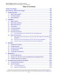
Network Force/Torque Sensor System
Net F/T Manual - ATI Industrial Automation
Net F/T Manual - ATI Industrial Automation

Create successful ePaper yourself
Turn your PDF publications into a flip-book with our unique Google optimized e-Paper software.
Net F/T Installation and Operation Manual<br />
Document: 9620-05-net ft-11<br />
Tool Transform:<br />
Tool transform offsets are defined here. To keep the transducer’s<br />
point of origin at the factory-defined location these values need to<br />
be all zero. Descriptions of the values and the order in which the<br />
values are applied to the factory-defined point of origin are as<br />
follows:<br />
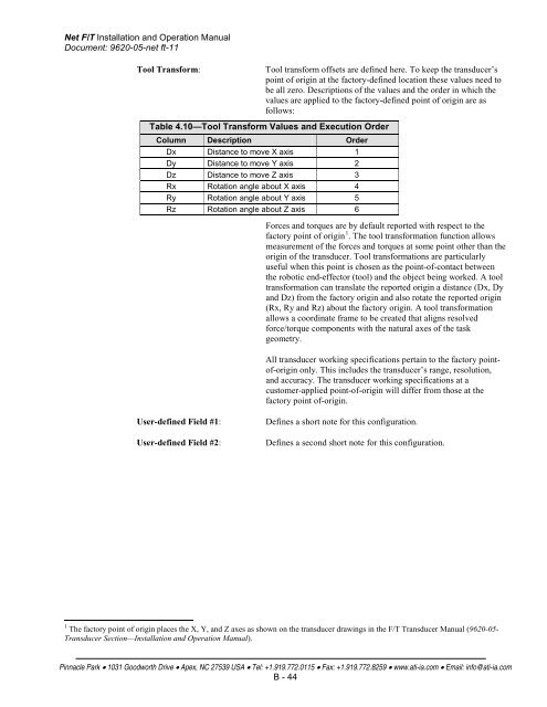
Table 4.10—Tool Transform Values and Execution Order<br />
Column Description Order<br />
Dx Distance to move X axis 1<br />
Dy Distance to move Y axis 2<br />
Dz Distance to move Z axis 3<br />
Rx Rotation angle about X axis 4<br />
Ry Rotation angle about Y axis 5<br />
Rz Rotation angle about Z axis 6<br />
<strong>Force</strong>s and torques are by default reported with respect to the<br />
factory point of origin 1 . The tool transformation function allows<br />
measurement of the forces and torques at some point other than the<br />
origin of the transducer. Tool transformations are particularly<br />
useful when this point is chosen as the point-of-contact between<br />
the robotic end-effector (tool) and the object being worked. A tool<br />
transformation can translate the reported origin a distance (Dx, Dy<br />
and Dz) from the factory origin and also rotate the reported origin<br />
(Rx, Ry and Rz) about the factory origin. A tool transformation<br />
allows a coordinate frame to be created that aligns resolved<br />
force/torque components with the natural axes of the task<br />
geometry.<br />
All transducer working specifications pertain to the factory pointof-origin<br />
only. This includes the transducer’s range, resolution,<br />
and accuracy. The transducer working specifications at a<br />
customer-applied point-of-origin will differ from those at the<br />
factory point of-origin.<br />
User-defined Field #1:<br />
User-defined Field #2:<br />
Defines a short note for this configuration.<br />
Defines a second short note for this configuration.<br />
1 The factory point of origin places the X, Y, and Z axes as shown on the transducer drawings in the F/T Transducer Manual (9620-05-<br />
Transducer Section—Installation and Operation Manual).<br />
Pinnacle Park • 1031 Goodworth Drive • Apex, NC 27539 USA • Tel: +1.919.772.0115 • Fax: +1.919.772.8259 • www.ati-ia.com • Email: info@ati-ia.com<br />
B - 44