Network Force/Torque Sensor System
Net F/T Manual - ATI Industrial Automation
Net F/T Manual - ATI Industrial Automation

Create successful ePaper yourself
Turn your PDF publications into a flip-book with our unique Google optimized e-Paper software.
Net F/T Installation and Operation Manual<br />
Document: 9620-05-net ft-11<br />
19.3.2.2 CAN Interface<br />
19.3.3 Mating Connectors<br />
The CAN interface supports 125 Kbps, 250 Kbps, and 500 Kbps (see Section<br />
3.10.3—Baud Rate). A switchable termination resistor is available (see Section<br />
3.10.1—Termination Resistor).<br />
Table 19.3—Mechanical Specifications of Mating Connectors<br />
Connector Mating Type Recommended <strong>Torque</strong> Maximum <strong>Torque</strong><br />
Ethernet M12 D-Coded, 4-Pin, male 0.8 Nm to 1.0 Nm 3.0 Nm<br />
Threshold Relay M8 3-Pin, female 0.5 Nm to 0.6 Nm 1.0 Nm<br />
Pwr/CAN M12 5-Pin, female 0.8 Nm to 1.0 Nm 3.0 Nm<br />
NETB Transducer M12 5-Pin, male 0.8 Nm to 1.0 Nm 3.0 Nm<br />
NETBA Transducer Circular, female 0.7 Nm<br />
19.3.4 Standard Threshold Relay<br />
The standard threshold relay contacts (NC, NO, or COM) are protected against overload by a<br />
resettable fuse. The relay will turn on within 6ms.<br />
Table 19.4—Standard Threshold Relay<br />
Specifications<br />
Maximum Rating Maximum Load<br />
Current 50mA 10µA<br />
Voltage 42VDC, 30VAC 10mVDC<br />
19.3.5 Solid-State Threshold Relay<br />
The optional solid state threshold relay contacts (SSR+ and SSR-) are protected against reverse<br />
voltage by a zener diode. The relay will turn on within 500µs.<br />
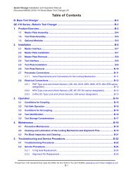
Table 19.5—Solid-State Relay<br />
Specifications<br />
Maximum Load<br />
Current<br />
Voltage<br />
35mA<br />
30VDC<br />
Figure 19.3—Solid-State Relay Voltage Drop vs. Current<br />
Pinnacle Park • 1031 Goodworth Drive • Apex, NC 27539 USA • Tel: +1.919.772.0115 • Fax: +1.919.772.8259 • www.ati-ia.com • Email: info@ati-ia.com<br />
B - 107