Network Force/Torque Sensor System
Net F/T Manual - ATI Industrial Automation
Net F/T Manual - ATI Industrial Automation

Create successful ePaper yourself
Turn your PDF publications into a flip-book with our unique Google optimized e-Paper software.
Net F/T Installation and Operation Manual<br />
Document: 9620-05-net ft-11<br />
4.6.1.2 Fieldbus Net Box and Optional Solid State Threshold Relay<br />
The solid-state relay is standard on the fieldbus Net Box.<br />
The optional solid-state threshold relay has a quicker activation time than the<br />
standard threshold relay and no moving parts to wear out.<br />
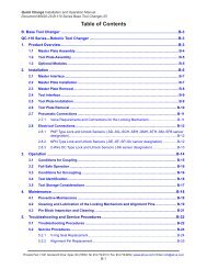
Figure 4.10—Optional Solid State Relay Connector Pin Assignments (male-pin side view)<br />
Figure 4.11—Solid-State Relay Equivalent Output Circuit<br />
3<br />
SSR+<br />
Net Box Solid-<br />
State Relay<br />
1<br />
SSR-<br />
4 unused<br />
Table 4.5—Solid-State Relay Connector Pin Descriptions<br />
Pin Name Description<br />
1 SSR- Solid-State Relay negative connection<br />
3 SSR+ Solid-State Relay positive connection<br />
4 – unused<br />
The solid-state relay can operate at up to 30VDC and at a maximum current of<br />
35mA. The relay can turn on within 500µs of a trigger load. The output is reverse<br />
polarity protected to up to 1A (V r = 1.5V), 47V. The maximum delay from threshold<br />
condition trigger to relay conduction is 500µs.<br />
Pinnacle Park • 1031 Goodworth Drive • Apex, NC 27539 USA • Tel: +1.919.772.0115 • Fax: +1.919.772.8259 • www.ati-ia.com • Email: info@ati-ia.com<br />
B - 39