Network Force/Torque Sensor System
Net F/T Manual - ATI Industrial Automation
Net F/T Manual - ATI Industrial Automation

You also want an ePaper? Increase the reach of your titles
YUMPU automatically turns print PDFs into web optimized ePapers that Google loves.
Net F/T Installation and Operation Manual<br />
Document: 9620-05-net ft-11<br />
Table 3.2—DeviceNet MAC ID Address Switch Settings<br />
123456 123456 123456 123456<br />
0: 000000 16: 000010 32: 000001 48: 000011<br />
1: 100000 17: 100010 33: 100001 49: 100011<br />
2: 010000 18: 010010 34: 010001 50: 010011<br />
3: 110000 19: 110010 35: 110001 51: 110011<br />
4: 001000 20: 001010 36: 001001 52: 001011<br />
5: 101000 21: 101010 37: 101001 53: 101011<br />
6: 011000 22: 011010 38: 011001 54: 011011<br />
7: 111000 23: 111010 39: 111001 55: 111011<br />
8: 000100 24: 000110 40: 000101 56: 000111<br />
9: 100100 25: 100110 41: 100101 57: 100111<br />
10: 010100 26: 010110 42: 010101 58: 010111<br />
11: 110100 27: 110110 43: 110101 59: 110111<br />
12: 001100 28: 001110 44: 001101 60: 001111<br />
13: 101100 29: 101110 45: 101101 61: 101111<br />
14: 011100 30: 011110 46: 011101 62: 011111<br />
15: 111100 31: 111110 47: 111101 63: 111111<br />
Setting DIP switches 1 through 8 to ON will enable both DeviceNet MAC ID and baud rate to<br />
be set by software. If switches 7 or 8 are OFF then the DeviceNet MAC ID will not be set by<br />
software.<br />
3.10.3 Baud Rate<br />
By default, the Net Box ships with a baud rate of 500Kbps. This setting is defined by the DIP<br />
switch settings (see Figure 3.16—DIP Switch Settings for details).<br />
Use Table 3.3—Baud Rate Switch Settings as an aid for finding the switch settings for the baud<br />
rate used by DeviceNet and CAN Bus.<br />
Table 3.3—Baud Rate Switch Settings<br />
Baud Rate 78<br />
125 Kbps: 00<br />
250 Kbps: 10<br />
500 Kbps: 01<br />
Selected by software: 11<br />
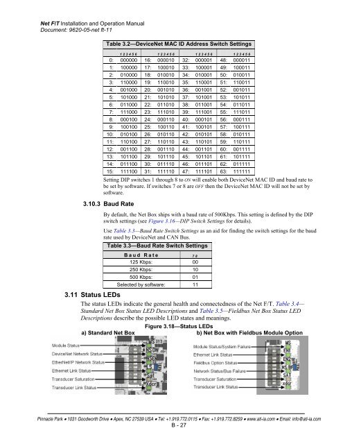
3.11 Status LEDs<br />
The status LEDs indicate the general health and connectedness of the Net F/T. Table 3.4—<br />
Standard Net Box Status LED Descriptions and Table 3.5—Fieldbus Net Box Status LED<br />
Descriptions describe the possible LED states and meanings.<br />
Figure 3.18—Status LEDs<br />
a) Standard Net Box b) Net Box with Fieldbus Module Option<br />
Pinnacle Park • 1031 Goodworth Drive • Apex, NC 27539 USA • Tel: +1.919.772.0115 • Fax: +1.919.772.8259 • www.ati-ia.com • Email: info@ati-ia.com<br />
B - 27