Network Force/Torque Sensor System
Net F/T Manual - ATI Industrial Automation
Net F/T Manual - ATI Industrial Automation

You also want an ePaper? Increase the reach of your titles
YUMPU automatically turns print PDFs into web optimized ePapers that Google loves.
Net F/T Installation and Operation Manual<br />
Document: 9620-05-net ft-11<br />
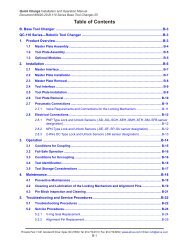
15. CAN Bus Operation<br />
Message<br />
to Net F/T<br />
Request<br />
Long Data<br />
15.1 Overview<br />
The Net F/T supports a basic CAN protocol to allow reading of force/torque data and system status word<br />
over CAN without the need for a DeviceNet scanner.<br />
The CAN Bus base address and Baud Rate settings are configured using the DIP switches. Refer to<br />
Section 3.10—DIP Switches and Termination Resistor for additional information.<br />
To use the Net F/T’s CAN bus protocol, CAN Bus must be selected on the Communications page and<br />
power must be present on the Pwr/CAN connector.<br />
15.2 Protocol Description<br />
A request data message sent to the Net F/T initiates copying of the current set of force and torque data<br />
into an output buffer and the subsequent transmission of the output buffer.<br />
Depending on the request message identifier (REQUEST LONG or REQUEST SHORT), the Net F/T<br />
either sends 32-bit values packed into four messages or 16-bit values packed into two messages.<br />
Values are in little endian format (least-significant byte first). For example, a 16-bit value received as<br />
0x56 0x02 represents 0x0256. Signed numbers use 2’s complement format. The 32-bit value received as<br />
0x0F 0xCF 0xDA 0xDA 0xFD represents 0xFDDACF0F, which is a negative number (because the<br />
highest bit is set). Its decimal value is -35991793.<br />
If a data request message is received during an ongoing transmission, the ongoing transmission will be<br />
terminated and the new request processed.<br />
15.3 Base Address and Communication Format<br />
The CAN Bus base address is set by DIP switches 1 through 6. For more information refer to Section<br />
3.10.2—Node Address and Table 3.1—CAN Bus Base Address Switch Settings. The factory set base<br />
address is 432.<br />
Response<br />
from Net<br />
F/T<br />
Fx and Tx<br />
data<br />
Fy and Ty<br />
data<br />
Fz and Tz<br />
data<br />
Status and<br />
sample<br />
number<br />
CAN<br />
Identifier<br />
Base<br />
Address<br />
Base<br />
Address<br />
+1<br />
Base<br />
Address<br />
+2<br />
Base<br />
Address<br />
+3<br />
Base<br />
Address<br />
+4<br />
Table 15.1—Request Long Data<br />
Data<br />
length in 1 st –4 th data bytes 5 th –8 th data bytes Comment<br />
bytes<br />
1 0x01 (BYTE) N/A Sends a copy of force and torque<br />
data in long format (an ongoing<br />
transmission will be terminated)<br />
8 Fx value (DINT) Tx value (DINT) X-axis force and torque values in<br />
long format<br />
8 Fy value (DINT) Ty value (DINT) Y-axis force and torque values in<br />
long format.<br />
8 Fz value (DINT) Tz value (DINT) Z-axis force and torque values in<br />
long format.<br />
8 system status<br />
(DINT)<br />
sample number<br />
(DINT)<br />
<strong>System</strong> status word and sample<br />
number in long format.<br />
Pinnacle Park • 1031 Goodworth Drive • Apex, NC 27539 USA • Tel: +1.919.772.0115 • Fax: +1.919.772.8259 • www.ati-ia.com • Email: info@ati-ia.com<br />
B - 89