Please click for content. - Orhan Holding
Please click for content. - Orhan Holding
Please click for content. - Orhan Holding

You also want an ePaper? Increase the reach of your titles
YUMPU automatically turns print PDFs into web optimized ePapers that Google loves.
22<br />
Spin welding is a friction welding technique used on<br />
thermoplastic materials, in which the parts to be welded<br />
are heated by friction.<br />
The process of spin welding uses heat generated by<br />
rotational friction at the joint line. The heat generated<br />
during the rotational contact melts the plastic in the<br />
heat⤓affected zone <strong>for</strong>ming a weld upon cooling.<br />
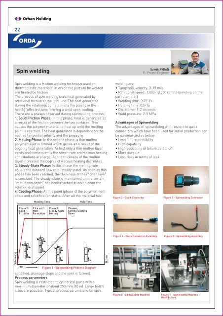
There are 4 phases observed during spinwelding process:<br />
1. Solid Friction Phase: In this phase, heat is generated as<br />
a result of the friction between the two surfaces. This<br />
causes the polymer material to heat up until the melting<br />
point is reached. The heat generated is dependent on the<br />
applied tangential velocity and the pressure.<br />
2. Melting Phase: In the second phase, a thin molten<br />
polymer layer is <strong>for</strong>med which grows as a result of the<br />
ongoing heat generation. At first only a thin molten layer<br />
exists and consequently the shear-rate and viscous heating<br />
contributions are large. As the thickness of the molten<br />
layer increases the degree of viscous heating decreases.<br />
3. Steady-State Phase: In this phase the melting rate<br />
equals the outward flow rate (steady state). As soon as this<br />
phase has been reached, the thickness of the molten layer<br />
is constant. The steady-state is maintained until a certain<br />
"melt down depth" has been reached at which point the<br />
rotation is stopped.<br />
4. Cooling Phase: At this point (phase 4) the polymer melt<br />
cools and solidification starts. After all the material has<br />
Distance<br />
Spin welding<br />
Phase1:<br />
Solid<br />
Friction<br />
Time<br />
Welding Time Hold Time<br />
Phase2:<br />
Melt<br />
Formation<br />
Phase3:<br />
Steady-State<br />
Melting<br />
Phase4:<br />
Setting/Cooling<br />
Down<br />
Figure 1 - Spinwelding Process Diagram<br />
solidified, drainage stops and the joint is <strong>for</strong>med.<br />
Process parameters<br />
Spin welding is restricted to cylindrical parts with a<br />
maximum diameter of about 250 mm (10 in). Large batch<br />
sizes are possible. Typical process parameters <strong>for</strong> spin<br />
Semih AVDAN<br />
FL Project Engineer<br />
welding are:<br />
• Tangential velocity: 3-15 m/s<br />
• Rotational speed: 1,000-18,000 rpm (depending on the<br />
part diameter)<br />
• Welding time: 0.25-1s<br />
• <strong>Holding</strong> time: 0.5-1s<br />
• Cycle time: 1-2 seconds<br />
• Weld pressure: 2-5 MPa<br />
Advantages of Spinwelding<br />
The advantages of spinwelding with respect to quick<br />
connectors which have been used <strong>for</strong> serial production can<br />
be summarized as below:<br />
• Less failure possibility<br />
• High capability<br />
• High possibility of failure detection<br />
• More durable<br />
• Less risky in terms of leak<br />
Figure 2 - Quick Connector Figure 3 - Spinwelding Connector<br />
Figure 4 - Quick Connector Assembly<br />
Figure 5 - Spinwelding Assembly<br />
Figure 6 - Spinwelding Machine Figure 7 - Spinwelding Machine -<br />
Head & Jaws