blind rivets rivet handbook - Ajax Fasteners
blind rivets rivet handbook - Ajax Fasteners
blind rivets rivet handbook - Ajax Fasteners

Create successful ePaper yourself
Turn your PDF publications into a flip-book with our unique Google optimized e-Paper software.
RIVET HANDBOOK
Introduction<br />
PAGE 2<br />
BLIND RIVETS<br />
5a Rivet Fastening Explanation of “<strong>blind</strong>” side fastening<br />
Concepts Installation<br />
Grip Range<br />
Break Loads<br />
Galvanic Corrosion<br />
Removal of Blind Rivets<br />
Standards<br />
5b Rivets Material types<br />
Sizes and codes<br />
Mechanical properties<br />
Head types<br />
Special types<br />
5c Rivet Tools Hand tools<br />
Pneumatic tools<br />
RIVET<br />
HANDBOOK
RIVET<br />
HANDBOOK<br />
Introduction<br />
BLIND RIVETS<br />
5a Rivet Fastening Concepts<br />
• Although bolting is the most common from of fastening in the world, it is restricted in<br />
usage because of the need to screw a nut on the end. There are many applications where<br />
the back of the job cannot be accesses, such as fastening to tubing or walls.<br />
• In these cases, the most common solution is to use Blind Rivets to fasten the job. Blind<br />
<strong><strong>rivet</strong>s</strong> are termed so because there is no need for access to the rear or ‘<strong>blind</strong>’ side of the<br />
joint.<br />
• The use of <strong><strong>rivet</strong>s</strong> in fastening most applications has been proven to be superior and<br />
extremely cost effective when compared with other methods of fastening. Welding,<br />
sheet metal screws, bolts and nuts and solid <strong><strong>rivet</strong>s</strong> all require extensive labour. There<br />
are three main reasons why <strong>blind</strong> <strong><strong>rivet</strong>s</strong> are used.<br />
1. Low Installed cost.<br />
Up to 15 <strong><strong>rivet</strong>s</strong> per minute can be installed without any specialised labour. The<br />
unit cost is also much lower than other types of fastener.<br />
2. Versatility<br />
Blind <strong><strong>rivet</strong>s</strong> are available in many types, sizes and materials to meet the<br />
requirements of the most demanding applications.<br />
3. Reliability<br />
Materials are permanently clamped and provided the correct <strong>rivet</strong> is used can<br />
withstand severe vibration and environmental conditions.<br />
• However, <strong>blind</strong> <strong><strong>rivet</strong>s</strong> are limited in their individual strength and should only be used<br />
when fastening relatively light gauge materials.<br />
PAGE 3
PAGE 4<br />
BLIND RIVETS<br />
5A Rivet Fastening Concepts<br />
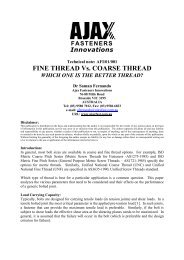
The Installation Process of Blind Rivets<br />
• Blind <strong><strong>rivet</strong>s</strong> are a two-part fastener consisting<br />
of a shell and a headed stem (mandrel)<br />
assembled so the shell can be placed into the<br />
work to be fastened.<br />
• The <strong>rivet</strong> is ‘set’ by drawing the stem through<br />
the shell, which causes the shell to deform and<br />
clamp the material securely.<br />
• After the desired clamping force is achieved,<br />
the stem breaks off and is discarded.<br />
• A small portion of the stem remains trapped in<br />
the bottom of the shell to ensure the clamping<br />
force is retained in the joint.<br />
RIVET<br />
HANDBOOK<br />
• Withdrawing the stem is done with special tools operated by hand, pneumatics or<br />
electricity. Figure 5a-1 shows the stages of application.<br />
Break Load<br />
• The load required to break off the stem is governed by the amount of shell deformation<br />
required and a groove cut to a specific diameter just back from the end. The break load<br />
is designed to prevent too much force being developed which may damage the material<br />
being fastened. Too little clamp force may fail to secure the joint.<br />
• Similar to a bolted joint, a <strong>blind</strong> <strong>rivet</strong> develops a clamping force to secure the joint<br />
members. It is crucial that the mandrel not break at a load lower than the clamping<br />
force. If this occurs. The integrity of the joint may be compromised.<br />
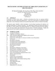
Grip Range<br />
Figure 5a-1. The <strong>rivet</strong> is set by drawing the<br />
stem through the shell.<br />
• Blind <strong><strong>rivet</strong>s</strong> are designed to clamp together<br />
specific thicknesses of material. The amount of<br />
deformation in the shell during setting depends<br />
upon this grip range (figure 5a-2)<br />
• If the grip range is less than it should be (the <strong>rivet</strong><br />
is too long), excessive material will be left on the<br />
<strong>blind</strong> side and more pulls will be required to<br />
Figure 5a-2. Grip Range<br />
break-off the mandrel.<br />
• If the grip range is too large (<strong>rivet</strong> is too short), insufficient material may be left on the<br />
<strong>blind</strong> side to secure the joint.
RIVET<br />
HANDBOOK<br />
Galvanic Corrosion<br />
BLIND RIVETS<br />
5a Rivet Fastening Concepts<br />
• When dissimilar metals come into contact in the presence of an electrolyte, a galvanic<br />
action occurs which corrodes one metal at a faster rate and the other more slowly.<br />
• The rate of corrosion depends upon a) the difference in electrical potential, b) the<br />
conductivity of the electrolyte and c) the relative sizes of the contacting areas.<br />
• Blind <strong><strong>rivet</strong>s</strong> are regularly used with dissimilar metals such as aluminium, stainless steel,<br />
mild steel, zinc-coated steel and copper. In applications high in moisture content – such<br />
as air conditioners and marine environments – particular care needs to be taken to<br />
minimise the effect of galvanic corrosion.<br />
• The following table illustrates which metals should and should not be used together.<br />
Rivet Shell<br />
Material<br />
Aluminium<br />
Al/Zn Coated<br />
Steel<br />
Metal Joined<br />
Zinc Coated<br />
Steel<br />
Stainless<br />
Steel<br />
Copper Brass<br />
Aluminium YES YES ? NO NO NO<br />
Steel Z/P NO YES YES NO NO NO<br />
Nickle<br />
Copper<br />
Stainless<br />
Steel<br />
NO NO NO YES YES YES<br />
? ? ? YES YES YES<br />
Copper NO NO NO YES YES YES<br />
YES<br />
NO<br />
?<br />
o Compatible<br />
o Incompatible. Must not be in contact with each other.<br />
o Compatible in rural and mild environments. Some corrosion may occur in<br />
marine or industrial environments. Painting both metals could reduce the<br />
reaction.<br />
Avoiding Galvanic Corrosion<br />
• When galvanic corrosion becomes a threat to the serviceability of the joint, the<br />
following suggestions may be worth considering.<br />
1. Avoid dissimilar metals by careful selection of rive shell material<br />
2. Build a barrier between the materials such as paint, plastic washers or gaskets.<br />
3. Make provision for drainage to allow water or other electrolyte material to escape.<br />
4. Consider the use of anodized <strong><strong>rivet</strong>s</strong>.<br />
PAGE 5
Removal of Blind Rivets<br />
PAGE 6<br />
BLIND RIVETS<br />
5a Rivet Fastening Concepts<br />
RIVET<br />
HANDBOOK<br />
• If circumstances arise that requires a <strong>blind</strong> <strong>rivet</strong> to be removed, it is recommended that<br />
the following steps be undertaken carefully or damage to the clamped material may<br />
result.<br />
1. Ensure the stem is well below the <strong>rivet</strong> head. If it appears the be flush, drive it<br />
below the head with a punch.<br />
2. Select a drill bit with the same diameter as the recommended hole size for the<br />
<strong>rivet</strong>, and drill through the head until enough material is removed to separate the<br />
head from the shell.<br />
3. Punch the remainder of the shell clear of the clamped material.<br />
Standards<br />
Figure 5a-3. Removal process for <strong>blind</strong> <strong><strong>rivet</strong>s</strong><br />
• There are no Australian nor International standard covering the manufacture and supply<br />
of <strong>blind</strong> <strong><strong>rivet</strong>s</strong>.<br />
• The most recognised standard is IFI 114 – Break Mandrel Rivets from the Industrial<br />
<strong>Fasteners</strong> Institute in the USA. Most suppliers of quality <strong>blind</strong> <strong><strong>rivet</strong>s</strong> use this<br />
specification with a few variations.<br />
• <strong>Ajax</strong> <strong>blind</strong> <strong><strong>rivet</strong>s</strong> are manufactured at our own plant in Singapore and generally adhere<br />
to IFI 114. The most notable exception is the combination of shell / stem materials<br />
which can vary depending upon the aluminium alloy used.<br />
• Three major tests are used to ensure that <strong><strong>rivet</strong>s</strong> comply with the requirements of IFI<br />
114, shear strength, tensile strength and mandrel break load.<br />
• Other tests such as <strong>blind</strong> head formation (usually in conjunction with break load test)<br />
and mandrel retention may be performed as required.
RIVET<br />
HANDBOOK<br />
Shell and Stem Materials<br />
BLIND RIVETS<br />
5b Types of Blind Rivets<br />
• Blind <strong><strong>rivet</strong>s</strong> owe their popularity to ease of installation and versatility. The thousands of<br />
applications that use <strong><strong>rivet</strong>s</strong> created a demand for <strong><strong>rivet</strong>s</strong> made from various types of<br />
material.<br />
• Usually, the governing factors in material selection are strength, corrosion resistance<br />
and the material to be fastened.<br />
• As a general rule, the shell material should be the same as the material under the head,<br />
ie, if aluminium is fastened to steel, use steel <strong><strong>rivet</strong>s</strong>.<br />
Shell Materials<br />
Aluminiun (A)<br />
Lightweight yet strong. Good corrosion resistance.<br />
Steel (S)<br />
Stronger than aluminium with a ‘flash’ coating of zinc.<br />
Stainless Steel (St)<br />
Good strength and excellent corrosion resistance.<br />
Nickel – Copper (M)<br />
Excellent corrosion resistance and conductivity. The strongest <strong>blind</strong> <strong>rivet</strong> material.<br />
Copper ( C)<br />
Relatively soft. Excellent corrosion resistance and conductivity.<br />
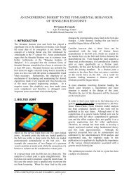
• Figure 5b-1 contrasts the tensile strength of the various shell materials.<br />
Tensile Strength (kN)<br />
3500<br />
3000<br />
2500<br />
2000<br />
1500<br />
1000<br />
500<br />
0<br />
Aluminium Steel Stainless Ni Cu<br />
Shell Material<br />
Figure 5b-1. Relative strengths <strong>blind</strong> <strong>rivet</strong> shells<br />
PAGE 7
Stem Materials<br />
PAGE 8<br />
BLIND RIVETS<br />
5b Types of Blind Rivets<br />
RIVET<br />
HANDBOOK<br />
• Because the greater portion of the stem is discarded after setting, the stem material is<br />
not as crucial, save that it must be ate least the equivalent strength of the shell material.<br />
If not, it will be unable to deform the end of the shell.<br />
• Steel is the most common, although stainless and aluminium stems are available in<br />
some <strong><strong>rivet</strong>s</strong>.<br />
• Part of the stem remains in the shell after setting. In the case of steel, this part may rust,<br />
an undesirable attribute in many circumstances. In these cases, stainless and aluminium<br />
stems may be specified.<br />
Sizes and Codes<br />
• Contrary to popular belief of many ‘expert’ <strong>rivet</strong> users, a <strong>blind</strong> <strong>rivet</strong> will set in one<br />
application of the tool – provided the correct <strong>rivet</strong> is used for that particular job. To<br />
assist with sorting through the many varied types of <strong>blind</strong> <strong><strong>rivet</strong>s</strong>, codes are used to<br />
ensure the best part can be used for the specific application.<br />
• Marketers and manufacturers of <strong><strong>rivet</strong>s</strong> usually assign their own coding systems, <strong>Ajax</strong><br />
use an American system, which has become the industry’s most recognised code. It is<br />
constructed in three parts.<br />
Head Type<br />
73 AS 43<br />
1. Head Type 2. Material Type 3. Rivet Size<br />
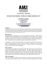
• There are three basic types of head found on <strong>blind</strong> <strong><strong>rivet</strong>s</strong>. The most common is the truss<br />
head which is designated as “73”. Truss heads protrude above the face of the job and<br />
have a “footprint” to share the load and give an impeccable ‘finished’ look.<br />
• The second type is the countersunk variety and is referred to by the code “72”. Type 72<br />
<strong><strong>rivet</strong>s</strong> require the material to be countersunk before the <strong>rivet</strong> is set. This ensures no part<br />
of the fasteners protrudes from the face of the material.<br />
• In situations where the material to be clamped is very brittle or soft, a <strong>rivet</strong> with a large<br />
flanged head is sued. These <strong><strong>rivet</strong>s</strong> are called 73 ASL <strong><strong>rivet</strong>s</strong>. The ASL provides a larger<br />
footprint than the standard 73 (truss) head, which shares the clamping, force over a<br />
wider area on the face of the material.<br />
• Figure 5b-2 illustrates the difference in the three basic head types.
RIVET<br />
HANDBOOK<br />
Shell and Stem Materials<br />
BLIND RIVETS<br />
5b Types of Blind Rivets<br />
Figure 5b-2. Blind <strong><strong>rivet</strong>s</strong> have three basic head styles.<br />
• As indicated in an earlier section, there are various different types of materials available<br />
for both the shell and the stem.<br />
• The second part of the code – consisting of two letters – is used to identify these<br />
materials. The first letter is for the shell material, the second letter is for the stem<br />
material.<br />
• Each material is abbreviated as follows.<br />
Aluminium A<br />
Steel S<br />
Nickel Copper M<br />
Copper C<br />
Stainless Steel ST<br />
• The various combinations are therefore specified thus.<br />
Shell Material Stem Material Code<br />
Aluminium Steel AS<br />
Steel Steel SS<br />
Stainless Steel Steel STS<br />
Stainless Steel Stainless Steel STST<br />
Nickel Copper Steel MS<br />
Copper Steel CS<br />
Aluminium Aluminium AA<br />
PAGE 9
PAGE 10<br />
BLIND RIVETS<br />
5b Types of Blind Rivets<br />
RIVET<br />
HANDBOOK<br />
In the case of special types of <strong>rivet</strong>, the material code may be combined with another<br />
features, eg. 73 ASMG is a truss head Aluminium Steel Multi-Grip. There will be more on<br />
special <strong><strong>rivet</strong>s</strong> in later sections.<br />
Size<br />
• The third section of the code designates the size. The coding system can be rather<br />
complicated until clearly understood and even after then it is best to refer to the data<br />
sheets.<br />
• Rivets are measured under the old imperial system although it is common for metric<br />
specifications to be given. For this reason, conversions are given on the data sheets. The<br />
size code – consisting of two or more numbers – is also in two parts. The first part gives<br />
the diameter of the shell and the second part gives the thickness of material the <strong>rivet</strong> is<br />
designed to clamp (Grip Range).<br />
Shell Diameter<br />
The second figure is not the length of the <strong>rivet</strong> shell<br />
• Using this coding system, the shell diameter is always specified in 1/32nds of an inch,<br />
ie. A No 3. Rivet is 3/32”. The various shell diameters are specified thus:<br />
Shell Code Diameter<br />
3 3/32”<br />
4 4/32” (1/8”)<br />
5 5/32”<br />
6 6/32” (3/16”)<br />
8 8/32” (1/4”)<br />
• Again, metric is often specified so it is best to check the data sheets for the correct<br />
conversion.<br />
Grip Range<br />
• Because part of the shell is collapsed during setting, the most accurate way to get the<br />
correct <strong>rivet</strong> is to specify the thickness of the material to be <strong>rivet</strong>ed. The total thickness<br />
of the material is referred to as the Grip Range.<br />
• Again, the imperial system is used. This time, the grip range is specified in 1/16ths of<br />
an inch. To select the correct <strong>rivet</strong>, it is necessary to measure the thickness to be <strong>rivet</strong>ed<br />
and either convert to 1/16ths or refer to the data sheets.
RIVET<br />
HANDBOOK<br />
Specifying By Code<br />
BLIND RIVETS<br />
5b Types of Blind Rivets<br />
• By now, the <strong>rivet</strong> code at the beginning of this section should make sense. Let’s have a<br />
look at exactly what it is specifying.<br />
73 AS 43<br />
73 = Truss Head<br />
A = Aluminium Shell<br />
S = Steel Stem<br />
4 = 4/32” Shell Diameter<br />
3 = 3/16” Grip Range<br />
• Using the correct <strong>rivet</strong> is vital to secure the joint properly. Whereas the user has a<br />
choice of shell diameter and material, the grip range is dictated by the job itself. Failure<br />
to use the correct <strong>rivet</strong> can cause the joint to collapse.<br />
Special Types of Blind Rivet<br />
• Since the principle behind <strong>blind</strong> <strong><strong>rivet</strong>s</strong> was conceived, many variations have been<br />
developed to satisfy the growing number of applications taking advantage of the<br />
simplicity offered. The following <strong>blind</strong> <strong><strong>rivet</strong>s</strong> are all stocked by <strong>Ajax</strong> <strong>Fasteners</strong> or are<br />
available from various sources.<br />
ASMG – “Multi-Grip” Rivets<br />
• “Multi-Grip” <strong><strong>rivet</strong>s</strong> serve two purposes.<br />
4. To provide a secure joint across varying grip ranges.<br />
5. To effectively seal the shell after setting.<br />
• Before deforming the bottom of the shell, the ASMG collapses on the sides first. When<br />
a tight fit is achieved, only then does the bottom of the shell deform to provide the<br />
necessary claming force.<br />
• They are used in storm water downpipes, guttering and air conditioning ducts as well as<br />
a myriad of general engineering practices.<br />
PAGE 11
ASL – Large Flanged Rivets<br />
PAGE 12<br />
BLIND RIVETS<br />
5b Types of Blind Rivets<br />
RIVET<br />
HANDBOOK<br />
• The large head diameter on the ASL is ideal for soft materials. The clamping force is<br />
spread over a wider area, which prevents excessive damage on the face of the job.<br />
ASG –Grooved Rivets<br />
• Angular grooves around the <strong>rivet</strong> shell provide excellent holding power when set in less<br />
stiff materials such as wood and plastics.<br />
TA – Aluminium Sealed Rivets<br />
• The base of a TA <strong>rivet</strong> is sealed and therefore waterproof. The mandrel is attached to<br />
the inside of the shell ensuring no gaps for water or air to pass through. Commonly used<br />
in water tanks, roofing and aluminium windows.<br />
ASP – Aluminium Peel Rivets<br />
• Peel <strong><strong>rivet</strong>s</strong> are extremely versatile and are necessary<br />
for good cohesion of soft materials without fracture<br />
or distortion. The ridges under the head of the stem<br />
cause the shell to peel back in four different<br />
directions giving a strong reliable fix.<br />
• They are particularly useful for uneven surfaces or<br />
where oversize holes remain after repairs.<br />
Upholstery, rubber and fibreglass are easily fastened<br />
with peel <strong><strong>rivet</strong>s</strong>.<br />
EasyFIXX<br />
Figure 5b-5. The ‘peeling’ action of the shell<br />
provides a strong, reliable fix in softer materials.<br />
• Easyfixx <strong><strong>rivet</strong>s</strong> comprise a 5050/5052 Grade head with a zinc plated steel stem<br />
• What makes them different from the ASP <strong>rivet</strong> is that the 5050/5052 grade aluminium<br />
is softer than the 5056 Grade use on the ASP. This means that it is more forgiving when<br />
<strong>rivet</strong>ing soft or thin materials.<br />
• A shorter shell length also helps reduce the amount of tension on the material to be<br />
<strong>rivet</strong>ed.
RIVET<br />
HANDBOOK<br />
Rivet Tools<br />
BLIND RIVETS<br />
5c Rivet Setting Tools<br />
• Selecting the correct <strong>rivet</strong> setting tool can be as important as selecting the correct <strong>rivet</strong>.<br />
Using a pneumatic tool to set ten 73 AS 42’s can only be considered overkill, but would<br />
be ideal for setting 1,000 per day! The cost savings in labour alone would justify the<br />
expense, not to mention the Workcover claims!<br />
• Many different types of tools are available to suit just about any situation imaginable.<br />
For reasons listed above, pneumatic tools are the preferred option for production lines<br />
and manufacturers. Often, they are used in a fixed work station which allows jobs to be<br />
set faster with less effort.<br />
• Hand tools are used by the handyman who sets only a few <strong><strong>rivet</strong>s</strong>, and in situations<br />
where compressed air is not available for the pneumatic tool.<br />
• Electric tools are also available although their popularity is restricted by a slow setting<br />
time.<br />
Hand Tools<br />
• There are a number of different hand <strong>rivet</strong>ers on<br />
the market, all designed to suit the users budget<br />
and usage requirements.<br />
• The basic <strong>rivet</strong>ers all come with a variety of nibs<br />
to accommodate different stem thicknesses.<br />
• Riveters can also have longer handles, which<br />
provide extra leverage, making larger and stronger<br />
<strong><strong>rivet</strong>s</strong> easier to set.<br />
• And there are even hand <strong>rivet</strong>ers designed to fit<br />
into difficult to get to and confined spaces, such<br />
as the T110 ‘lazy tong’, where there are no<br />
levers and the setting force is generated<br />
courtesy of the leverage provided by the<br />
concertina body. The pushing action also<br />
allows the operator to put their weight behind the tool.<br />
PAGE 13
Pneumatic Rivet Tools<br />
PAGE 14<br />
BLIND RIVETS<br />
5c Rivet Setting Tools<br />
RIVET<br />
HANDBOOK<br />
• Hand tools may be unsuitable for production lines where large quantities of <strong><strong>rivet</strong>s</strong> are<br />
set, or when the shell material is relatively hard, such as stainless steel and nickelcopper.<br />
For these applications, pneumatic tools are a better option.<br />
• The tools use air pressure to apply a traction force to the <strong>rivet</strong> stem during setting. This<br />
relieves stress on the operator and reduces the chances of fatigue and carpel tunnel<br />
syndrome.<br />
• Built-in features such as silencers, mechanical shock reducers and weight distribution<br />
mean that the modern air <strong>rivet</strong>ers are more comfortable to us, which increases<br />
productivity and tool performance.<br />
Operation<br />
1. The <strong>rivet</strong> stem is placed in the nosepiece in a<br />
similar fashion to hand tools.<br />
2. Pressure on the trigger mechanism causes air<br />
to withdraw from the jaw case, which firmly<br />
grips the stem.<br />
3. After setting, the spent stem remains in the<br />
head of the <strong>rivet</strong>er. A gentle tilt backwards<br />
slides the stem into a collector at the rear of<br />
the tool. Vacuum units are available for<br />
some tools, which eliminates the last<br />
operation.
For more information on this product range<br />
or other products in the <strong>Ajax</strong> <strong>Fasteners</strong><br />
range, please call<br />
1800 501 800<br />
RIVET HANDBOOK<br />
SELF DRILLING SCREW<br />
HANDBOOK<br />
82-88 MILLS ROAD<br />
BRAESIDE, VIC 3195 AUSTRALIA<br />
NAIL HANDBOOK<br />
NUT & BOLT HANDBOOK