

(2) AMPLIFICADOR 2R COMPLETO LYNX-v3-0-QAG
LYNX-v3-0-QAG
LYNX-v3-0-QAG

You also want an ePaper? Increase the reach of your titles
YUMPU automatically turns print PDFs into web optimized ePapers that Google loves.
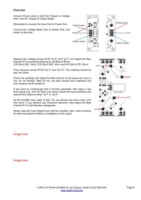
Final test<br />
Connect Power wires to both the “Supply to Voltage<br />
Amp” and the “Supply to Output Stage”.<br />
Remember to connect the Input Gnd to Power Gnd.<br />
Connect the Voltage Meter Gnd to Power Gnd, and<br />
power up the amp.<br />
Measure the Voltage across R128 (“tp E” and “tp F”) and adjust the Bias<br />
trimmer R114 according following to set Bias to 50mA:<br />
If R128=0.2<strong>2R</strong>: 10mV, if R128=0.33R: 16mV and if R128=0.47R: 23mV<br />
Then measure across R129 (“tp G” and “tp H”). The readings should be<br />
app. the same.<br />
Check the readings and adjust the Bias trimmer to the above for every 5<br />
min. for 30 minutes. After 30 min. the Bias should have stabilized and<br />
only measure small variations.<br />
If you have an oscilloscope and a function generator, then apply a low<br />
level signal (e.g. 100 mV/1kHz sine wave) across the Input terminals and<br />
observe the output at either “tp F” or “tp H”.<br />
As the amplifier has a gain of app. 25, you should now see a clear 2.5V<br />
sine wave. If you observe any crossover distortion, then adjust the Bias<br />
trimmer R114 until distortion disappears.<br />
Slowly raise the Input Signal level until the amplifier clips, while checking<br />
for abnormal signal handling or oscillation on the output.<br />
Image here<br />
Image here<br />
<strong>LYNX</strong> <strong>v3</strong>.0 Power Amplifier by Jan Dupont, Audio Circuit Denmark<br />
www.audio-circuit.dk<br />
Page 8