A REVIEW ON HYBRID GOKART
Transportation, both public and private, has become an important part of our day-to-day life. Its usage has increased enormously leading to an increase in consumption of fuels. Global warming at this junction seems to be elevating rapidly. However, due to the increased consumption of fuels and the depleting resources, there will be non-availability of fossil fuels in the coming future. An alternative to this can be use of green vehicles. But, as the source of their energy is in batteries, the best solution out of the both is hybrid vehicle transportation
Transportation, both public and private, has become an important part of our day-to-day life. Its usage has increased
enormously leading to an increase in consumption of fuels. Global warming at this junction seems to be elevating rapidly.
However, due to the increased consumption of fuels and the depleting resources, there will be non-availability of
fossil fuels in the coming future. An alternative to this can be use of green vehicles. But, as the source of their energy is
in batteries, the best solution out of the both is hybrid vehicle transportation

You also want an ePaper? Increase the reach of your titles
YUMPU automatically turns print PDFs into web optimized ePapers that Google loves.
International Journal of Research and Innovation (IJRI)<br />
1401-1402<br />
International Journal of Research and Innovation (IJRI)<br />
Garine Ramakrishna, Vishnu Kumar Budama,<br />
A <strong>REVIEW</strong> <strong>ON</strong> <strong>HYBRID</strong> <strong>GOKART</strong><br />
1 Research Scholar, Department of Mechanical Engineering, Vallurupalli Nageswara Rao Vignana JyothiInstitute of Engineering &<br />
Technology,Bachupally, Nizampet,Hyderabad,T.S., India<br />
2 Assistant Professor, Department of Mechanical Engineering, Vallurupalli Nageswara Rao Vignana JyothiInstitute of Engineering &<br />
Technology,Bachupally, Nizampet,Hyderabad,T.S., India<br />
Abstract<br />
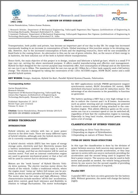
Transportation, both public and private, has become an important part of our day-to-day life. Its usage has increased<br />
enormously leading to an increase in consumption of fuels. Global warming at this junction seems to be elevating rapidly.<br />
However, due to the increased consumption of fuels and the depleting resources, there will be non-availability of<br />
fossil fuels in the coming future. An alternative to this can be use of green vehicles. But, as the source of their energy is<br />
in batteries, the best solution out of the both is hybrid vehicle transportation.<br />
Hence forth, the main objective of this project is to design, analyze and fabricate a hybrid go-kart, which is a small F-9<br />
type race car, serving the above mentioned purpose. It offers easeful manufacturing and effective cost management.<br />
Hybrid Go-Kart designed for the current purpose may tentatively offer, fuel consumption of 25kmpl and on the batteries<br />
we can run it up to 40km. The maximum limit for one run can go till 150km for a 5 liter tank capacity and a full battery<br />
charge. The chassis is designed by taking the constraints of the 125cc ACCESS engine, 850W BLDC motor and a mild<br />
parallel hybrid system.<br />
KEY WORDS: Design, Analysis, Hybrid Go-Kart, Parallel Hybrid System,Chassis, Fabrication.<br />
*Corresponding Author:<br />
Garine Ramakrishna,<br />
Research Scholar,<br />
Department Of Mechanical Engineering, Vallurupalli Nageswara<br />
Rao Vignana JyothiInstitute of Engineering &<br />
Technology,Bachupally, Nizampet,Hyderabad,T.S., India<br />
Published: September 27, 2015<br />
Review Type: peer reviewed<br />
Volume: II, Issue : V<br />
Citation: Garine Ramakrishna, Research Scholar (2015) A<br />
<strong>REVIEW</strong> <strong>ON</strong> <strong>HYBRID</strong> <strong>GOKART</strong><br />
<strong>HYBRID</strong> TECHNOLOGY<br />
INTRODUCTI<strong>ON</strong><br />
Hybrid vehicles are vehicles with two or more power<br />
sources in the drive train. There are many different types<br />
of hybrid vehicles, although only the hybrid electric vehicle<br />
is currently commercially available.<br />
A hybrid electric vehicle (HEV) has two types of energy<br />
storage units, electricity and fuel. Electricity means that<br />
a battery (sometimes assisted by ultra-caps) is used to<br />
store the energy, and that an electromotor will be used as<br />
traction motor. Fuel and an internal combustion engine<br />
are used to generate mechanical power or that a fuel cell<br />
will be used to convert fuel to electrical energy.<br />
Motors are the "work horses" of Hybrid Electric Vehicle<br />
drive systems. The electric traction motor drives the<br />
wheels of the vehicle. Unlike a traditional vehicle, where<br />
the engine must "ramp up" before full torque can be provided,<br />
an electric motor provides full torque at low speeds.<br />
The motor also has low noise and high efficiency. Other<br />
characteristics include excellent "off the line" acceleration,<br />
good drive control, good fault tolerance and flexibility in<br />
relation to voltage fluctuations. The motor technologies<br />
for HEV applications include PMSM (permanent magnet<br />
synchronous motor), BLDC (brushless DC motor), SRM<br />
(switched reluctance motor) and AC induction motor. The<br />
advantage of an electromotor is the possibility to function<br />
as generator.<br />
The battery packing a HEV has a very high voltage in order<br />
to reduce the current and I to R losses. Accessories<br />
such as power steering and air conditioning are powered<br />
by electric motors instead of being attached to the combustion<br />
engine. This allows efficiency gains as the accessories<br />
can run at a constant speed or can be switched off,<br />
regardless of how fast the combustion engine is running.<br />
Especially in long haul trucks, electrical power steering<br />
saves a lot of energy.<br />
CLASSIFICATI<strong>ON</strong> OF <strong>HYBRID</strong> VEHICLES<br />
1.Depending on Drive Train Structure.<br />
2.Depending on degree of Hybridization.<br />
3.Depending on nature of Power Source.<br />
TYPES BY DRIVE TRAIN STRUCTURE<br />
In this type the classification is done by the division of<br />
power between sources; both sources may operate in parallel<br />
to simultaneously provide acceleration, or they may<br />
operate in series with one source exclusively providing the<br />
acceleration and the second being used to augment the<br />
first's power reserve. The sources can also be used in both<br />
series and parallel as needed, the vehicle being primarily<br />
driven by one source but the second capable of providing<br />
direct additional acceleration if required.<br />
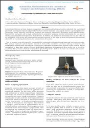
Parallel HEV<br />
A parallel HEV can have an extra generator for the battery<br />
(left). Without generator, the motor will charge the battery<br />
(right).<br />
185
International Journal of Research and Innovation (IJRI)<br />
Operating modes<br />
PARTS OF A GO-KART<br />
In a Go-kart, there are mainly six parts. They are:<br />
• Chassis<br />
• Steering System<br />
• Braking System<br />
• Transmission<br />
1. Engine<br />
2. Motor<br />
• Tires<br />
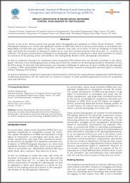
CHASSIS:<br />
The Chassis is an extremely important element of the<br />
kart, as it must provide, the equivalent of suspension to<br />
give good grip at the front. Karts have no suspension, and<br />
are usually no bigger than is needed to mount a seat for<br />
the driver and a small engine. Chassis construction is<br />
normally of a tubular construction, typically GI with different<br />
grades. In this kart, the chassis supports the power<br />
unit, power train, the running system etc.<br />
Advantages of parallel hybrid vehicles:<br />
• Total efficiency is higher during cruising and long-distance<br />
highway driving.<br />
• Large flexibility to switch between electric and IC EN-<br />
GINE power<br />
• Compared to series hybrids, the electromotor can be designed<br />
less powerful than the IC ENGINE, as it is assisting<br />
traction. Only one electrical motor/generator is required.<br />
Weaknesses of parallel hybrid vehicles:<br />
• Rather complicated system.<br />
• The IC ENGINE doesn't operate in a narrow or constant<br />
RPM range, thus efficiency drops at low rotation speed.<br />
•As the IC ENGINE is not decoupled from the wheels, the<br />
battery cannot be charged at standstill.<br />
GO-KART<br />
INTRODUCTI<strong>ON</strong><br />
STEERING SYSTEM<br />
INTRODUCTI<strong>ON</strong><br />
This system provides the directional change in the movement<br />
of an Automobile and maintain in a position as per<br />
the driver's decision without much strain on him.<br />
REQUIREMENTS OF STEERING SYSTEM<br />
• It must keep the wheel at all times in to rolling motion<br />
without rubbing on the road.<br />
• This system should associate to control the speed.<br />
• It must light and stable.<br />
• It should also absorb the road shocks.<br />
There are many motor sports in the world. Bikes, cars,<br />
Formula one are examples of them. In those, drivers are<br />
very professional and accurate. They can drive it very fast.<br />
There are also motor sports which do not need professional<br />
drivers and need no great speed and cost. Go-kart<br />
comes under this criterion. It resembles the formula one<br />
car but it is not faster as F1 and also less expensive. Even<br />
children can also drive it. Go-karts have 4 wheels and a<br />
small engine. They are widely used in racing in US and<br />
also getting popular in India.<br />
ABOUT GO-KARTS<br />
Go-kart is a simple four wheeled, small engine, single<br />
seated racing car used mainly in United States .They were<br />
initially created in the 1950's. Post war period by airmen<br />
as a way to pass spare time. Art Ingles is called the father<br />
of karting. He built the first kart in Southern California<br />
in 1960's. From then, it.s being popular all over America<br />
and also Europe.<br />
BRAKING SYSTEM<br />
The braking system is designed such that the stopping<br />
distance is minimum and the effort to be applied by the<br />
driver on the pedal is minimum. The brakes will work effectively<br />
when the contact area of the brake pads and the<br />
disc plate is maximum which will reduce the stopping distance.<br />
The area of the piston in the master cylinder has<br />
also effect on the braking of the vehicle.<br />
186
International Journal of Research and Innovation (IJRI)<br />
Brake Pedal Force<br />
Pedal Ratio=L2/L1 =300/60 =5.<br />
Fd= Force Applied by Driver = 20Kg = 196 N.<br />
Fbp=Force Output on Brake Pedal Assembly = Fd x L2<br />
L1=196 x 300/ 60 =980 N<br />
The Master Cylinder<br />
D= Bore Diameter of Master Cylinder = 0.393 in = 0.998<br />
cm =9.98 x 10 -3 m.<br />
A mc<br />
=Area of Bore = 7.822 x 10 -5 m 2<br />
P mc<br />
=Pressure on Master Cylinder = Fbp/Amc<br />
=12528765.02 N/m2 = 12528.765 KN/m2<br />
Pressure on Caliper<br />
P cal<br />
=Pressure on Caliper=Pressure on the Master Cylinder.<br />
Torque Required<br />
P cal<br />
=P mc<br />
Mass Moment of Inertia= I = Mk2 = 0.049 Kgm2<br />
Angular Velocity = ώ = V R = 100 Rad/Sec<br />
Angular Displacement = stopping Distance R = 30.9227rad<br />
K.E of Translation on Front Tyre = KEt,f = 1 2<br />
XV r,d XVv<br />
Z = 265155.93 J<br />
K.E of Translation on Rear Tyre = KEt,r = 1 2 XV r,d XVv<br />
z = 39270.906 J<br />
K.E of Rotation on Front Tyre = KEr,r = 1 2IW 2<br />
= 245 J<br />
K.E of Translation on Rear Tyre = KEr,r =1 2IW 2<br />
= 245 J<br />
Net Kinetic Energy on Front Tyre = KEnet,r = 265400.93 J<br />
Net Kinetic Energy on Rear Tyre = KEnet,r = 39515.906 J<br />
Torque on Two Front Tyres = T 2f<br />
= kEnet,f = 8582.72 Nm<br />
Torque on Two Rear Tyres = T 2r<br />
= kEnet,f = 1227.89 Nm<br />
Torque on Two Front Tyre = Tf = T 2f<br />
= 4291.36 Nm<br />
Torque on Each Front Tyre = Tr =T 2r<br />
= 613.94 Nm<br />
SPECIFICATI<strong>ON</strong> OF ENGINE<br />
Type: - 4 stroke, single cylinder, air cooled OHC<br />
Displacement: - 124cm3<br />
Max power:- 6.4kw at 7000 rpm 8.85 bhp at 7000rpm<br />
Max torque:-9.8Nm at 5000 rpm (1.0kg-m at 5000rpm<br />
Starter system: - self &kick<br />
SYSTEMS USED IN GO-KART<br />
MAIN SYSTEMS USED IN GO-KART:<br />
• Fuel system<br />
• Ignition system<br />
• Lubrication system<br />
• Cooling system<br />
FUEL SYSTEM<br />
The purpose of fuel system in SI engines is to store and<br />
supply fuel then to pump this fuel to carburetors. The<br />
fuel supply system also prepares the air-fuel mixture for<br />
combustion in the cylinder and carries the exhaust gas to<br />
the rear of the vehicle. The basic fuel supply system used<br />
in the vehicle consists of the following.<br />
• Fuel tank<br />
• Fuel strainer or Fuel filter<br />
• Air cleaner<br />
• Carburetor<br />
Fuel Tank - It is reservoir of fuel oil for an engine. It is<br />
kept in and elevated position so that the fuel will flow to<br />
the carburetor through the filter by gravity. Our fuel tank<br />
has a capacity of 1 liter and there is also a filter by gravity.<br />
Our fuel tank has a capacity of 1 liter and there is also a<br />
fuel level indicator in it.<br />
Fuel Filter - Dust, particles of dirt or other unwanted<br />
particles might be present in the petrol. This petrol should<br />
be free from these particles. Therefore, the petrol filter is<br />
used.<br />
Air Cleaner - Since the atmospheric air is highly cornices<br />
and contains dust and dirt particles, it is allowed to enter<br />
the engine intake manifold only through an air cleaner.<br />
Carburetor - The mixture of petrol and air burns in the<br />
combustion chamber of the engine. The carburetor is a<br />
device to mix the petrol with air in the proper ratio for<br />
the purpose of combustion. The quantity of petrol and<br />
air can be indifferent ratios. The quantity of petrol can<br />
sometimes be more and sometimes less. The speed of the<br />
engine changes according to the richness of the petrol in<br />
the mixture.<br />
IGNITI<strong>ON</strong> SYSTEM<br />
The ignition system used for small two-stroke engine is<br />
flywheel magneto type. The advantage of this system is<br />
that it is set combined. The flywheel magneto is basically<br />
used only for a single cylinder engine though ones suitable<br />
for multi-cylinder engine have also been developed.<br />
The principles of this type of ignition can be easily understood<br />
with following description.<br />
IGNITI<strong>ON</strong> COIL<br />
The coil consists, in fact, of two coils which may be considered<br />
as separated electrically, although they are both<br />
wound on the same iron core and share a common terminal.<br />
One coil, known as the primary, is fed from the<br />
battery, and the principle of operation depends upon the<br />
fact that, if the supply to this coil is suddenly interrupted,<br />
then the voltage is created or induced in the other coil<br />
known as the secondary.<br />
The voltage in the two coils can be considered for our purpose<br />
to be in the same ratio as the number of turns of wire<br />
on the two coils, so that by providing relatively few turns<br />
on the primary winding and a very large number on the<br />
secondary the necessary, high voltage is obtained.<br />
SPARK PLUG<br />
An essential part of the ignition system is the provision<br />
of electrodes within the engine cylinder, across which the<br />
ignition spark can discharge. It is desirable to arrange<br />
that these electrodes shall be easily accessible and they<br />
are, therefore, mounted on a screwed-in plug.<br />
A sparking plug consist essentially of a steel body which<br />
bears the earthed electrode, an insulator, and a central<br />
rode which forms the other electrode, fed from the distributor.<br />
The lower part of the body is threaded to suit<br />
a screwed bole provided in the engine, the length of the<br />
187
International Journal of Research and Innovation (IJRI)<br />
threaded portion known as the reach and varying with the<br />
plug design. The body of the plug seats on to a soft steel<br />
washer when it is screwed into the engine.<br />
LUBRICATI<strong>ON</strong> SYSTEM<br />
type of analysis is typically used for the designed and optimization<br />
of system for too complex to analyze by hand.<br />
Systemsthat make fir into this category are too complex<br />
due to their geometry, or governing equations.<br />
It is a common known that if two rough surfaces are<br />
rubbed together, there is a resistance to the motion and<br />
heat is generated. In an IC engine those surfaces which<br />
rub together are not tough by normal standards, yet if<br />
they are allowed to run in direct contact get one another,<br />
the temperature more rise to so high a degree that local<br />
melting will occur and the surfaces will slide to seize. It<br />
has been shown than even if the surfaces are super finished,<br />
seizing will occur unless lubrication is provided.<br />
TRANSMISSI<strong>ON</strong><br />
WORKING OF AUTOMATIC TRANSMISSI<strong>ON</strong><br />
This go-kart has no gears and clutches. The transmission<br />
used is automatic and not manual. For this purpose, variable<br />
transmission is continuously used. Pulley and belt<br />
system type CVT is used.<br />
This type of CVT uses pulleys, typically connected by a<br />
metal levered rubber belt. A chain may also be used. A<br />
large pulley connected to a smaller pulley with a belt on<br />
chain will operate in the same manner as a large gear<br />
meshing with a small gear. Typical CVTs have pulleys<br />
formed as pairs of opposing cones. Moving the cones in<br />
and out has the effect of changing the pulley diameter,<br />
since the belt or chain must take a large diameter path<br />
when the conical pulleys halves are close together. This<br />
motion of the cones can be computer controlled and driven<br />
for example, by a servomotor. However in the light weight<br />
VDP transmissions used in automatic motor scooters and<br />
light motor cycles, the change in pulley diameter is accomplished<br />
by a variation, an all mechanical system that<br />
uses weights and springs to change the pulley diameters<br />
as a function of belt speed.<br />
TORQUE AND SPEED AT WHEEL<br />
T at wheel=3.82*3.18=12.17 N-m<br />
N=3000/3.83=783.3 rpm<br />
Velocity= πDN/60= π*0.36*783.3/60= 14.7 m/s<br />
Velocity= 14.7*18/5=53 Km/Hr<br />
DESIGN<br />
CATIA (COMPUTER AIDED THREE DIMENSI<strong>ON</strong>AL IN-<br />
TERACTIVE APPLICATI<strong>ON</strong>) is a multiple form CAD/CAM/<br />
CAE commercial software suite developed by French<br />
company Dassault systems. The software was created in<br />
late 1970s to develop Dassault's Mirage fighter jet, but<br />
was subsequently adapted in aerospace, automotive ship<br />
building, and other industries.<br />
ANALYSIS<br />
INTRODUCTI<strong>ON</strong> TO ANSYS:<br />
ANSYS is general purpose finite element analysis (FEA)<br />
software package. Finite element numerical method of a<br />
deconstructing a complex system into very small pieces<br />
(user designated size) called element. The software implements<br />
equations that governs the behavior of these elements<br />
and solver them all; creating a comprehensive explanation<br />
of how the system acts as a whole. These results<br />
than can be presented in tabulate or graphical forms. This<br />
ANSYS is the standard FEA teaching tool within the engineering<br />
department at many colleges. Ansys is also used<br />
in civil and Electrical engineering, as well as physics and<br />
chemistry department.<br />
ANSYS provide a cost effective way to explore the performance<br />
of the products and processes in a virtual environment.<br />
This type of product development is termed as<br />
virtual Prototyping. With virtual prototyping techniques<br />
users can iterate various scenarios to optimize the product<br />
long before manufacturing is started. This enables a<br />
reduction in level of risk, And in the cost of ineffective<br />
designs. The multifaceted nature of Ansys also provides<br />
a means of ensure that users are able to see the effect of<br />
designs on the whole behavior of the product, be it electromagnetic,<br />
thermal, mechanical etc.<br />
GENERIC STEPS TO SOLVING ANY PROBLEM IN ANSYS:<br />
Like solving any problem analytically, one needs to define<br />
(1) the solution domain, (2) the physical model, (3) boundary<br />
conditions and (4) the physical properties. Then the<br />
problem can be solved and the results can be presented.<br />
In numerical methods, the main difference in an extra<br />
step called mesh generation. This is the step that divides<br />
the complex model in to small elements that become soluble<br />
in an otherwise too complex situation. Below describes<br />
the process in terminology. Slightly more attune too the<br />
software.<br />
BUILD GEOMETRY<br />
Construct a 2 or 3 –D representation of the object to be<br />
modeled and tested using the work plane coordinates system<br />
in ANSYS.<br />
DEFINE MATERIAL PROPERTIES<br />
Now that the part exists, define a library of necessary materials<br />
that composed an object (or project) being modeled.<br />
This includes thermal and mechanical properties.<br />
GENERATE MESH<br />
At this point ANSYS understands the makeup of the part.<br />
Now define how the model system should be broken down<br />
into finite pieces.<br />
APPLY LOADS<br />
Once the system is fully designed, the last task is to burden<br />
the system with constraints, such as physical load-<br />
188
International Journal of Research and Innovation (IJRI)<br />
ings or boundary conditions.<br />
OBTAIN SOLUTI<strong>ON</strong><br />
This is actually a step because ANSYS need to understand<br />
within what state (steady state, transient… etc.)<br />
The problem must be solved.<br />
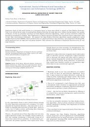
TORSI<strong>ON</strong>AL ANALYSIS<br />
For Torsional analysis, 3G loads are considered.<br />
M = 250 kg<br />
G=250X10 = 2500kg<br />
F = 3G = 3X2500 = 7500<br />
SPECIFIC CAPABILITIES OF ANSYS<br />
STRUCTURAL<br />
Structural analysis is probably the most common application<br />
of the finite element method is as it implies bridges<br />
and buildings, naval, aeronautical and mechanical structure<br />
such as ship halls, air crafts and machines housing<br />
as well as mechanical components such as pistons, machine<br />
parts and tools. Static analysis issued to determine<br />
displacement, stresses etc. under static loading conditions.<br />
ANSYS can compute both linear and non-linear static<br />
analysis. Non linearity can include plasticity, stress stiffening,<br />
large deflection, large strain, hyper elasticity, contact<br />
surface and creep.<br />
Torsional Analysis Total Deformation<br />
CALCULATI<strong>ON</strong>S:<br />
STATIC LOADING (VERTICAL BENDING):<br />
Acceleration due to gravity= 9.81 m/s2<br />
Weight of chassis = 40 kg, Driver = 70 kg, Engine = 35 kg,<br />
Motor = 10 kg,<br />
Battery = 40 kg<br />
Now, total vertical static force including gravitational F=<br />
m x 9.81<br />
'<br />
FABRICATI<strong>ON</strong><br />
MATERIAL<br />
Static Loading Total Deformation<br />
Traditionally, space-frames are constructed from circular<br />
hollow section tube as this was much easier to join.<br />
These circular seamless pipes also allowed easy fabrication<br />
techniques, as all welded joints were flush. Modern<br />
space-frames are now entirely fabricated from round tubular<br />
steel members to provide a torsion ally ridged chassis<br />
frame. This process involves more complicated fabrication<br />
techniques as precision notching is required to<br />
achieve a strong structural join. These joining methods<br />
have been made much easier for hardened steels with the<br />
introduction of high quality tooling. Notching also increases<br />
the amount of weld area increasing the strength,<br />
which can be seen in the Figure.<br />
Front Impact Total Deformation<br />
189
International Journal of Research and Innovation (IJRI)<br />
C<strong>ON</strong>CLUSI<strong>ON</strong><br />
AUTHOR<br />
A hybrid go-kart, smaller version of F-9 type race car, offers<br />
many advantages in both manufacturing and cost.<br />
In addition, it is economical too on the consumption and<br />
on the capacities of batteries. With a concern to the environmental<br />
issues, this vehicle offers suitability to several<br />
transient conditions. Hence, this project focused on the<br />
design, analysis and fabrication of the same.<br />
As per the design guidelines, even considering the worstcase<br />
scenarios, of the boundary and loading conditions<br />
that occur on the model of the car, the factor of safety was<br />
found to be optimal. Based on the analysis report generated,<br />
the chassis too is analyzed by taking the constraints<br />
of the engine. The parameters evaluated from ANSYS software<br />
were found to be acceptable, allowing fabricating the<br />
car. The fabricated model is also shown as part of presentations<br />
with the necessary deformation plots of the chassis<br />
and the car. The results from the run of the car were<br />
in accordance with the design parameters considered in<br />
designing the car.<br />
Garine Ramakrishna<br />
Research Scholar,<br />
Department of Mechanical Engineering,<br />
Vallurupalli Nageswara Rao Vignana Jyothi<br />
Institute of Engineering & Technology,Bachupally,<br />
Nizampet,Hyderabad,T.S., India<br />
REFERENCES<br />
1.“Race Car Vehicle Dynamics”, Milliken, William F., Milliken,<br />
Douglas L., Society of Automotive Engineers, 1997.<br />
2.“Automotive Engineering Fundamentals”, Richard<br />
Stone and Jeffrey K. Ball.<br />
3.“Design, Analysis and Testing of a Formula SAE Car<br />
Chassis”, William B. Riley and Albert R. George.<br />
4.“Electric and Vehicles Design Fundamentals”. Iqbal Husain<br />
5. “Chassis Engineering”, Herb Adams.<br />
6. www.wikipedia.com<br />
7. “How to Make Your Car Handle”, Fred Puhn.<br />
8. “Vehicle Dynamics: Theory and Applications by Reza N.<br />
Jazar.<br />
9. “Engineering Mechanics”, S. Timoshenko, D.H. Young,<br />
and Tata McGraw Hill Publications.<br />
Vishnu Kumar Budama,<br />
Assistant Professor<br />
Department of Mechanical Engineering,<br />
Vallurupalli Nageswara Rao Vignana Jyothi<br />
Institute of Engineering & Technology,Bachupally,<br />
Nizampet,Hyderabad,T.S., India<br />
190