FAILURE ANALYSIS OF IC ENGINE VALVES BY USING FEA
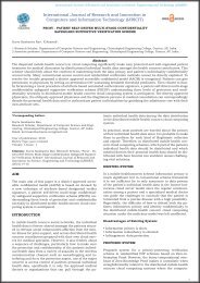
Intake and exhaust valves are very important engine components that are used to control the flow of intake and exhaust gases in internal combustion engines. They are used to seal the working space inside the cylinder against the manifolds; and are opened and closed by means of what is known as the valve train mechanism.. These valves are loaded by spring forces and subjected to thermal loading due to high temperature and pressure inside the cylinder. The present study is forced on different failure modes of internal combustion engine valves. Failures due to fatigue, high temperature effects, and failures due to impact load that depends on load and time. For the study of fatigue life, a combined s-n (max. Stress v/s number of cycles) curve is prepared. Such a curve helps in comparing the fatigue failure for different materials at different high temperatures and may also assist the researchers in developing the valve materials with a prolonged life.
Intake and exhaust valves are very important engine components that are used to control the flow of intake and exhaust
gases in internal combustion engines. They are used to seal the working space inside the cylinder against the manifolds;
and are opened and closed by means of what is known as the valve train mechanism.. These valves are loaded by spring
forces and subjected to thermal loading due to high temperature and pressure inside the cylinder.
The present study is forced on different failure modes of internal combustion engine valves.
Failures due to fatigue, high temperature effects, and failures due to impact load that depends on load and time.
For the study of fatigue life, a combined s-n (max. Stress v/s number of cycles) curve is prepared. Such a curve helps in
comparing the fatigue failure for different materials at different high temperatures and may also assist the researchers
in developing the valve materials with a prolonged life.

You also want an ePaper? Increase the reach of your titles
YUMPU automatically turns print PDFs into web optimized ePapers that Google loves.
International Journal of Research and Innovation (IJRI)<br />
International Journal of Research and Innovation (IJRI)<br />
1401-1402<br />
<strong>FAILURE</strong> <strong>ANALYSIS</strong> <strong>OF</strong> <strong>IC</strong> <strong>ENGINE</strong> <strong>VALVES</strong> <strong>BY</strong> <strong>USING</strong> <strong>FEA</strong><br />
K.Venkata Narayana 1 , K.koteswara Rao 2 ,Y Dhana Shekar 3<br />
1 Research Scholar,Department Of Thermal Engineering, Kits, Peddapuram(M) Tirupathi Village, Divili 533-433,Eg Dt,AP, India.<br />
2 Associate Professor,Department Of Thermal Engineering, Kits, Peddapuram(M) Tirupathi Village, Divili 533-433,Eg Dt,AP, India.<br />
3 Assistant Professor , Department Of Thermal Engineering, Kits, Peddapuram(M) Tirupathi Village, Divili 533-433,Eg Dt,AP, India.<br />
Abstract<br />
Intake and exhaust valves are very important engine components that are used to control the flow of intake and exhaust<br />
gases in internal combustion engines. They are used to seal the working space inside the cylinder against the manifolds;<br />
and are opened and closed by means of what is known as the valve train mechanism.. These valves are loaded by spring<br />
forces and subjected to thermal loading due to high temperature and pressure inside the cylinder.<br />
The present study is forced on different failure modes of internal combustion engine valves.<br />
Failures due to fatigue, high temperature effects, and failures due to impact load that depends on load and time.<br />
For the study of fatigue life, a combined s-n (max. Stress v/s number of cycles) curve is prepared. Such a curve helps in<br />
comparing the fatigue failure for different materials at different high temperatures and may also assist the researchers<br />
in developing the valve materials with a prolonged life.<br />
For achieving above sad goals couple –field, fatigue and transient analysis will be done on valves to determine structural<br />
and thermal behavior in working condition.<br />
Graphs will be generated for the same for easy understanding.<br />
Keywords: Failure, internal combustion engine valves, high temperature, fatigue, wear<br />
*Corresponding Author:<br />
Kancharla Venkata Narayana,<br />
Research Scholar,Department Of Thermal Engineering,<br />
Kits, Peddapuram(M) Tirupathi Village, Divili 533-433,<br />
Eg Dt,AP, India.<br />
Published: January 22, 2015<br />
Review Type: peer reviewed<br />
Volume: II, Issue : I<br />
Citation: Kancharla Venkata Narayana,<strong>FAILURE</strong> <strong>ANALYSIS</strong><br />
<strong>OF</strong> <strong>IC</strong> <strong>ENGINE</strong> <strong>VALVES</strong> <strong>BY</strong> <strong>USING</strong> <strong>FEA</strong><br />
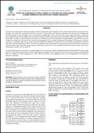
Problem Discription<br />
This project deals with “transient structural, transient<br />
thermal analysis, fatigue and couple field<br />
analysis (combination of transient structural and<br />
Transient thermal) “on diesel engine valve at the<br />
steady state condition. By applying thermal loads<br />
by varying time. Also we are doing manufacturing<br />
processes involved in the manufacturing of valve<br />
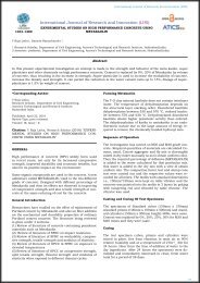
Methodology<br />
There are Different methodologies used by researchers<br />
to obtain a good design and economic performance<br />
of the valves by considering different valves<br />
failure criteria. Different types of failure and their<br />
causes are discussed in the following articles.<br />
Failure due to fatigue:<br />
The word fatigue is derived from the Latin fatigue<br />
which means “to tire”. In engineering terminology<br />
fatigue is a progressive structural damage of materials<br />
under cyclic loads. Important categories of<br />
fatigue include: Mechanical fatigue due to fluctuating<br />
stresses Creep fatigue due to cyclic loads at<br />
high temperatures; Thermal fatigue due to cyclic<br />
changes in material’s<br />
Temperature:<br />
Thermo-mechanical fatigue due to a combination of<br />
mechanical and thermal fatigue; corrosion fatigue<br />
due to cyclic loads applied on corroded materials,<br />
Fretting fatigue due to cyclic stresses together with<br />
the oscillation motion and frictional sliding between<br />
surfaces, etc.. Fatigue failure occurs at stresses that<br />
are well below the yield point of the material.<br />
I.C. Engine valves are subjected to repeated cyclic<br />
loading due to valve train dynamics. Repeated loading<br />
results in materials failing well below the yield<br />
strength. When the material is subjected to fatigue,<br />
one or more tiny cracks usually start developing in<br />
the material, and these grow until complete failure<br />
occurs. There are different types of fatigue mecha-<br />
32
International Journal of Research and Innovation (IJRI)<br />
nisms: thermal fatigue, high-cycle fatigue, low-cycle<br />
fatigue, surface fatigue, bending fatigue, corrosion<br />
fatigue, torsional fatigue, and fretting fatigue. In<br />
valves, some of the more common failures are due<br />
to thermal fatigue, corrosion fatigue, and low and<br />
high-cycle fatigue.<br />
What is a Valve Train?<br />
• It is the set of components in a 4-stroke engine,<br />
responsible for smooth functioning of the inlet and<br />
exhaust valve<br />
• It makes the valve to open and close as per the<br />
timing required for the correct functioning of the engine<br />
• The performance of the engine is severely depends<br />
proper functioning of valve train. Any malfunctioning<br />
in the valve train system could even lead to severe<br />
damage to the engine<br />
When it comes to fatigue, the S–N curves are often<br />
used to represent fatigue behavior. Because fatigue<br />
testing is time and energy consuming, predictive<br />
methods are often used.<br />
In many industries, the number of stress cycles for<br />
lifetime services are above 107 cycles, The fatigue<br />
fracture is basically observed under low cycle fatigue,<br />
normally less than 105 cycles. The fatigue life<br />
varies usually from 105 cycles to 107 cycles.<br />
Researchers have come up with a number of results<br />
for fatigue testing, one of them being discussed in<br />
this paper for material X45CrSi93 stainless steel for<br />
engine valves.<br />
Transient structural and thermal analysis will be<br />
conducted to determine structural and thermal defects<br />
individually, coupled field and fatigue analysis<br />
will be conducted to determine stress, deflection,<br />
strain, life, fatigue sensitivity and damage/error in<br />
combination both conditions at 5000 cycles as a<br />
single cycle.<br />
Fatigue cycles 1e 7 *5000 cycles as a single cycle.<br />
Introduction To Ic Engine Valve<br />
Valves Train Components for Internal Combustions<br />
Engines, which include<br />
1. Inlet and Exhaust Valves<br />
2. Valve Guides<br />
3. Tappets<br />
4. Camshafts<br />
What does an engine do?<br />
• It generates the power required for moving the<br />
vehicle or any other specific purpose.<br />
• It converts the energy contained in fuel to useful<br />
mechanical energy, by burning the fuel inside a<br />
combustion chamber.<br />
• An engine contains number of parts like Valves<br />
and other Valve train components, Piston, camshaft,<br />
Connecting rod, Cylinder block, Cylinder head<br />
etc., from which REVL supplying some of the<br />
valve train components to engine manufacturers<br />
About Valves:<br />
Engine Valve is one of the main parts which<br />
are used in all <strong>IC</strong> Engines. Each cylinder in the engine<br />
has one inlet and one exhaust valve. Now a<br />
days engine are designed with multi valves viz., two<br />
inlet and one exhaust or Two inlet and Two exhaust<br />
valves which prevents air pollution and improves<br />
engine efficiency.<br />
Function of Inlet Valve:<br />
The inlet which operates by the action of Tappet<br />
movement, allows air and fuel mixture into the cylinder.<br />
Function of Exhaust valve: The exhaust valve allows<br />
burnt gases to escape from the cylinder to atmosphere.<br />
Valve Efficiency:<br />
Depends on the following characteristics like Hardness,<br />
Face roundness and sliding properties capable<br />
to withstand high temperature etc.<br />
As compared to inlet, exhaust valve operates at high<br />
temperature as exhaust gases (around 800 Deg C)<br />
escape through it. As it resulting in early ways and<br />
gets corrosion, austenitic steel is used for manufacture<br />
of exhaust valve and martens tic steel is used<br />
for manufacture of inlet valve.<br />
The manufacturing process involves upset and forging,<br />
heat treatment and machining (turning and<br />
grinding) and special processes like TIG welding,<br />
Projection Welding, PTA Welding, Friction Welding,<br />
Induction Hardening and Nitriding.<br />
33
International Journal of Research and Innovation (IJRI)<br />
VALVE DIMENSIONS:<br />
DESIGN CALCULATIONS <strong>OF</strong> EXHAUST VALVE<br />
Introduction<br />
Because of exposure to hot exhaust gases<br />
and its effects on engine performance and volumetric<br />
efficiency, the exhaust valve of an internal combustion<br />
engine is one of the most critical parts. The<br />
design of exhaust valves depends on many parameters,<br />
Such as fluid dynamics of the exhaust gas, fatigue<br />
strength of the valve material, oxi- dation characteristics<br />
of the valve material, exhaust gas behavior of<br />
the material at high temperature, the configuration<br />
of the cylinder head, the coolant flow, the shape of<br />
the exhaust port, etc. .<br />
Design of outlet valve<br />
The most significant factor in the performance of<br />
an exhaust valve is its operating temperature. The<br />
importance of temperature can best be appreciated<br />
by its effect on the physical properties of the valve<br />
steel. The exhaust valve of an internal combustion<br />
engine operates under severe conditions of thermal,<br />
fatigue, and mechanical stresses. Large temperature<br />
gradients in the valve body are responsible<br />
for thermal stresses. Knowledge of the temperature<br />
field in different parts of an internal combustion engine<br />
is important in order to ascertain the points of<br />
highest thermal stress . A designer is always interested<br />
in obtaining an optimum condition so that the<br />
engine parts are not subjected to excessive stresses<br />
due to gas pressure (mechanical loading) and thermal<br />
loading. Meanwhile, the engine should not lose<br />
a large amount of heat through the parts.<br />
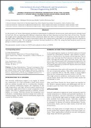
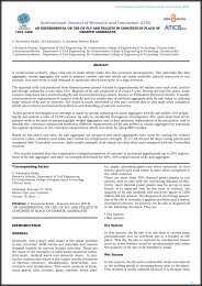
Description of the physical system<br />
The geometry of the exhaust valve is shown in figure<br />
1. The exhaust valve sits on the cylinder head<br />
of a combustion chamber. The engine coolant liquid<br />
passes around the cylinder liner and the water passages<br />
in the cylinder head. The valve pops up and<br />
down to let the exhaust gases leave the combustion<br />
chamber. The up-and-down<br />
34
International Journal of Research and Innovation (IJRI)<br />
Values of the boundary conditions used in the<br />
analysis<br />
The values of the boundary conditions used for the<br />
analysis are summarized in Table 1. The analysis<br />
was performed under the worst thermal loading<br />
condition of rated power. The engine specification<br />
and operating condition are summarized in Table 2.<br />
An analysis procedure using finite-element modeling<br />
techniques is developed to analyze of the exhaust<br />
valve thermal behavior.<br />
The analysis consists of:<br />
1. Construction of a suitable finite-element model<br />
2. Selection of material properties<br />
3. Engine specifications and operating conditions<br />
4. Application of the thermal boundary conditions<br />
5. Solution of the thermal finite-element model to<br />
obtain the transient temperature distribution<br />
6. Solution of the structural finite-element model to<br />
obtain the stresses resulting from the imposed temperature.<br />
Motion of the valve takes place with the help of a<br />
rocker lever which is connected to the push rod.<br />
The push rod rests over cams on the camshaft. The<br />
valve is spring loaded. The spring keeps the valve<br />
connected to the camshaft during its motion.<br />
After the expansion process, the exhaust gases, at<br />
high temperature, are purged through the exhaust<br />
valve and as a result the temperature of the exhaust<br />
valve increases. In order to avoid any damage to the<br />
exhaust valve due to this high temperature, heat<br />
must be continuously taken away from the valve.<br />
This is achieved when the valve is in contact with<br />
its seat. As the exhaust valves touch its seat, a significant<br />
drop in exhaust valve temperature occurs.<br />
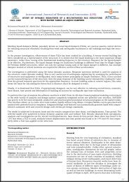
Numerical Approach And Procedure<br />
Assignment of the Boundary Conditions:-<br />
When the valve is in contact with the<br />
seat, the valve head is subjected to hot gases, with<br />
gas temperature Tg(h) and heat transfer coefficient<br />
hg(h). (h) is the crank The figures shows the fig.1 .<br />
Diagram of measured gas temperature in the cylinder<br />
Fig. Diagram of measured gas pressure in the<br />
cylinder<br />
Finite-Element Modeling<br />
The thermal stress analysis is performed using<br />
the parametric design language of the ansys software<br />
(apdl). By using this method for the simulation,<br />
the boundary conditions and the geometry can<br />
be changed in the model. Therefore, the model can<br />
be used at all operating conditions. For modeling of<br />
the exhaust valve, the axisymmetric modeling capability<br />
of the ansys software is used. An axisymmetric<br />
solid is generated by revolving a plane about an<br />
axis in the plane that is called the symmetry axis.<br />
The geometric and material properties are symmetric<br />
about the symmetry axis. In addition, it is considered<br />
that the thermal loadings are symmetric.<br />
Material Properties<br />
The physical and mechanical properties of the<br />
exhaust valve material are shown in Table 4. T is<br />
temperature, Su is ultimate strength, Sy is yield<br />
strength, n is Poisson’s ratio, a is the thermal expansion<br />
coefficient, K is the thermal conductive coefficient,<br />
C is specific heat, and q is density. The<br />
material properties are selected for austenitic steel<br />
whose UNS specification is S63008.<br />
Thermal Analysis<br />
Boundary conditions as explained above are<br />
applied to the model. Transient thermal analysis is<br />
initiated with initial temperature of 25 C. For thermal<br />
analysis a loop is used, each loop representing<br />
a cycle of engine operation. In each cycle, the<br />
crankshaft rotates twice and the camshaft rotates<br />
once. In each 242 of camshaft rotation the exhaust<br />
valve is closed, and in the remaining 118 the valve<br />
is open. Therefore, each cycle is divided into two<br />
parts (closed and open periods). The time<br />
35
International Journal of Research and Innovation (IJRI)<br />
Structural Analysis<br />
Thermal Analysis<br />
36
International Journal of Research and Innovation (IJRI)<br />
Fatigue Analysis<br />
Each loading history value refers to 5000*1e007<br />
cycles<br />
Material & valve manufacturing process<br />
Valve process flow with head to pin friction welding<br />
1. One halve of the bar is upsetted and then forged<br />
2 .Now the forged head is welded to another bar by<br />
friction welding.<br />
3. Deburring is done to remove the flash generated<br />
in friction welding<br />
4. .The valves obtained are straightened and given<br />
as input to rough<br />
Centreless grinding operation.<br />
Valve processing at Friction welding :<br />
37
International Journal of Research and Innovation (IJRI)<br />
The operations which are eliminated in “Head to<br />
pin” process are highlighted and indicated by an<br />
arrow.<br />
Benefits<br />
Material Saving:<br />
1.45665 - Rs. 2.59 / Valve<br />
2.40574 – Rs. 1.46 / Valve<br />
3.40579 – Rs. 1.40 / Valve<br />
Grinding Cost Saving :<br />
1.45665 - Rs. 0.99 / Valve<br />
2.40574 – Rs. 0.65 / Valve<br />
3.40579 – Rs. 0.65 / Valve<br />
Totally four operations eliminated for these part<br />
nos.<br />
Total savings per annum – Rs.20.0 lakhs<br />
In-direct benefit: This becomes a Poke-Yoke to avoid<br />
reverse material forging which is one of the critical<br />
customer complaints.<br />
Lead time reduced by 2 days<br />
Conclusion<br />
Valve Process Flow chart with Head to Pin Friction<br />
welding<br />
In this teases “<strong>FAILURE</strong> <strong>ANALYSIS</strong> <strong>OF</strong> <strong>IC</strong> <strong>ENGINE</strong><br />
<strong>VALVES</strong> <strong>BY</strong> <strong>USING</strong> <strong>FEA</strong>” is done and manufacturing<br />
segment is also presented for the valves.<br />
Initially litrecher survey is done to understand the<br />
process.<br />
Model is developed for further study in FEM.<br />
Static analysis is done on valve, valve with seat and<br />
fin segments by varying two materials.<br />
Study-state thermal analysis is done on valve, valve<br />
with seat and fin segments by varying two materials.<br />
Transient structural analysis is done on valve, valve<br />
with seat and fin segments by varying two materials<br />
@5000 cycles.<br />
Transient thermal analysis is done on valve, valve<br />
with seat and fin segments by varying two materials<br />
@5000 cycles.<br />
Coupled field analysis (combined analysis of static<br />
and thermal) is done on valve, valve with seat and<br />
fin segments by varying two materials.<br />
Fatigue analysis is done on valve, valve with seat<br />
and fin segments by varying two materials.<br />
Result for above analysis is presented in tables.<br />
Manufacturing process of valve is briefly explained.<br />
As per the analytical results valve with meg alloy fin<br />
is the right choice for maximum life.<br />
References<br />
1.Failure analysis of internal combustion engine valves: a review<br />
2.Naresh kr. Raghuwanshi1, ajay pandey2, r. K. Mandloi3 international<br />
journal of innovative research in science, engineering<br />
and technology vol. 1, Issue 2, december 2012<br />
38
International Journal of Research and Innovation (IJRI)<br />
3.Combating automotive engine valve recession by roger lewis<br />
and rob s.Dwyer-joyce university of sheffield dept. Of mechanical<br />
engineering sheffield, united kingdom engine valve recession<br />
4.Investigation of exhaust valve failure in heavy – duty diesel engine<br />
nurten vardar1, ahmet ekerim2 gazi university journal of<br />
science gu j sci 23(4):493-499 (2010)<br />
5.Modelling of the heat loads of the engine valves and the accuracy<br />
of calculations p. Gustof, a. Hornik* faculty of transport, department<br />
of vehicle service, silesian university of technology, ul.<br />
Krasińskiego 8, 40-019 katowice, poland received 03.04.2007;<br />
Published in revised form 01.08.2007 Journal of achievements<br />
in materials and manufacturing engineering<br />
6.Modelling and analysis of radial thermal stresses and temperature<br />
field in diesel engine valves with and without air cavity subodh<br />
kumar sharma1*, p. K. Saini2, n. K. Samria3<br />
20.C.G. Scott, a.T. Riga and h. Hong. The erosion-corrosion of<br />
nickel-base diesel engine exhaust valves. Wear 181-183 (1995)<br />
485-494.<br />
21.Zhao yun-cai and yan hang-zhi, experimental study on wear<br />
failure course of gas-valve/valve-seat in engine. J. Cent. South<br />
university. Technology 12 (2005) 243-246.<br />
22.P. Forsberg, p. Hollman, and s. Jacobson, wear mechanism<br />
study of exhaust valve system in modern heavy duty combustion<br />
engines. Wear 271 (2011) 2477– 2484<br />
23.Keyoung jin chun, jae hak kim, and jae soo hong, a study of<br />
exhaust valve and seat insert wear depending on cycle numbers.<br />
Wear 263 (2007) 1147– 1157<br />
Authors<br />
7.Failure analysis of an intake valve in a gasoline engine m.<br />
Azadi1*, m. Roozban2, a. Mafi3<br />
The journal of engine research<br />
Accepted: 20 march2013<br />
8.Failure analysis of exhaust valve spring of c.I.Engine patel<br />
sujal v.1, Pawar shrikant g.2 1 Research scholar, department<br />
of automobile engineering, rit sakharale 415414, sangli, maharashtra,<br />
india), 2 associate professor, department of automobile<br />
engineering, rit sakharale 415414, sangli, maharashtra, india)<br />
international journal of engineering research & technology (ijert)<br />
vol. 2 Issue 3, march - 2013 issn: 2278-0181 1<br />
9.Engine cylinder head thermal and structural stress analysis<br />
ing. Radek tichánek, ing. Miroslav španiel, csc. Czech technical<br />
university in prague technická 4, prague 6 cz-166 07, czech<br />
republic<br />
Kancharla Venkata Narayana<br />
Research Scholar<br />
(mtech in Thermal Engineering)<br />
Kits, Peddapuram(M) Tirupathi Village,<br />
Divili 533-433,<br />
Eg Dt,Ap,India.<br />
10.Computational visualization and simulation of diesel engines<br />
valve lift performance using cfd 1semin, 1rosli abu bakar and<br />
1abdul rahim ismail 1automotive focus group, faculty of mechanical<br />
engineering, university malaysia pahang, locked bag<br />
12, 25000 kuantan, pahang, malaysia american journal of applied<br />
sciences 5 (5): 532-539, 2008 issn 1546-9239<br />
11.M. I. Karamangil a. Avci and h. Bilal , investigation of the effect<br />
of different carbon film hickness on the exhaust valve. Heat<br />
mass transfer 44 (2008) 587–598<br />
12.H. J. C. Voorwalda, r. C. Coisse, and m. O. H.Cioffi. Fatigue<br />
strength of x45crsi93 stainless steel applied as internal combustion<br />
engine valves. Procedia engineering 10 (2011) 1256–1261.<br />
K.koteswara Rao.<br />
Assistant professor<br />
Kits, Peddapuram(M) Tirupathi Village,<br />
Divili 533-433,<br />
Eg Dt,Ap,India.<br />
13.V.Kazymyrovych, very high cycle fatigue of engineering materials.<br />
Karlstad university studies 2009:22. Issn 1403-8099, isbn<br />
978-91-7063-246-4<br />
14.Dowling, norman e.: Mechanical behavior of materials, engineering<br />
methods for deformation, fracture and fatigue. Prenticehall.<br />
15.D. J. Benac and r. A. Page, integrating design, maintenance,<br />
and failure analysis to increase structural valve integrity. Asm<br />
international 3 (2001) 31- 43<br />
16.Y.B. Liu, y.D. Li, s.X. Li, z.G. Yang,s.M. Chen, w.J. Hui, and<br />
y.Q. Weng , prediction of the s–n curves of high-strength steels in<br />
the very high cycle fatigue regim. International journal of fatigue<br />
32 (2010) 1351–1357<br />
Y Dhana Shekar,<br />
Assistant Professor ,<br />
Kits, Peddapuram(M) Tirupathi Village,<br />
Divili 533-433,<br />
Eg Dt,AP, India<br />
17.Oh geon kwon and moon sik han, failure analysis of the exhaust<br />
valve stem from a waukesha p9390 gsi gas engine. Engineering<br />
failure analysis 11 (2004) 439-447<br />
18.Z.W. Yu and x.L. Xu, failure analysis and metallurgical investigation<br />
of diesel ngine exhaust valves. Engineering failure analysis<br />
13 (2006) 673–682<br />
19.Alan v. Levy, solid particle erosion and erosion-corrosion of<br />
materials. Opyright1995 by asm international<br />
39