AN EXPERIMENTAL ON USE OF FLY ASH PELLETS IN CONCRETE IN PLACE OF
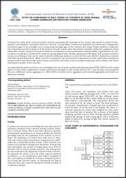
A construction industry plays vital role in India which leads into the economic developments. The materials like fine aggregate, coarse aggregate are used to prepare cement concrete which are easily available natural resources in our country, but now there is high demand in materials which have gone to a high scenario. The quantity of fly ash produced from thermal power plants in India is approximately 80 million tons each year, and its percentage utilization is less than 10%. Majority of fly ash produced is of Class F type. During the last few years, some cement companies have started using fly ash in manufacturing cement, known as ‘Pozzalanic Portland cement. It mainly concentrated on replacement of cement with fly ash but production of artificial aggregate with fly ash helps in utilizing large volume of fly ash in concrete. The world is much interested in this part recently due to this large scale utilization which also reduces environmental pollution and dwindling of natural resources.
A construction industry plays vital role in India which leads into the economic developments. The materials like fine
aggregate, coarse aggregate are used to prepare cement concrete which are easily available natural resources in our
country, but now there is high demand in materials which have gone to a high scenario.
The quantity of fly ash produced from thermal power plants in India is approximately 80 million tons each year, and its
percentage utilization is less than 10%. Majority of fly ash produced is of Class F type. During the last few years, some
cement companies have started using fly ash in manufacturing cement, known as ‘Pozzalanic Portland cement. It mainly
concentrated on replacement of cement with fly ash but production of artificial aggregate with fly ash helps in utilizing
large volume of fly ash in concrete. The world is much interested in this part recently due to this large scale utilization
which also reduces environmental pollution and dwindling of natural resources.

You also want an ePaper? Increase the reach of your titles
YUMPU automatically turns print PDFs into web optimized ePapers that Google loves.
International Journal of Research and Innovation (IJRI)<br />
Benefits<br />
• Reduces bleeding,<br />
• Increase time of setting,<br />
• Improve workability,<br />
• Reduces segregation in plastic concrete,<br />
• Increases ultimate strength,<br />
• Reduces drying shrinkage and permeability,<br />
• Lowers the heat of hydration<br />
Fine aggregate<br />
The sand used throughout the experimental work ws obtained<br />
from Chittoor, Chittoor district, Andhra Pradesh.<br />
Sand was thoroughly washed with tap water to remove<br />
impurities like decayed vegetable matter, humus, organic<br />
matter and deleterious materials like clay, fine silt and<br />
fine dust and was oven dried for 24 hours and cooled to<br />
room temperature and hence care was taken for the sand<br />
used in the investigation.<br />
In the present work the size of the sand is passing through<br />
4.75 and retaining on 150mm as per IS sieve. The specific<br />
gravity of sand is 2.6. sand is tested for specific gravity, in<br />
accordance with IS: 2386-1963(Part I and II)<br />
Sand Properties<br />
S.NO Properties Sand values<br />
1 Specific gravity 2.6<br />
2 Water absorption 1.0<br />
(%)<br />
3 Bulk density (Kg/ 1.460<br />
m3)<br />
4 Fineness modulus<br />
(%)<br />
3.12<br />
Compressive strength<br />
Remove the specimen from water after specified curing<br />
time and wipe out excess water from the surface. Take the<br />
dimension of the specimen to the nearest 0.2m. Clean the<br />
bearing surface of the testing machine. Place the specimen<br />
in the machine in such a manner that the load shall<br />
be applied to the opposite sides of the cube cast. Align the<br />
specimen centrally on the base plate of the machine. Rotate<br />
the movable portion gently by hand so that it touches<br />
the top surface of the specimen. Apply the load gradually<br />
without shock and continuously at the rate of 140kg/<br />
cm2/minute till the specimen fails. Record the maximum<br />
load and note any unusual features in the type of failure.<br />
Samples Testing<br />
Concrete cube specimens<br />
In carrying out the X-ray diffraction, the concrete samples<br />
are first grinded into powder form. The sample size<br />
is normally 0.002mm to 0.005 mm and then they are put<br />
into the small packets. X-ray diffraction (XRD) data for<br />
grind samples were tested on Panalytical’s X’Pert Pro with<br />
Cu Kα radiation at IIT Ropar, Punjab. The samples are<br />
scanned in the range of 2Ѳ = 5 - 60˚ at the scanning speed<br />
of 2˚/min.<br />
X-ray powder diffraction (XRD) is a rapid analytical technique<br />
primarily used for phase identification of a crystalline<br />
material and can provide information on unit cell<br />
dimensions. The analyzed material is finely ground, homogenized,<br />
and average bulk composition is determined<br />
4.4.3.1 Fundamental Principles of X-ray Powder Diffraction<br />
(XRD)<br />
Max von Laue, in 1912, discovered that crystalline substances<br />
act as three-dimensional diffraction gratings for<br />
X-ray wavelengths similar to the spacing of planes in a<br />
crystal lattice. X-ray diffraction is now a common technique<br />
for the study of crystal structures and atomic spacing.<br />
X-ray diffraction is based on constructive interference of<br />
monochromatic X-rays and a crystalline sample. These<br />
X-rays are generated by a cathode ray tube, filtered to<br />
produce monochromatic radiation, collimated to concentrate,<br />
and directed toward the sample. The interaction of<br />
the incident rays with the sample produces constructive<br />
interference (and a diffracted ray) when conditions satisfy<br />
Bragg's Law (nλ=2d sin θ). This law relates the wavelength<br />
of electromagnetic radiation to the diffraction angle<br />
and the lattice spacing in a crystalline sample. These diffracted<br />
X-rays are then detected, processed and counted.<br />
By scanning the sample through a range of 2θangles, all<br />
possible diffraction directions of the lattice should be attained<br />
due to the random orientation of the powdered material.<br />
Conversion of the diffraction peaks to d-spacings<br />
allows identification of the mineral because each mineral<br />
has a set of unique d-spacings. Typically, this is achieved<br />
by comparison of d-spacings with standard reference patterns.<br />
All diffraction methods are based on generation of X-Rays<br />
in an X-ray tube. These X-rays are directed at the sample,<br />
and the diffracted rays are collected. A key component of<br />
all diffraction is the angle between the incident and diffracted<br />
rays. Powder and single crystal diffraction vary in<br />
instrumentation beyond this.<br />
236