
You also want an ePaper? Increase the reach of your titles
YUMPU automatically turns print PDFs into web optimized ePapers that Google loves.
„<strong>UMTS</strong> <strong>Signaling</strong>“ – Abstract – Wiley & Sons, 2005 – ISBN 0-470-01351-6<br />
<strong>UMTS</strong> <strong>Signaling</strong><br />
<strong>UMTS</strong> Interfaces, Protocols,<br />
Message Flows and Procedures<br />
Analyzed and Explained<br />
„<strong>UMTS</strong> <strong>Signaling</strong>“ – Abstract – Wiley & Sons, 2005 – ISBN 0-470-01351-6
„<strong>UMTS</strong> <strong>Signaling</strong>“ – Abstract – Wiley & Sons, 2005 – ISBN 0-470-01351-6<br />
Ralf Kreher<br />
<strong>Tektronix</strong>, Inc., Germany<br />
Torsten Ruedebusch<br />
<strong>Tektronix</strong>, Inc., Germany<br />
Copyright © 2005, <strong>Tektronix</strong>, Inc. All rights reserved. <strong>Tektronix</strong> products<br />
are covered by U.S. and foreign patents, issued and pending. Information<br />
in this publication supersedes that in all previously published material.<br />
„<strong>UMTS</strong> <strong>Signaling</strong>“ – Abstract – Wiley & Sons, 2005 – ISBN 0-470-01351-6
„<strong>UMTS</strong> <strong>Signaling</strong>“ – Abstract – Wiley & Sons, 2005 – ISBN 0-470-01351-6<br />
Specification and price change privileges reserved. TEKTRONIX and TEK<br />
are registered trademarks of <strong>Tektronix</strong>, Inc. All other trade names<br />
referenced are the service marks, trademarks or registered trademarks<br />
of their respective companies.<br />
„<strong>UMTS</strong> <strong>Signaling</strong>“ – Abstract – Wiley & Sons, 2005 – ISBN 0-470-01351-6
„<strong>UMTS</strong> <strong>Signaling</strong>“ – Abstract – Wiley & Sons, 2005 – ISBN 0-470-01351-6<br />
CONTENT<br />
ACKNOWLEDGMENTS<br />
ABOUT THE AUTHORS<br />
1 <strong>UMTS</strong> BASICS<br />
1.1 STANDARDS<br />
1.2 NETWORK ARCHITECTURE<br />
1.2.1 GSM<br />
1.2.2 <strong>UMTS</strong> Release 99<br />
1.2.3 <strong>UMTS</strong> Release 4<br />
1.2.4 <strong>UMTS</strong> Release 5<br />
1.2.5 <strong>UMTS</strong> Release 6<br />
1.3 <strong>UMTS</strong> INTERFACES<br />
1.3.1 Iu Interface<br />
1.3.2 Iub Interface<br />
1.3.3 Iur Interface<br />
1.4 <strong>UMTS</strong> DOMAIN ARCHITECTURE<br />
1.5 UTRAN<br />
1.5.1 RNC<br />
1.5.2 Node B<br />
1.5.3 Area Concept<br />
1.5.4 <strong>UMTS</strong> User Equipment & USIM<br />
1.5.5 Mobiles<br />
1.5.6 QoS Architecture<br />
1.6 <strong>UMTS</strong> SECURITY<br />
1.6.1 Historic development<br />
1.6.2 <strong>UMTS</strong> Security Architecture<br />
1.6.3 Authentication and Key Agreement (AKA)<br />
1.6.4 Kasumi/Misty<br />
1.6.5 Integrity - Air Interface Integrity Mechanism<br />
1.6.6 Confidentiality - Encryption (Ciphering) on Uu and Iub<br />
1.6.7 <strong>UMTS</strong> Network Transactions<br />
1.7 RADIO INTERFACE BASICS<br />
1.7.1 Duplex Methods<br />
1.7.2 Multiple Access Methods<br />
1.7.3 <strong>UMTS</strong> CDMA<br />
1.7.4 CDMA Spreading<br />
1.7.5 Micro Diversity - Multipath<br />
1.7.6 Micro Diversity – Softer Handover<br />
1.7.7 Macro Diversity – Soft Handover<br />
1.7.8 <strong>UMTS</strong> Spreading<br />
1.7.9 Scrambling<br />
1.7.10 Coding Summary<br />
1.7.11 Signal to Interference<br />
1.7.12 Cell Breathing<br />
1.7.13 <strong>UMTS</strong> Channels<br />
1.7.14 Transport Channels<br />
1.7.15 Common Transport Channels<br />
1.7.16 Dedicated Transport Channels<br />
1.7.17 Initial UE Radio Access<br />
1.7.18 Power Control<br />
1.7.19 UE Random Access<br />
1.7.20 Power Control in Soft Handover<br />
1.8 <strong>UMTS</strong> NETWORK PROTOCOL ARCHITECTURE<br />
1.8.1 Iub – Control Plane<br />
1.8.2 Iub – User Plane<br />
1.8.3 Iur – User-/Control Plane<br />
„<strong>UMTS</strong> <strong>Signaling</strong>“ – Abstract – Wiley & Sons, 2005 – ISBN 0-470-01351-6
„<strong>UMTS</strong> <strong>Signaling</strong>“ – Abstract – Wiley & Sons, 2005 – ISBN 0-470-01351-6<br />
1.8.4 IuCS – User-/Control-Plane<br />
1.8.5 IuPS – User-/Control-Plane<br />
1.8.6 E – User-/Control-Plane<br />
1.8.7 Gn – User-/Control-Plane<br />
1.9 ATM<br />
1.9.1 ATM Cell<br />
1.9.2 ATM Layer Architecture<br />
1.9.3 ATM Adaption Layer (AAL)<br />
1.9.4 AAL2<br />
1.9.5 AAL5<br />
1.10 USER PLANE FRAMING PROTOCOL<br />
1.10.1 Frame Architecture<br />
1.10.2 FP Control Frame Architecture<br />
1.11 MEDIUM ACCESS PROTOCOL (MAC)<br />
1.11.1 MAC Architecture<br />
1.11.2 MAC Data PDU<br />
1.11.3 MAC Header Alternatives<br />
1.12 RADIO LINK CONTROL (RLC)<br />
1.12.1 RLC Services<br />
1.12.2 RLC Functions<br />
1.12.3 RLC Architecture<br />
1.12.4 RLC Data PDUs<br />
1.12.5 Other RLC PDUs<br />
1.13 SERVICE SPECIFIC CONNECTION ORIENTED PROTOCOL (SSCOP)<br />
1.13.1 Example SSCOP<br />
1.14 SERVICE SPECIFIC COORDINATION FUNCTION (SSCF)<br />
1.15 MESSAGE TRANSFER PART LEVEL 3 – BROADBAND (MTP3-B)<br />
1.16 INTERNET PROTOCOL (IP)<br />
1.16.1 IPV4 Frame Architecture<br />
1.17 SIGNALLING TRANSPORT CONVERTER (STC)<br />
1.18 SIGNALLING CONNECTION CONTROL PART (SCCP)<br />
1.18.1 Example SCCP<br />
1.19 ABSTRACT SYNTAX NOTATION ONE IN <strong>UMTS</strong> (ASN.1)<br />
1.19.1 ASN.1 Basic Encoding Rules (BER)<br />
1.19.2 ASN.1 Packed Encoding Rules (PER)<br />
1.20 RADIO RESOURCE CONTROL (RRC)<br />
1.20.1 RRC States<br />
1.20.2 System information blocks (SIB)<br />
1.21 NODE B APPLICATION PART NBAP<br />
1.21.1 NBAP functions<br />
1.21.2 NBAP Elementary Procedures (EPs)<br />
1.21.3 Example - NBAP<br />
1.22 RADIO NETWORK SUBSYSTEM APPLICATION PART (RNSAP)<br />
1.22.1 RNSAP Functions<br />
1.22.2 Example RNSAP Procedures<br />
1.23 RADIO ACCESS NETWORK APPLICATION PART (RANAP)<br />
1.23.1 RANAP Elementary Procedures (EPs)<br />
1.23.2 Example – RANAP Procedure<br />
1.24 ATM ADAPTATION LAYER TYPE 2 – LAYER 3 (AAL2L3/ALCAP)<br />
1.24.1 AAL2L3 Message Format<br />
1.24.2 Example – AAL2L3 Procedure<br />
1.25 IU USER PLANE PROTOCOL<br />
1.25.1 Iu UP Transparent Mode<br />
1.25.2 Iu UP Support Mode Data Frames<br />
1.25.3 Iu UP Support Mode Control Frames<br />
1.25.4 Example – Iu UP Support Mode Message Flow<br />
1.26 ADAPTIVE MULTI-RATE CODEC – AMR<br />
„<strong>UMTS</strong> <strong>Signaling</strong>“ – Abstract – Wiley & Sons, 2005 – ISBN 0-470-01351-6
„<strong>UMTS</strong> <strong>Signaling</strong>“ – Abstract – Wiley & Sons, 2005 – ISBN 0-470-01351-6<br />
1.26.1 AMR IF 1 Frame Architecture<br />
1.27 TERMINAL ADAPTION FUNCTION (TAF)<br />
1.28 RADIO LINK PROTOCOL – RLP<br />
1.29 PACKET DATA CONVERGENCE PROTOCOL (PDCP)<br />
1.29.1 PDCP PDU Format<br />
1.30 BROADCAST / MULTICAST CONTROL (BMC)<br />
1.30.1 BMC Architecture<br />
1.31 CIRCUIT SWITCHED MOBILITY MANAGEMENT (MM)<br />
1.32 CIRCUIT SWITCHED CALL CONTROL (CC)<br />
1.33 EXAMPLE - MOBILE ORIGINATED CALL (CIRCUIT SWITCHED)<br />
1.34 PACKET SWITCHED MOBILITY MANAGEMENT (GMM)<br />
1.35 PACKET SWITCHED SESSION MANAGEMENT (SM)<br />
1.36 EXAMPLE - ACTIVATE PDP CONTEXT (PACKET SWITCHED)<br />
2 SHORT INTRODUCTION TO NETWORK MONITORING, TROUBLE SHOOTING AND<br />
NETWORK OPTIMIZATION<br />
2.1 IUB MONITORING<br />
2.1.1 IMA<br />
2.1.2 Fractional ATM<br />
2.1.3 Loadsharing and Addressing on Iub<br />
2.1.4 Troubleshooting Iub Monitoring Scenarios<br />
2.2 IU MONITORING<br />
2.2.1 Troubleshooting Iu Monitoring<br />
3 <strong>UMTS</strong> UTRAN SIGNALING PROCEDURES<br />
3.1 IUB - NODE B SETUP<br />
3.1.1 Overview<br />
3.1.2 Message Flow<br />
3.2 IUB - IMSI / GPRS ATTACH PROCEDURE<br />
3.2.1 Overview<br />
3.2.2 Message Flow<br />
3.3 IUB CS - MOBILE ORIGINATED CALL<br />
3.3.1 Overview<br />
3.3.2 Message Flow<br />
3.4 IUB CS – MOBILE TERMINATED CALL<br />
3.4.1 Overview<br />
3.4.2 Message Flow<br />
3.5 IUB PS - PDP CONTEXT ACTIVATION/DEACTIVATION<br />
3.5.1 Overview<br />
3.5.2 Message Flow<br />
3.6 IUB - IMSI/GPRS DETACH PROCEDURE<br />
3.6.1 Overview<br />
3.6.2 Message Flow<br />
3.7 RRC MEASUREMENT PROCEDURES<br />
3.8 IUB - PHYSICAL CHANNEL RECONFIGURATION (PDCP)<br />
3.8.1 Message Flow<br />
3.9 CHANNEL TYPE SWITCHING<br />
3.9.1 Overview<br />
3.9.2 Message Flow<br />
3.10 IUB - MOBILE ORIGINATED CALL WITH SOFT HANDOVER<br />
(INTER NODE B, INTRA RNC)<br />
3.10.1 Overview<br />
3.10.2 Message Flow<br />
3.11 IUB – SOFTER HANDOVER<br />
3.11.1 Overview<br />
3.11.2 Message Flow<br />
3.12 IUB-IU - LOCATION UPDATE<br />
3.12.1 Message Flow<br />
3.13 IUB-IU – MOBILE ORIGINATED CALL<br />
„<strong>UMTS</strong> <strong>Signaling</strong>“ – Abstract – Wiley & Sons, 2005 – ISBN 0-470-01351-6
„<strong>UMTS</strong> <strong>Signaling</strong>“ – Abstract – Wiley & Sons, 2005 – ISBN 0-470-01351-6<br />
3.13.1 Overview<br />
3.13.2 Overview<br />
3.14 IUB-IU – MOBILE TERMINATED CALL<br />
3.14.1 Overview<br />
3.14.2 Message Flow<br />
3.15 IUB-IU – ATTACH<br />
3.15.1 Overview<br />
3.15.2 Message Flow<br />
3.16 IUB-IU – PDP CONTEXT ACTIVATION/DEACTIVATION<br />
3.16.1 Overview<br />
3.16.2 Message Flow<br />
3.17 IUB-IU – DETACH<br />
3.17.1 Overview<br />
3.17.2 Message Flow<br />
3.18 IUB-IUR - SOFT HANDOVER (INTER NODE B, INTER RNC)<br />
3.18.1 Overview<br />
3.18.2 Message Flow<br />
3.19 IUB-IU – FORWARD HANDOVER (INTER NODE B, INTER RNC)<br />
3.19.1 Overview<br />
3.19.2 Message Flow<br />
3.20 SRNS RELOCATION (UE NOT INVOLVED)<br />
3.20.1 Overview<br />
3.20.2 Message Flow<br />
3.21 SRNS RELOCATION (UE INVOLVED)<br />
3.21.1 Overview<br />
3.21.2 Message Flow<br />
3.22 SHORT MESSAGE SERVICE (SMS) IN <strong>UMTS</strong> NETWORKS<br />
3.22.1 SMS Network Architecture Overview<br />
3.22.2 SMS Protocol Architecture<br />
3.22.3 Mobile Originated Short Message<br />
3.22.4 Mobile Terminated Short Message<br />
4 SIGNALING PROCEDURES IN THE 3G CORE NETWORK<br />
4.1 ISUP/BICC CALL SETUP<br />
4.1.1 Address Parameters for ISUP/BICC Messages<br />
4.1.2 ISUP Call (Successful)<br />
4.1.3 ISUP Call Unsuccessful<br />
4.1.4 BICC Call Setup on E-Interface including IuCS <strong>Signaling</strong><br />
4.2 GN INTERFACE SIGNALING<br />
4.3 PROCEDURES ON GS INTERFACE<br />
4.4 SIGNALING ON INTERFACES TOWARDS HLR<br />
4.4.1 Addressing on MAP Interfaces<br />
4.4.2 MAP Architecture<br />
4.4.3 MAP <strong>Signaling</strong> Example<br />
4.5 INTER-3G_MSC HANDOVER PROCEDURE<br />
4.6 INTER-3G-2G-3G_MSC HANDOVER PROCEDURE<br />
4.7 CUSTOMIZED APPLICATION FOR MOBILE NETWORK ENHANCED LOGIC (CAMEL)<br />
4.7.1 IN/CAMEL Network Architecture<br />
4.7.2 CAMEL Basic Call State Model<br />
4.7.3 Charging Operation using CAMEL<br />
4.7.4 CAMEL <strong>Signaling</strong> Example for GPRS Charging<br />
5 GLOSSARY<br />
6 BIBLIOGRAPHY<br />
6.1 TECHNICAL SPECIFICATIONS<br />
6.1.1 Extract of <strong>UMTS</strong>-related Specifications<br />
6.2 LITERATURE<br />
6.3 OTHER WWW SOURCES<br />
7 INDEX<br />
„<strong>UMTS</strong> <strong>Signaling</strong>“ – Abstract – Wiley & Sons, 2005 – ISBN 0-470-01351-6
„<strong>UMTS</strong> <strong>Signaling</strong>“ – Abstract – Wiley & Sons, 2005 – ISBN 0-470-01351-6<br />
„<strong>UMTS</strong> <strong>Signaling</strong>“ – Abstract – Wiley & Sons, 2005 – ISBN 0-470-01351-6
„<strong>UMTS</strong> <strong>Signaling</strong>“ – Abstract – Wiley & Sons, 2005 – ISBN 0-470-01351-6<br />
PREFACE<br />
The successful trial, deployment, operation and troubleshooting of 3G or <strong>UMTS</strong> infrastructures and<br />
applications is one of the most exciting, fascinating and challenging tasks in today’s mobile<br />
communications. Interoperability, roaming or QoS awareness between multi operators and multi<br />
technology network infrastructures are just a few of the problems, which need to be met. In today’s<br />
early deployments of <strong>UMTS</strong> networks five main categories of problems can be differentiated:<br />
(1) Network Element Instability<br />
(2) Network Element Interworking<br />
(3) Multi Vendor Interworking (MVI)<br />
(4) Configuration Faults<br />
(5) Network Planning Faults<br />
To meet these challenges, it is vital to understand and analyze the message flows associated with<br />
<strong>UMTS</strong>.<br />
“<strong>UMTS</strong> <strong>Signaling</strong>” focuses on providing an overview and reference to <strong>UMTS</strong>, details of the standards,<br />
the network architecture, objectives and functions of the different interfaces and protocols. Additionally<br />
it comprehensively describes various procedures from Node B Setup to different Handover types in<br />
the UTRAN and the Core Network. The focus on wireline interfaces is unique in the market. All<br />
signaling sequences are based upon <strong>UMTS</strong> traces from various <strong>UMTS</strong> networks (trial and commercial<br />
networks) around the world. With this book the reader has access to the first universal <strong>UMTS</strong> protocol<br />
sequence reference, which allows to quickly differentiate valid from invalid call control procedures. In<br />
addition all main signaling stages are being explained, many of which had been left unclear in the<br />
standards so far and valuable tips for protocol monitoring are provided.<br />
What will you get out of “<strong>UMTS</strong> <strong>Signaling</strong>”?<br />
(1) A comprehensive overview on <strong>UMTS</strong> UTRAN and Core networks<br />
o Latest updates for Rel. 4, Rel. 5 and Rel. 6 features are included<br />
o Description of the real-world structure of ATM transport network on Iub and Iu interfaces<br />
o Valuable tips and tricks for practical interface monitoring<br />
(2) In-depth description of the tasks and functions of <strong>UMTS</strong> interfaces and Protocols<br />
(3) A deep protocol knowledge improvement<br />
(4) Potential to analyze specific protocol messages<br />
(5) Support to reduce time and effort to detect and analyze problems<br />
(6) Explanations how to locate problems in the network.<br />
(7) Comprehensive descriptions and documentation of <strong>UMTS</strong> reference scenarios for different <strong>UMTS</strong><br />
procedures<br />
o UTRAN <strong>Signaling</strong> Procedures<br />
� Description of RRC measurement procedures for radio network optimization<br />
� Analysis and explanation of PS calls with so-called channel type switching, which<br />
is one of the most common performance problems of packet switched services in<br />
today's 3G networks<br />
� SRNS Relocation scenarios - including full description of RANAP and RRC<br />
containers<br />
� More than 35 decoded message examples using <strong>Tektronix</strong>' protocol testers give a<br />
deep insight into control plane protocols on different layers<br />
o Core Network <strong>Signaling</strong> Procedures<br />
� In-depth evaluations on mobility management, session management and call<br />
control procedures<br />
� Example call flows of the CS domain including practical ideas for troubleshooting<br />
� Tunnel management on Gn interfaces<br />
� Mobility management using optional Gs interface<br />
� Discussion on core network switch (MSC, SGSN) and database (HLR, VLR)<br />
information exchange over Mobile Application Part (MAP).<br />
„<strong>UMTS</strong> <strong>Signaling</strong>“ – Abstract – Wiley & Sons, 2005 – ISBN 0-470-01351-6
„<strong>UMTS</strong> <strong>Signaling</strong>“ – Abstract – Wiley & Sons, 2005 – ISBN 0-470-01351-6<br />
� Short introduction to 3G intelligent services with CAMEL Application Part (CAP)<br />
protocol<br />
� Comprehensive description of Inter-MSC handover procedures for 3G-3G, 3G-<br />
GSM and GSM-3G handovers<br />
� Detailed description of RANAP, BSSAP and RRC information<br />
“<strong>UMTS</strong> <strong>Signaling</strong>” readers should be rather familiar with <strong>UMTS</strong> technology at a fairly detailed level as<br />
the book is directed to <strong>UMTS</strong> experts, who need to analyze <strong>UMTS</strong> signaling procedures at the most<br />
detailed level. This is why only an introductionary overview section discusses the <strong>UMTS</strong> Network<br />
architecture, the objectives and functions of the different interfaces and the various <strong>UMTS</strong> protocols.<br />
Then the book leads right into the main part – the analysis of all main signaling processes in a <strong>UMTS</strong><br />
networks, so called <strong>UMTS</strong> scenarios. All main procedures –from Node B Setup to Hard Handover- are<br />
described and explained comprehensively.<br />
The combination of a network of <strong>UMTS</strong> experts around the world from many different companies with<br />
<strong>Tektronix</strong>’ many years of experience in protocol analysis have resulted in this unique book,<br />
compendium and reference. I hope it will prove helpful for the successful implementation and<br />
deployment of <strong>UMTS</strong>.<br />
Alois Hauk<br />
General Manager Monitoring and Protocol Test<br />
<strong>Tektronix</strong> Inc.<br />
If you have any kind of feedback or questions feel free to send us an email to<br />
umts-signaling@tektronix.com<br />
„<strong>UMTS</strong> <strong>Signaling</strong>“ – Abstract – Wiley & Sons, 2005 – ISBN 0-470-01351-6
„<strong>UMTS</strong> <strong>Signaling</strong>“ – Abstract – Wiley & Sons, 2005 – ISBN 0-470-01351-6<br />
ACKNOWLEDGMENTS<br />
The <strong>Tektronix</strong> Network Diagnostics Academy trained already hundreds of students in <strong>UMTS</strong> and other<br />
experience mobile technologies and in testing mobile networks.<br />
The experience from these trainings and our close customer relations pointed out, that a book on<br />
<strong>UMTS</strong> <strong>Signaling</strong> is desperately needed.<br />
We collected all the material that was available at <strong>Tektronix</strong> and that was provided by our partners at<br />
network equipment vendors and network operators to add it to this unique selection.<br />
The authors would like to acknowledge the effort and time invested by all our colleagues<br />
at <strong>Tektronix</strong>, who have contributed to this book.<br />
Special thanks go to Jens Irrgang and Christian Villwock, <strong>Tektronix</strong> MPT, Berlin for their<br />
Co-Authorship and their valuable advice and input.<br />
Without Juergen Placht (Sanchar GmbH) this book would not exist. His unbelievable knowledge,<br />
experience and efforts in preparing the very first slide sets for <strong>UMTS</strong> scenarios laid the basis for the<br />
material you have now in front of you.<br />
Additionally, the material that Magnar Norderhus, Hummingbird, Duesseldorf, prepared for the first<br />
<strong>UMTS</strong> Training for <strong>Tektronix</strong> was the very first source that we have “blown up” for part one of this<br />
book.<br />
Many thanks go to Joerg Nestle Product Design, Munich, for doing a great job in the creation of all the<br />
graphics.<br />
We would like to express thanks to Othmar Kyas, Marketing Manager of <strong>Tektronix</strong><br />
Monitor & Protocol Test for his strong believe in the <strong>Tektronix</strong> Network Diagnostics Academy, in<br />
“<strong>UMTS</strong> <strong>Signaling</strong>” and for challenging us to make this book become real.<br />
Of course we must not forget to thank Mark Hammond and the team at Wiley. Mark wanted us to do<br />
the book and kept us moving, even though it took so much time to get all the permissions aligned with<br />
<strong>Tektronix</strong>.<br />
Last but not least a special 'thank you' to our families and friends for their ongoing and infinite patience<br />
and their support throughout this project.<br />
Berlin, Germany<br />
Ralf Kreher, Torsten Ruedebusch<br />
„<strong>UMTS</strong> <strong>Signaling</strong>“ – Abstract – Wiley & Sons, 2005 – ISBN 0-470-01351-6
„<strong>UMTS</strong> <strong>Signaling</strong>“ – Abstract – Wiley & Sons, 2005 – ISBN 0-470-01351-6<br />
ABOUT THE AUTHORS<br />
Ralf Kreher<br />
Manager for Customer Training<br />
Mobile Protocol Test<br />
<strong>Tektronix</strong>, Inc.<br />
Ralf Kreher leads the Customer Training Department for <strong>Tektronix</strong>’ Mobile Protocol Test business<br />
(MPT). He is responsible for the world-class seminar portfolio for mobile technologies and<br />
measurement products.<br />
Before joining <strong>Tektronix</strong>, Kreher held a trainer assignment for switching equipment at Teles AG.<br />
Kreher holds a Communication Engineering Degree of the Technical College Deutsche Telekom<br />
Leipzig. He currently resides in Germany.<br />
Torsten Ruedebusch<br />
Head of Knowledgeware and Training Department<br />
Mobile Protocol Test<br />
<strong>Tektronix</strong>, Inc.<br />
Torsten Ruedebusch is the head of the Knowledgeware and Training Department for <strong>Tektronix</strong>’ Mobile<br />
Protocol Test business (MPT). He is responsible for providing leading edge technology and product<br />
seminars and the creation of knowledgeware products, created from the extensive <strong>Tektronix</strong>’<br />
expertise.<br />
Before joining <strong>Tektronix</strong>, Ruedebusch held an application engineer assignment at Siemens CTE.<br />
Ruedebusch holds a Communication Engineering Degree of the Technical College Deutsche Telekom<br />
Berlin. He currently resides in Germany.<br />
„<strong>UMTS</strong> <strong>Signaling</strong>“ – Abstract – Wiley & Sons, 2005 – ISBN 0-470-01351-6
„<strong>UMTS</strong> <strong>Signaling</strong>“ – Abstract – Wiley & Sons, 2005 – ISBN 0-470-01351-6<br />
1 <strong>UMTS</strong> BASICS<br />
<strong>UMTS</strong> is real. In several parts of the world we can walk in the stores of mobile network operators or<br />
resellers and take <strong>UMTS</strong> PC-Cards or even 3G phones home and use them instantly. Every day the<br />
number of equipment and their feature sets gets broader. The “dream” of multimedia on mobile<br />
connections, online gaming, video conferencing or even real-time video becomes reality.<br />
With rapid technical innovation the mobile telecommunication sector has continued to grow and evolve<br />
strongly.<br />
The technologies used to provide wireless voice and data services to subscribers, such as Time<br />
Division Multiple Access (TDMA), Universal Mobile Telecommunications Systems (<strong>UMTS</strong>) and Code<br />
Division Multiple Access (CDMA), continue to grow in their complexity. This complexity continues to<br />
impart a time-consuming hurdle to overcome when moving from 2G to 2.5G and to third-generation<br />
(3G) networks.<br />
GSM (Global System for Mobile Communication) is the most widely installed wireless technology in<br />
the world. Some estimates put GSM market share at up to 80%. Long dominant in Europe, GSM is<br />
now gaining a foothold in Brazil and is expanding its penetration in the North American market.<br />
One reason for this trend is the emergence of reliable, profitable 2.5G GPRS elements and services.<br />
Adding a 2.5G layer to the existing GSM foundation has been a cost-effective solution to current<br />
barriers while still bringing desired data services to market. The enhancement to EGPRS (EDGE)<br />
allows a speed of 384kbit/s. This is the maximum limit. Now EDGE goes under pressure, because<br />
High Speed Downlink Packet Access (HSDPA) and its speed of 2Mbit/s will take huge ports of the<br />
market share once it is largely available.<br />
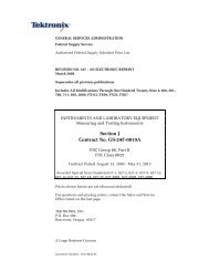
So, the EGPRS operators will sooner or later switch to 3G <strong>UMTS</strong> (Figure 1.1) services, the latest of<br />
which is <strong>UMTS</strong> Release 6 (R6). This transition brings new opportunities and new testing challenges,<br />
both in terms of revenue potential and addressing interoperability issues to ensure QoS.<br />
With 3G mobile networks, the revolution of mobile communication has begun. 4G and 5G networks<br />
will make the network transparent to the user’s applications. In addition to horizontal handovers (for<br />
example between Node Bs), handovers will occur vertically between applications and the terrestrial<br />
UTRAN (<strong>UMTS</strong> Terrestrial Radio Access) will be extended by a satellite-based RAN (Radio Access<br />
Network), ensuring global coverage.<br />
Figure 1-1 - Component Overview of a <strong>UMTS</strong> Network<br />
Every day the number of commercial networks in different parts of the world increases rapidly.<br />
Therefore, network operators and equipment suppliers are desperate to understand how to handle<br />
and analyze <strong>UMTS</strong> signaling procedures in order to get the network into operation, detect errors, and<br />
troubleshoot faults.<br />
„<strong>UMTS</strong> <strong>Signaling</strong>“ – Abstract – Wiley & Sons, 2005 – ISBN 0-470-01351-6
„<strong>UMTS</strong> <strong>Signaling</strong>“ – Abstract – Wiley & Sons, 2005 – ISBN 0-470-01351-6<br />
Those experienced with GSM will recognize many similarities with <strong>UMTS</strong>, especially in Non-Access-<br />
Stratum or NAS-messaging. However, in the lower layers within the UTRAN and Core network, <strong>UMTS</strong><br />
introduces a set of new protocols, which deserve close understanding and attention.<br />
The philosophy of <strong>UMTS</strong> is to separate the user plane from the control plane, the radio network from<br />
the transport network, the access network from the core network, and the access stratum from the<br />
non-access stratum.<br />
The first part of this book is a refresher on <strong>UMTS</strong> basics, the second part continues with in-depth<br />
message flow scenarios of all kinds.<br />
1.1 STANDARDS<br />
ITU (the International Telecommunication Union) solicited several international organizations for<br />
descriptions of their ideas for a third generation mobile network:<br />
CWTS China Wireless Telecommunication Standard group<br />
ARIB Association of Radio Industries and Businesses, Japan<br />
T1 Standards Committee T1 Telecommunications, USA<br />
TTA Telecommunications Technology Association, Korea<br />
TTC Telecommunication Technology Committee, Japan<br />
ETSI European Telecommunications Standards Institute<br />
ITU decided which standards would be used for “International Mobile Telecommunication at 2000<br />
MHz.” Many different technologies were combined in IMT-2000 standards.<br />
Figure 1-2 - IMT-2000<br />
The main advantage of IMT-2000 is that it specifies international standards and also the interworking<br />
with existing PLMN standards, such as GSM.<br />
Figure 1-3 - IMT-2000 Standards benefit users, operators, and vendors.<br />
„<strong>UMTS</strong> <strong>Signaling</strong>“ – Abstract – Wiley & Sons, 2005 – ISBN 0-470-01351-6
„<strong>UMTS</strong> <strong>Signaling</strong>“ – Abstract – Wiley & Sons, 2005 – ISBN 0-470-01351-6<br />
In general the quality of transmission will be improved. The data transfer rate will increase<br />
dramatically. Transfer rates of 384 kbit/s are already available; 2Mbit/s (with HSDPA technology) is<br />
under test and almost ready to go live in certain parts of Asia. New service offerings will help <strong>UMTS</strong> to<br />
become financially successful for operator and attractive to users.<br />
The improvement for the user will be the worldwide access available with a mobile phone, and the<br />
look and feel of services will be the same wherever he or she may be.<br />
There is a migration path from 2G to 3G systems (Figure 1.4) that may include an intermediate step,<br />
the so-called 2.5G network. Packet switches -GGSN or SGSN in case of a GSM network- are<br />
implemented in the already existing CN while the RAN is not changed significantly.<br />
In case of a migration from GSM to <strong>UMTS</strong> a new radio access technology (W-CDMA instead of<br />
TDMA) is introduced. This means the networks will be equipped with completely new radio access<br />
networks that replace the 2G network elements in the RAN. However, EDGE (Enhanced Data Rates<br />
for GSM Evolution) opens a different way to offer high-speed IP services to GSM subscribers without<br />
introducing W-CDMA.<br />
The already existing CDMA cellular networks, which are especially popular in the Americas will<br />
undergo an evolution to become CDMA2000 networks with larger bandwidth and higher data<br />
transmission rates.<br />
Figure 1-4 – Possible migration paths from 2G to 3G<br />
1.2 NETWORK ARCHITECTURE<br />
<strong>UMTS</strong> maintains a strict separation between the radio subsystem and the network subsystem,<br />
allowing the network subsystem to be reused with other radio access technology. The core network is<br />
adopted from GSM and consists of two user traffic-dependent domains and several commonly used<br />
entities.<br />
Traffic-dependent domains correspond to the GSM or GPRS core networks and handle:<br />
o Circuit switched type traffic in the CS Domain<br />
o Packet switched type traffic in the PS Domain<br />
Both traffic-dependent domains use the functions of the remaining entities – the Home Location<br />
Register (HLR) together with the Authentication Center (AC), or the Equipment Identity Register (EIR)<br />
- for subscriber management, mobile station roaming and identification, and handling different<br />
services. Thus the HLR contains GSM, GPRS, and <strong>UMTS</strong> subscriber information.<br />
Two domains handle their traffic types at the same time for both the GSM and the <strong>UMTS</strong> access<br />
networks. The CS domain handles all circuit switched type of traffic for the GSM as well as for the<br />
<strong>UMTS</strong> access network; similarly, the PS domain takes care of all packet switched traffic in both<br />
access networks.<br />
„<strong>UMTS</strong> <strong>Signaling</strong>“ – Abstract – Wiley & Sons, 2005 – ISBN 0-470-01351-6
„<strong>UMTS</strong> <strong>Signaling</strong>“ – Abstract – Wiley & Sons, 2005 – ISBN 0-470-01351-6<br />
1.2.1 GSM<br />
The second generation of PLMN is represented by a GSM network consisting of Network Switching<br />
Subsystem (NSS) and a Base Station Subsystem (BSS).<br />
The first evolution step (2.5G) is a GPRS PLMN connected to a GSM PLMN for packet-oriented<br />
transmission.<br />
Figure 1-5 - GSM Network Architecture<br />
The main element in the NSS is the Mobile Switching Center (MSC), which contains the Visitor<br />
Location Register (VLR). The MSC represents the edge towards the BSS and on the other side as<br />
Gateway MSC (GMSC), the connection point to all external networks, such as the Public Switched<br />
Telephone Network or ISDN. GSM is a circuit switched network, which means that there are two<br />
different types of physical links to transport control information (signaling) and traffic data (circuit). The<br />
signaling links are connected to <strong>Signaling</strong> Transfer Points (STP) for centralized routing whereas<br />
circuits are connected to special switching equipment.<br />
HLR Home Location Register<br />
SGSN Serving GPRS Support Node with Location Register Function<br />
GGSN Gateway GPRS Support Node<br />
AuC Authentication Center<br />
SCP Service Control Point<br />
SMSC Short Message Service Center<br />
CSE CAMEL Service Entity (Customized Application for Mobile network Enhanced<br />
Logic)<br />
The most important entity in BSS is the Base Station Controller, which, along with the Packet Control<br />
Unit (PCU), serves as the interface with the GPRS PLMN. Several Base Stations (BTS) can be<br />
connected to the BSC.<br />
„<strong>UMTS</strong> <strong>Signaling</strong>“ – Abstract – Wiley & Sons, 2005 – ISBN 0-470-01351-6
„<strong>UMTS</strong> <strong>Signaling</strong>“ – Abstract – Wiley & Sons, 2005 – ISBN 0-470-01351-6<br />
1.2.2 <strong>UMTS</strong> Release 99<br />
Figure 1-6 - <strong>UMTS</strong> Rel. 99 Network Architecture<br />
The figure above shows the basic structure of a <strong>UMTS</strong> Rel. 99 network. It consist of the two different<br />
radio access parts BSS and UTRAN and the core network parts for circuit switched (e.g. voice) and<br />
packet switched (e.g. email download) applications.<br />
To implement <strong>UMTS</strong> means to set up a <strong>UMTS</strong> Terrestrial Radio Access Network (UTRAN), which is<br />
connected to a circuit switched core network (GSM with MSC/VLR) and to a packet switched core<br />
network (GPRS with SGSN plus Location Register Function - SLR). The interfaces are named Iu<br />
whereas IuCS goes to the MSC and IuPS goes to the SGSN. Alternatively the circuit and packet<br />
network connections could also be realized with an UMSC that combines MSC and SGSN<br />
functionalities in one network element.<br />
The corresponding edge within UTRAN is the Radio Network Controller (RNC). Other than in the BSS<br />
the RNCs of one UTRAN are connected with each other via the Iur interface.<br />
The base stations in <strong>UMTS</strong> are called Node B, which is just its working name and has no other<br />
meaning. The interface between Node B and RNC is the Iub interface.<br />
Release 99 (sometimes also named Release 3) specifies the basic requirements to roll out a 3G<br />
<strong>UMTS</strong> Radio Access Network. All following releases (4, 5, 6 etc.) introduce a number of features that<br />
allow operators to optimize their networks and to offer new services. A real network environment in the<br />
future will never be designed strictly following any defined release standard. Rather it must be seen as<br />
a kind of patchwork that is structured following the requirements of network operators and service<br />
providers. So it is possible to introduce e.g. High Speed Downlink Packet Access (HSDPA), which is a<br />
feature clearly defined in Release 5 in combination with a Release 99 radio access network.<br />
In addition it must be kept in mind that due to changing needs of operators and growing experience of<br />
equipment manufacturers every three months (four time per year!) all standard documents of all<br />
releases are revised and published with a new version. So also development of Rel. 99 standards is<br />
not even finished yet.<br />
It also might be possible that in later standard versions introduction of features promised in earlier<br />
version is delayed. This became true for instance for definition of Home Subscriber Server (HSS) that<br />
was originally introduced in early Rel. 4 standards, but then delayed to be defined detailed in Rel. 5.<br />
„<strong>UMTS</strong> <strong>Signaling</strong>“ – Abstract – Wiley & Sons, 2005 – ISBN 0-470-01351-6
„<strong>UMTS</strong> <strong>Signaling</strong>“ – Abstract – Wiley & Sons, 2005 – ISBN 0-470-01351-6<br />
The feature descriptions for higher releases in next chapters are based on documents not older than<br />
2004-06 revision.<br />
1.2.3 <strong>UMTS</strong> Release 4<br />
3GPP Release 4 introduces some major changes and new features in the core network domains and<br />
the GERAN (GPRS/EDGE Radio Access Network), which replaces GSM BSS. Some of the major<br />
changes are:<br />
o Separation of transport bearer and bearer control in the CS core network<br />
o Introduction of new interfaces in CS core network<br />
o ATM (AAL2) or IP can now be used as data transport bearer in the CS domain<br />
o Introduction of low chip rate (also called: narrow-band) TDD<br />
Describes the radio access technology behind the Chinese TD-SCDMA standard while <strong>UMTS</strong><br />
TDD (wide-band TDD, TD-CDMA) is seen as dominating TDD technology in European and<br />
Asian standards outside China. It is expected that interference in low chiprate TDD has less<br />
impact on cell capacity compared to same effect in wide-band TDD. In addition low chiprate<br />
TDD equipment shall support advanced radio transmission technologies like "smart antennas"<br />
and beamforming, which means to point a single antenna or a set of antennas at the signal<br />
source to reduce interference and improve communication quality.<br />
o IP-based Gb Interface<br />
o IPv6 Support (optional)<br />
The new features and Services are 1 :<br />
Figure 1-7 - <strong>UMTS</strong> Rel. 4 Network Architecture<br />
o Multimedia Services in the CS Domain<br />
o Handover of real time application in the PS Domain<br />
o UTRAN Transport Evolutions<br />
o AAL2 connection QoS optimization over Iub and Iur interfaces<br />
o Transport bearer modification procedure on Iub, Iur, and Iu<br />
o IP transport of Core Network (CN) protocols<br />
1 No specific order<br />
„<strong>UMTS</strong> <strong>Signaling</strong>“ – Abstract – Wiley & Sons, 2005 – ISBN 0-470-01351-6
„<strong>UMTS</strong> <strong>Signaling</strong>“ – Abstract – Wiley & Sons, 2005 – ISBN 0-470-01351-6<br />
o Radio Interface Improvements<br />
o UTRA repeater specification<br />
o DSCH power control improvement<br />
o RAB QoS Negotiation over Iu interface during Relocation<br />
o RAN improvements<br />
o Node B Synchronization for TDD<br />
o RAB support enhancement<br />
o Transparent End-to-End PS Mobile Streaming Applications<br />
o Emergency call enhancements for CS based calls<br />
o Bearer independent CS architecture<br />
o Real time Facsimile<br />
o Tandem Free Operation<br />
o Transcoder Free Operation<br />
o ODB (Operator Determined Barring) for Packet Oriented Services<br />
o Multimedia Messaging Service<br />
o UICC/(U)SIM enhancements and interworking<br />
o (U)SIM toolkit enhancements<br />
o USAT local link<br />
o UICC API testing<br />
o Protocol Standardization of a SIM Toolkit Interpreter<br />
o Advanced Speech Call Items enhancements<br />
o Reliable QoS for PS domain<br />
The main trend in Rel. 4 is the separation of control and services of CS connections and at the same<br />
time the conversation of the network to be completely IP-based.<br />
In CS CN the user data flow will go through Media Gateways (MGW), which are elements maintaining<br />
the connection and performing switching functions when required (bearer switching functions of the<br />
MSC are provided by the MGW). The process is controlled by a separate element evolved from<br />
MSC/VLR called MSC Server (control functions of the MSC are provided by the MSC Server and also<br />
contains the Visitor Location Register (VLR) functionality), which is in terms of voice over IP networks<br />
a signaling gateway. One MSC Server controls numerous MGWs. To increment control capacities, a<br />
new MSC Server will be added. To increase the switching capacity, one has to add MGWs.<br />
1.3 IUB CS - MOBILE ORIGINATED CALL<br />
This scenario describes the message flow for a user-initiated voice call, which includes the allocation<br />
and release of radio access bearers.<br />
1.3.1 Overview<br />
„<strong>UMTS</strong> <strong>Signaling</strong>“ – Abstract – Wiley & Sons, 2005 – ISBN 0-470-01351-6
„<strong>UMTS</strong> <strong>Signaling</strong>“ – Abstract – Wiley & Sons, 2005 – ISBN 0-470-01351-6<br />
Figure 1-8 – Iub Mobile Originated Voice Call Overview<br />
The Steps 1 to 3 for the mobile originated voice call (MOC) are the same as described for IMSI/GPRS<br />
Attach procedure.<br />
Step 4: The optional ciphering/authentication procedure requested by the network is used to doublecheck<br />
UE identity and to switch on ciphering between RNC and UE if necessary.<br />
Step 5: The voice call setup starts with a SETUP message in MM/SM/CC layer. The SETUP message<br />
includes the dialed called party number and is forwarded by the RNC to the CS core network<br />
domain.<br />
Step 6: The CS core network domain defines a Quality of Service (QoS) for the voice call. QoS values<br />
are key parameters of the Radio Access Bearer (RAB). The RAB Assignment procedure can<br />
be compared with the setup of a bearer channel in CCS#7 based networks. The Radio Access<br />
Bearer Service provides a „channel“ for user data (voice packets) between the Mobile<br />
Termination (MT) of the UE and the serving MSC in the CS core network domain.<br />
Step 7: The Radio link Reconfiguration provides radio resources for the establishment of the Radio<br />
Bearer in the next step.<br />
Step 8: On behalf of the parameter values negotiated in RAB Assignment procedure a new radio<br />
bearer is setup to carry the (logical) dedicated traffic channels (DTCHs). If AMR codec is used<br />
to encode the voice information three DTCHs are set up, one for each class of AMR bits: class<br />
A, class B, class C bits.<br />
Step 9: The release of the voice call follows the release of the RRC connection if no other services are<br />
active. Then both, the dedicated control channel and the dedicated traffic channel are release<br />
as well. Finally the RNC releases the radio resources that have been blocked for both<br />
channels. Also the AAL2 SVCs are deleted.<br />
1.3.2 Message Flow<br />
MOC Iub 1/6<br />
NODE B RNC<br />
RACH UL RLC TMD rrcConnectionRequest<br />
(IMSI or TMSI, establishmentCause=originatingConversationalCall)<br />
NBAP DL initiatingMessage Id-radioLinkSetup<br />
(UL_ScrCd=b, DL_ChCd=β, minUL_ChCdLen=ε)<br />
NBAP UL successfulOutcome Id-radioLinkSetup (bind-ID=e)<br />
ALCAP DL ERQ for DCH/DCCH<br />
ALCAP UL ECF<br />
FP Uplink and Downlink Sync (VPI/VCI/CID, TrCh = DCH 1 , LogCh = DCCH)<br />
FACH DL RLC UMD rrcConnectionSetup<br />
(IMSI or TMSI, UL_ScrCd=b, DL_ChCd=β)<br />
„<strong>UMTS</strong> <strong>Signaling</strong>“ – Abstract – Wiley & Sons, 2005 – ISBN 0-470-01351-6
„<strong>UMTS</strong> <strong>Signaling</strong>“ – Abstract – Wiley & Sons, 2005 – ISBN 0-470-01351-6<br />
Figure 1-9 – Iub MOC Call Flow 1/6<br />
Already the rrcConnectionRequest message contains the call establishment cause that indicates that<br />
a MOC is started. Since in the call flow example there is still no dedicated control channel available<br />
this first message is sent via Random Access Channel:<br />
RACH: UL RLC TMD rrcConnectionRequest (IMSI or TMSI,<br />
establishmentCause=originatingConversationalCall)<br />
As in the procedures described before the NBAP is responsible for the radio link setup. However, this<br />
time it will interesting to watch a little bit closer the downlink channelisation code and minimum uplink<br />
channelisation code length as well as DCH-IDs:<br />
NBAP DL initiatingMessage Id-radioLinkSetup (longTransActionID=c, id-CRNC-<br />
CommunicationContextID=d, ULscramblingCode/DLchannelisationCode=b/β, minULChCdLen=ε,<br />
DCH-SpecificInformationList: DCH-ID=z, UL Transport Format Set, DL Transport Format Set)<br />
|TS 25.433 V3.6.0 (2001-06) (NBAP) initiatingMessage (= initiatingMessage) |<br />
|nbapPDU |<br />
|1 initiatingMessage |<br />
|1.1 procedureID |<br />
|00011011 |1.1.1 procedureCode |id-radioLinkSetup |<br />
|1.5.1.2.3.1 ul-ScramblingCode |<br />
|***B3*** |1.5.1.2.3.1.1 uL-ScramblingCodeNumber |1068457 |<br />
|1------- |1.5.1.2.3.1.2 uL-ScramblingCodeLength |long |<br />
|--110--- |1.5.1.2.3.2 minUL-ChannelisationCodeLength |v256 |<br />
|1.5.1.4.3.1.5.1 dCH-Specific-FDD-Item |<br />
|00011111 |1.5.1.4.3.1.5.1.1 dCH-ID |31 |<br />
|1.5.1.4.3.1.5.1.2 ul-TransportFormatSet |<br />
|1.5.1.4.3.1.5.1.2.1 dynamicParts |<br />
|***B2*** |1.5.1.4.3.1.5.1.2.1.2.1 nrOfTransportBlocks |1 |<br />
|***B2*** |1.5.1.4.3.1.5.1.2.1.2.2 transportBlockSize |148 |<br />
|1.5.1.4.3.1.5.1.2.1.2.3 mode |<br />
| |1.5.1.4.3.1.5.1.2.1.2.3.1 notApplicable |0 |<br />
|1.5.1.4.3.1.5.1.2.2 semi-staticPart |<br />
|***b3*** |1.5.1.4.3.1.5.1.2.2.1 transmissionTimeInter..|msec-40 |<br />
|--01---- |1.5.1.4.3.1.5.1.2.2.2 channelCoding |convolutional-coding |<br />
|-----1-- |1.5.1.4.3.1.5.1.2.2.3 codingRate |third |<br />
|10011111 |1.5.1.4.3.1.5.1.2.2.4 rateMatcingAttribute |160 |<br />
|-011---- |1.5.1.4.3.1.5.1.2.2.5 cRC-Size |v16 |<br />
|1.5.1.4.3.1.5.1.3 dl-TransportFormatSet |<br />
|***B2*** |1.5.1.4.3.1.5.1.3.1.2.1 nrOfTransportBlocks |1 |<br />
|***B2*** |1.5.1.4.3.1.5.1.3.1.2.2 transportBlockSize |148 |<br />
|1.5.1.4.3.1.5.1.3.1.2.3 mode |<br />
| |1.5.1.4.3.1.5.1.3.1.2.3.1 notApplicable |0 |<br />
|1.5.1.4.3.1.5.1.3.2 semi-staticPart |<br />
|***b3*** |1.5.1.4.3.1.5.1.3.2.1 transmissionTimeInter..|msec-40 |<br />
|--01---- |1.5.1.4.3.1.5.1.3.2.2 channelCoding |convolutional-coding |<br />
|-----1-- |1.5.1.4.3.1.5.1.3.2.3 codingRate |third |<br />
|10011111 |1.5.1.4.3.1.5.1.3.2.4 rateMatcingAttribute |160 |<br />
|1.5.1.5.3.1.3.7 dl-CodeInformation |<br />
|1.5.1.5.3.1.3.7.1 fDD-DL-CodeInformationItem |<br />
|***b4*** |1.5.1.5.3.1.3.7.1.1 dl-ScramblingCode |0 |<br />
|***B2*** |1.5.1.5.3.1.3.7.1.2 fdd-DL-ChannelisationCo..|4 |<br />
----------------------------------------------------------------------------------------------<br />
Message Example 1-1: NBAP Radio Link Setup for voice call<br />
NBAP UL successfulOutcome Id-radioLinkSetup (longTransAction ID=c, id-CRNC-<br />
CommunicationContextID=d, DCH-ID=z, bindingID=e, NodeBCommunicationContext-ID=p)<br />
Then ALCAP protocol sets up the AAL2 SVC for the dedicated control channel (DCH/DCCH):<br />
ALCAP DL ERQ (Originating Signal. Ass. ID=f, AAL2 Path=g, AAL2 Channel id=h, served user gen<br />
reference=e)<br />
„<strong>UMTS</strong> <strong>Signaling</strong>“ – Abstract – Wiley & Sons, 2005 – ISBN 0-470-01351-6
„<strong>UMTS</strong> <strong>Signaling</strong>“ – Abstract – Wiley & Sons, 2005 – ISBN 0-470-01351-6<br />
ALCAP UL ECF (Originating Signal. Ass. ID=i, Destination Sign. Assoc. ID=f,)<br />
Downlink and uplink Framing Protocol Synchronization messages are monitored on this DCH in<br />
AAL2 Path=g´ and Channel=h.<br />
However, the DCCH cannot be used for transmitting RRC messages before the UE has not received<br />
the parameters for the assigned physical resources on radio interface (UL scrambling code, DL<br />
channelisation code etc.). The scrambling code/channelisation code is sent in downlink direction with:<br />
FACH: DL RLC UMD rrcConnectionSetup (rrc-Transaction Identifier [rrc-TAID]= a, IMSI or TMSI, u-<br />
RNTI=r , ULscramblingCode/DLchannelisationCode=b/β, Primary Scrambling Code = δ, MappingInfo<br />
for <strong>Signaling</strong> Radio Bearers)<br />
As shown in location update scenario this message also contains mapping info for the logical channels<br />
(signaling radio bearers). They will be mapped onto the DCH defined already in NBAP Radio link<br />
setup message.<br />
MOC Iub 2/6<br />
NODE B RNC<br />
NBAP UL initiatingMessage Id-radioLinkRestoration<br />
DCH DL RLC AMD rrcMeasurementControl<br />
DCH UL RLC AMD rrcConnectionSetupComplete<br />
DCH UL RLC AMD RRC initialDirectTransfer CMSREQ<br />
DCH DL RLC AMD RRC DownlinkDirectTransfer AUTREQ<br />
DCH UL RLC AMD RRC UplinkDirectTransfer AUTREP<br />
DCH DL RLC AMD RRC SecurityModeCommand<br />
Figure 1-10 – Iub MOC Call Flow 2/6<br />
That UE found the dedicated physical channels on air interface is indicated by sending:<br />
NBAP UL initiating Message id-radioLinkRestoration (shortTransAction ID=j, id-CRNC-<br />
CommunicationContextID=d)<br />
All following RRC messages (RLC AMD) are running in AAL2 SVC with CID=h:<br />
DL RLC AMD rrcMeasurementControl<br />
UL RLC AMD rrcConnectionSetupComplete (rrc-TransactionIdentifier=a).<br />
MM/SM/CC messages in the RRC <strong>Signaling</strong> Connection are:<br />
„<strong>UMTS</strong> <strong>Signaling</strong>“ – Abstract – Wiley & Sons, 2005 – ISBN 0-470-01351-6
„<strong>UMTS</strong> <strong>Signaling</strong>“ – Abstract – Wiley & Sons, 2005 – ISBN 0-470-01351-6<br />
UL initialDirect Transfer CMSREQ – Connection Management Service Request (can be answered<br />
optionally with Connection Management Service Accept message CMSACC or can be rejected by<br />
sending CMSREJ)<br />
DownlinkDirectTransfer AUTREQ – Authentication Request, network requests double-check of UE<br />
identity<br />
UplinkDirectTransfer AUTREP – Authentication Response, UE answers the authentication request<br />
with a signed response<br />
In case that the signed response is identical with the expected response ciphering/integrity protection<br />
is activated between UE and RNC by sending RRC SecurityModeCommand message.<br />
MOC Iub 3/6<br />
NODE B RNC<br />
DCH UL RLC AMD RRC SecurityModeComplete<br />
DCH UL RLC AMD RRC UplinkDirectTransfer SETUP (Cld_Pty_No, SI)<br />
DCH DL RLC AMD RRC DownlinkDirectTransfer CPROC<br />
NBAP DL initiatingMessage (NBCC-ID, UL_ScrCd=b,DL_ChCd=φ,minUL_ChCdLen=λ)<br />
Id-synchronisedRadioLinkReconfigurationPreparation<br />
NBAP UL successfulOutcome (CRNCCC-ID, bind-ID=k)<br />
Id-synchronisedRadioLinkReconfigurationPreparation<br />
ALCAP DL ERQ for DCH/DTCH<br />
ALCAP UL ECF<br />
Figure 1-11 – Iub MOC Call Flow 3/6<br />
RRC SecurityModeComplete message completes ciphering activation procedure.<br />
Further MM/SM/CC messages are following embedded in RRC uplink/downlink direct transfer<br />
messages:<br />
UplinkDirectTransfer SETUP –includes the called party (B-party) number that was dialed by the <strong>UMTS</strong><br />
subscriber and as an option the stream identifier (SI) if the UE supports multi-call capability. SI value<br />
will later be used as RAB-ID value by RRC protocol entities. All embedded MM/SM/CC messages<br />
belonging to this call are marked with the same transaction ID (TIO) value.<br />
|TS 25.322 V3.7.0 (2001-06) reassembled (RLC reasm.) AM DATA DCH (= Acknowledged Mode Data DCH) |<br />
|Acknowledged Mode Data DCH |<br />
| |FP: VPI/VCI/CID |"10/26/183" |<br />
| |FP: Direction |Uplink |<br />
| |FP: Transport Channel Type |DCH (Dedicated Channel) |<br />
| |MAC: Target Channel Type |DCCH (Dedicated Control Channel) |<br />
| |MAC: C/T Field |Logical Channel 3 |<br />
| |MAC: RLC Mode |Acknowledge Mode |<br />
|TS 29.331 DCCH-UL (2001-06) (RRC_DCCH_UL) uplinkDirectTransfer (= uplinkDirectTransfer) |<br />
|uL-DCCH-Message |<br />
|1 message |<br />
|1.1 uplinkDirectTransfer |<br />
|0------- |1.1.1 cn-DomainIdentity |cs-domain |<br />
„<strong>UMTS</strong> <strong>Signaling</strong>“ – Abstract – Wiley & Sons, 2005 – ISBN 0-470-01351-6
„<strong>UMTS</strong> <strong>Signaling</strong>“ – Abstract – Wiley & Sons, 2005 – ISBN 0-470-01351-6<br />
|**b136** |1.1.2 nas-Message |c4 40 01 69 10 80 e7 19 00 44 52... |<br />
|TS 24.008 Call Control V3.8.0 (CC-DMTAP) SETUP (= Setup) |<br />
|Setup |<br />
|----0011 |Protocol Discriminator |call control, call related SS messag|<br />
|-000---- |Transaction Id value (TIO) |TI value 0 |<br />
|CaLleD party BCD number |<br />
|01011110 |IE Name |CaLleD party BCD number |<br />
|00000111 |IE Length |7 |<br />
|----0000 |Number plan |Unknown |<br />
|-000---- |Type of number |Unknown |<br />
|1------- |Extension bit |No Extension |<br />
|**b44*** |Called party number |`0800123456` |<br />
|1111---- |Filler |15 |<br />
|Stream Identifier |<br />
|00101101 |IE Name |Stream Identifier |<br />
|00000001 |IE Length |1 |<br />
|00000001 |Stream Identifier |1 |<br />
----------------------------------------------------------------------------------------------<br />
Message Example 1-2: Call Control SETUP (MOC)<br />
In the message example it is further shown on which channels the message is transported. Physical<br />
transport bearer on Iub interface is an AAL2 SVC with VPI/VCI/CID = 10/26/183. On this physical<br />
transport bearer a dedicated (transport) channel (DCH) is running and because SETUP is a NAS<br />
signaling message it is carried by a logical DCCH with logical channel ID = 3, which is identical with<br />
signaling radio bearer ID = 3 (NAS signaling with high priority). The CN-DomainIdentity of RRC Uplink<br />
Direct Transfer message indicates that the message will be forwarded to CS core network domain<br />
represented by MSC (Rel. 99) or MSC Server (Rel. 4 and higher). Since type of number and number<br />
plan of called party number are unknown it is sure that the called party number string contains all<br />
digits as they have been dialed by subscriber.<br />
Reception of SETUP is answered by core network with<br />
DownlinkDirectTransfer CPROC – This message indicates that the call is being processed by core<br />
network entities. On UE side the call control state is changed when this message is received. With<br />
entering the new state it becomes impossible to send any additional dialing information.<br />
Now Radio Resources for dedicated traffic channels (DTCHs) need to be provided by (C)RNC. A<br />
dedicated physical channel in uplink and downlink direction already exists and it is identified by UL<br />
scrambling code number and DL channelisation code number. Hence, this channel needs to be<br />
reconfigured, because more data traffic between UE and network is expected when DTCHs are<br />
mapped on this physical channel. The higher the data transfer rate on radio interface is the lower must<br />
be the chosen spreading factor assigned with channelisation code. So a new downlink channelisation<br />
code with lower spreading factor than before is found in the Synchronized Radio Link Reconfiguration<br />
Preparation message as well as a new minimum uplink channelisation code length (minULChCdLen),<br />
which value is also smaller than in Radio Link Setup message before (λ
„<strong>UMTS</strong> <strong>Signaling</strong>“ – Abstract – Wiley & Sons, 2005 – ISBN 0-470-01351-6<br />
|1.5.1.4.3.1.5.1 dCH-Specific-FDD-Item |<br />
|00000000 |1.5.1.4.3.1.5.1.1 dCH-ID |0 |<br />
|1.5.1.4.3.1.5.1.2 ul-TransportFormatSet |<br />
|***B2*** |1.5.1.4.3.1.5.1.2.1.2.1 nrOfTransportBlocks |1 |<br />
|***B2*** |1.5.1.4.3.1.5.1.2.1.2.2 transportBlockSize |39 |<br />
|***B2*** |1.5.1.4.3.1.5.1.2.1.3.1 nrOfTransportBlocks |1 |<br />
|***B2*** |1.5.1.4.3.1.5.1.2.1.3.2 transportBlockSize |81 |<br />
|1.5.1.4.3.1.5.1.2.2 semi-staticPart |<br />
|***b3*** |1.5.1.4.3.1.5.1.2.2.1 transmissionTimeInter..|msec-20 |<br />
|--01---- |1.5.1.4.3.1.5.1.2.2.2 channelCoding |convolutional-coding |<br />
|-----1-- |1.5.1.4.3.1.5.1.2.2.3 codingRate |third |<br />
|11000111 |1.5.1.4.3.1.5.1.2.2.4 rateMatcingAttribute |200 |<br />
|-010---- |1.5.1.4.3.1.5.1.2.2.5 cRC-Size |v12 |<br />
|1.5.1.4.3.1.5.1.3 dl-TransportFormatSet |<br />
|***B2*** |1.5.1.4.3.1.5.1.3.1.1.1 nrOfTransportBlocks |1 |<br />
|***B2*** |1.5.1.4.3.1.5.1.3.1.1.2 transportBlockSize |0 |<br />
|***B2*** |1.5.1.4.3.1.5.1.3.1.2.1 nrOfTransportBlocks |1 |<br />
|***B2*** |1.5.1.4.3.1.5.1.3.1.2.2 transportBlockSize |39 |<br />
|***B2*** |1.5.1.4.3.1.5.1.3.1.3.1 nrOfTransportBlocks |1 |<br />
|***B2*** |1.5.1.4.3.1.5.1.3.1.3.2 transportBlockSize |81 |<br />
|1.5.1.4.3.1.5.1.3.2 semi-staticPart |<br />
|***b3*** |1.5.1.4.3.1.5.1.3.2.1 transmissionTimeInter..|msec-20 |<br />
|--01---- |1.5.1.4.3.1.5.1.3.2.2 channelCoding |convolutional-coding |<br />
|-----1-- |1.5.1.4.3.1.5.1.3.2.3 codingRate |third |<br />
|11010001 |1.5.1.4.3.1.5.1.3.2.4 rateMatcingAttribute |210 |<br />
|-010---- |1.5.1.4.3.1.5.1.3.2.5 cRC-Size |v12 |<br />
|00000001 |1.5.1.4.3.1.5.2.1 dCH-ID |1 |<br />
|***B2*** |1.5.1.4.3.1.5.2.2.1.2.1 nrOfTransportBlocks |1 |<br />
|***B2*** |1.5.1.4.3.1.5.2.2.1.2.2 transportBlockSize |103 |<br />
|1.5.1.4.3.1.5.2.3 dl-TransportFormatSet |<br />
|***B2*** |1.5.1.4.3.1.5.2.3.1.2.1 nrOfTransportBlocks |1 |<br />
|***B2*** |1.5.1.4.3.1.5.2.3.1.2.2 transportBlockSize |103 |<br />
|00000010 |1.5.1.4.3.1.5.3.1 dCH-ID |2 |<br />
|1.5.1.4.3.1.5.3.2 ul-TransportFormatSet |<br />
|***B2*** |1.5.1.4.3.1.5.3.2.1.2.1 nrOfTransportBlocks |1 |<br />
|***B2*** |1.5.1.4.3.1.5.3.2.1.2.2 transportBlockSize |60 |<br />
|1.5.1.4.3.1.5.3.3 dl-TransportFormatSet |<br />
|***B2*** |1.5.1.4.3.1.5.3.3.1.2.1 nrOfTransportBlocks |1 |<br />
|***B2*** |1.5.1.4.3.1.5.3.3.1.2.2 transportBlockSize |60 |<br />
|1.5.1.5.3.1.3.2 dl-CodeInformation |<br />
|1.5.1.5.3.1.3.2.1 fDD-DL-CodeInformationItem |<br />
|----0000 |1.5.1.5.3.1.3.2.1.1 dl-ScramblingCode |0 |<br />
|***B2*** |1.5.1.5.3.1.3.2.1.2 fdd-DL-ChannelisationCo..|3 |<br />
Message Example 1-3: NBAP Synchronized Radio Link Reconfiguration Preparation for voice call<br />
The message example shows how uplink channelisation code length and downlink scrambling code<br />
values are changed and that three DCHs are set up, each with a different transport block size that is<br />
characteristic in this combination for AMR encoded voice calls. Also for all AMR encoded speech the<br />
transmission time interval is always 20 ms.<br />
The answer from Node B is given – as already seen in case of Radio link setup – by sending a<br />
Successful Outcome message:<br />
NBAP UL: successfulOutcome Id-synchronisedRadioLinkReconfigurationPreparation<br />
(shortTransAction ID=j, id-CRNC-CommunicationContextID=d. bindingID=k)<br />
Now another AAL2 SVC is set up by ALCAP function. Despite there are three DCHs they are seen as<br />
a set of coordinated transport channels that are always set up and released in combination. Individual<br />
DCHs within such a set cannot operate individually. If the setup of one of these channels fails the<br />
setup of all other channels in the set fails as well. And a set of coordinated DCHs is transferred over<br />
one transport bearer. Hence, only one AAL2 SVC is necessary to transport the dedicated traffic<br />
channels on Iub interface:<br />
ALCAP DL ERQ (Originating Signal. Ass. ID=l, AAL2 Path=m, AAL2 Channel id=n, served user gen<br />
reference=k)<br />
ALCAP UL ECF (Originating Signal. Ass. ID=q, Destination Sign. Assoc. ID=l)<br />
„<strong>UMTS</strong> <strong>Signaling</strong>“ – Abstract – Wiley & Sons, 2005 – ISBN 0-470-01351-6
„<strong>UMTS</strong> <strong>Signaling</strong>“ – Abstract – Wiley & Sons, 2005 – ISBN 0-470-01351-6<br />
MOC Iub 4/6<br />
NODE B RNC<br />
FP Uplink and Downlink Sync (VPI/VCI/CID, TrCh = DCH 2 , LogCh = DTCH)<br />
NBAP DL initiatingMessage Id-radioLinkReconfigurationCommit<br />
DCH DL RLC AMD RRC RadioBearerSetup (RAB-ID, UL_ScrCd=b,<br />
DL_ChCd= φ)<br />
DCH UL RLC AMD RRC RadioBearerSetupComplete<br />
DCH DL RLC AMD RRC DownlinkDirectTransfer ALERT<br />
DCH DL RLC AMD RRC DownlinkDirectTransfer CONNECT<br />
DCH UL RLC AMD RRC UplinkDirectTransfer CONACK<br />
„NOW THE CALL IS ACTIV“<br />
Figure 1-12 – Iub MOC Call Flow 4/6<br />
When this traffic channel AAL2 SVC (Path=m´ and Connection = n) on Iub is opened, downlink and<br />
uplink FP synchronization frames can be monitored.<br />
Sending a NBAP DL initiatingMessage Id-synchronizedRadioLinkReconfigurationCommit<br />
(shortTransAction ID=j, NodeBCommunicationsContext-ID=p) is necessary to order the Node B to<br />
switch to the new radio link previously prepared by the Synchronized Radio Link Reconfiguration<br />
Preparation procedure.<br />
The following messages in this DCH on AAL2 Path=g´ and Channel=h are:<br />
DL RRC RadioBearerSetup (ULscramblingCode/DLchannelisationCode=b/φ, minULChCdLen=λ,<br />
Transport Format Sets of DCHs, MappingInfo for radio bearers)<br />
This message starts setup of a radio bearer that is part of a user plane radio access bearer (RAB).<br />
The connection is identified by its RAB-ID, the user is identified by its uplink scrambling code. The<br />
message contains the transport format sets of the DCHs, this time sent to UE plus the appropriate info<br />
which radio bearer (DTCH) is mapped onto which DCH.<br />
The example message shows that radio bearer ID = 5 (remember that ID 1 to 4 are already occupied<br />
by SRBs) will be mapped onto the first dedicated channel for AMR info. In a similar way that is not<br />
shown in the message example radio bearer no. 6 and 7 are mapped onto DCH 2 and DCH 3<br />
(remember: NBAP DCH-ID + 1!). In addition the information about changed uplink channelisation code<br />
length and downlink channelisation code number is included.<br />
|TS 29.331 DCCH-DL (2001-06) (RRC_DCCH_DL) radioBearerSetup (= radioBearerSetup) |<br />
|1.1.1.1.4.1.1.1 rab-Identity |<br />
|***b8*** |1.1.1.1.4.1.1.1.1 gsm-MAP-RAB-Identity |1 |<br />
|1.1.1.1.4.1.2 rb-InformationSetupList |<br />
|1.1.1.1.4.1.2.1 rB-InformationSetup |<br />
|00101--- |1.1.1.1.4.1.2.1.1 rb-Identity |5 |<br />
|1.1.1.1.4.1.2.1.3 rb-MappingInfo |<br />
|1.1.1.1.4.1.2.1.3.1 rB-MappingOption |<br />
„<strong>UMTS</strong> <strong>Signaling</strong>“ – Abstract – Wiley & Sons, 2005 – ISBN 0-470-01351-6
„<strong>UMTS</strong> <strong>Signaling</strong>“ – Abstract – Wiley & Sons, 2005 – ISBN 0-470-01351-6<br />
|1.1.1.1.4.1.2.1.3.1.1 ul-LogicalChannelMappings |<br />
|1.1.1.1.4.1.2.1.3.1.1.1 oneLogicalChannel |<br />
|1.1.1.1.4.1.2.1.3.1.1.1.1 ul-TransportChannelType |<br />
|00000--- |1.1.1.1.4.1.2.1.3.1.1.1.1.1 dch |1 |<br />
|1.1.1.1.4.1.2.1.3.1.1.1.2 rlc-SizeList |<br />
| |1.1.1.1.4.1.2.1.3.1.1.1.2.1 configured |0 |<br />
|***b3*** |1.1.1.1.4.1.2.1.3.1.1.1.3 mac-LogicalChanne..|1 |<br />
|1.1.1.1.4.1.2.1.3.1.2 dl-LogicalChannelMappingList |<br />
|1.1.1.1.4.1.2.1.3.1.2.1 dL-LogicalChannelMapping |<br />
|1.1.1.1.4.1.2.1.3.1.2.1.1 dl-TransportChannelType |<br />
|***b5*** |1.1.1.1.4.1.2.1.3.1.2.1.1.1 dch |1 |<br />
|-------1 |1.1.1.1.9.1.1.1.1 scramblingCodeType |longSC |<br />
|***B3*** |1.1.1.1.9.1.1.1.2 scramblingCode |1068457 |<br />
| |1.1.1.1.9.1.1.1.3 numberOfDPDCH |1 |<br />
|100----- |1.1.1.1.9.1.1.1.4 spreadingFactor |sf64 |<br />
|1.1.1.1.12.1.2.1.3.1 dL-ChannelisationCode |<br />
|1.1.1.1.12.1.2.1.3.1.1 sf-AndCodeNumber |<br />
|***b7*** |1.1.1.1.12.1.2.1.3.1.1.1 sf128 |3 |<br />
----------------------------------------------------------------------------------------------<br />
Message Example 1-4: Extract of RRC Radio Bearer Setup for voice call<br />
The answer of UE to RRC Radio Bearer Setup request is:<br />
UL RRC RadioBearerSetupComplete<br />
It indicates that new radio bearer configuration was accepted and activated. Now the UE is ready to<br />
send and receive AMR speech codec frames using the previously set up dedicated transport<br />
channels.<br />
The call flow is continued with exchanging NAS messages:<br />
DownlinkDirectTransfer ALERT – indicates call presentation (ringing) to B-party, B-party „receives“ the<br />
call<br />
DownlinkDirectTransfer CONNECT – B-party has accepted the call, they talk to each other<br />
UplinkDirectTransfer CONACK – A-party confirms receiving CONNECT to B-party. This message<br />
exists due to historical reasons in development of GSM and ISDN standards. Actually it was specified<br />
to switch on CDR recording in the appropriate local exchange or serving MSC in earlier GSM/ISDN<br />
standard releases.<br />
MOC Iub 5/6<br />
NODE B „Release of Call“<br />
RNC<br />
DCH UL RLC AMD RRC UplinkDirectTransfer DISC (cause)<br />
„And/or“<br />
DCH DL RLC AMD RRC DownlinkDirectTransfer RELEASE (cause)<br />
DCH UL RLC AMD RRC UplinkDirectTransfer RELCMP<br />
DCH DL RLC UMD rrcConnectionRelease<br />
DCH UL RLC UMD rrcConnectionReleaseComplete<br />
NBAP DL initiatingMessage Id-RadioLinkDeletion<br />
NBAP UL successfulOutcome Id-RadioLinkDeletion<br />
„<strong>UMTS</strong> <strong>Signaling</strong>“ – Abstract – Wiley & Sons, 2005 – ISBN 0-470-01351-6
„<strong>UMTS</strong> <strong>Signaling</strong>“ – Abstract – Wiley & Sons, 2005 – ISBN 0-470-01351-6<br />
Figure 1-13 – Iub MOC Call Flow 5/6<br />
The following messages are used to release the voice call:<br />
UplinkDirectTransfer DISC – Disconnect message, can be sent by A- or B-party. Indicates begin of<br />
call release procedure after successful call setup. A cause value indicates the reason for disconnect<br />
request. This parameter is new compared to GSM/ISDN. The network is allowed in some cases to<br />
start call release procedure without having sent a Disconnect message before (see 3GPP 24.008, Ch.<br />
5.4).<br />
or/and<br />
DownlinkDirectTransfer RELEASE – request to release signaling resources for this call, also used to<br />
reject a call establishment. A cause value indicates the release cause, e.g. „normal call clearing“.<br />
UplinkDirectTransfer RELCMP – Release complete message indicates complete release of signaling<br />
resources, e.g. stream identifier value can be used again.<br />
The RRC connection is released with:<br />
(RLC UMD) DL rrcConnectionRelease<br />
(RLC UMD) UL rrcConnectionReleaseComplete<br />
Radio link deletion is continued by NBAP entity:<br />
NBAP DL initiatingMessage Id-RadioLinkDeletion (short TransAction ID=j, id-CRNC-<br />
CommunicationContextID=d, NodeBCommunicationsContext-ID=p)<br />
NBAP UL successfulOutcome Id-RadioLinkDeletion (short TransAction ID=j, id-CRNC-<br />
CommunicationContextID=d)<br />
MOC Iub 6/6<br />
NODE B RNC<br />
ALCAP DL REL for DCH/DCCH<br />
ALCAP UL RLC<br />
ALCAP DL REL for DCH/DTCH<br />
ALCAP UL RLC<br />
Figure 1-14 – Iub MOC Call Flow 6/6<br />
„<strong>UMTS</strong> <strong>Signaling</strong>“ – Abstract – Wiley & Sons, 2005 – ISBN 0-470-01351-6
„<strong>UMTS</strong> <strong>Signaling</strong>“ – Abstract – Wiley & Sons, 2005 – ISBN 0-470-01351-6<br />
Finally the dedicated transport channels for DCCH and DTCH are also released again.<br />
ALCAP DL REL (Dest. Sign. Assoc. ID=i)<br />
ALCAP UL RLC (Dest. Sign. Assoc. ID=f)<br />
ALCAP DL REL (Dest. Sign. Assoc. ID=q)<br />
ALCAP UL RLC (Dest. Sign. Assoc. ID=l)<br />
„<strong>UMTS</strong> <strong>Signaling</strong>“ – Abstract – Wiley & Sons, 2005 – ISBN 0-470-01351-6