
Create successful ePaper yourself
Turn your PDF publications into a flip-book with our unique Google optimized e-Paper software.
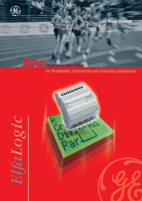
ElfaLogic<br />
<strong>GE</strong> Power Controls<br />
New Programmable Programmable Relay<br />
for Residential, Commercial and Industrial applications
A logic step in completing the range<br />
Hardware<br />
Expansion modules<br />
Digital input/output expansion modules •<br />
Analogue input expansion modules •<br />
Bus interface modules for KNX (EIB / BatiBUS / •<br />
EHS), LON and AS-i<br />
All commonly in use supply voltages •<br />
Relay or transistor outputs •<br />
Maximum configuration of one ElfaLogic CPU is •<br />
limited to 24 digital inputs, 16 digital outputs and<br />
8 analogue inputs<br />
Catalogue number structure<br />
ElfaLogic C = CPU<br />
D = CPU with display<br />
E = Expansion module<br />
B = Bus interface module<br />
S = Programming tools<br />
M = Memory module<br />
A = Application ready memory module<br />
Central processing units (CPU)<br />
• CPU’s with or without display<br />
• All commonly used supply voltages<br />
• 8 digital (on - off) inputs and 4 digital outputs<br />
• 2 analogue inputs (depending on type)<br />
• Relay or transistor outputs<br />
• Broad range of integrated ready to use functions<br />
• Automatic summer/wintertime change<br />
• Password protection<br />
• Soft-key function<br />
• Settings stored in the event of a power outage<br />
EL Subfamily DI AI DO AO OT Operating voltage<br />
Number of digital inputs 230U = 230V ac or dc<br />
Number of analogue inputs 024U = 24V ac or dc<br />
Number of digital outputs 024D = 24V dc<br />
Number of analogue outputs<br />
Output type R= <strong>relay</strong>; T= transistor
Programming tools<br />
As logic as 1 – 2 – 3 – 4 – 5<br />
1 3<br />
Drag and drop functions (symbols) from the<br />
toolbar (A) to the drawing editor area (B)<br />
A<br />
B<br />
2 4<br />
Make ‘electrical’ connections between<br />
functions (symbols) by clicking on an in- or<br />
output and dragging the ‘wire’ to an out- or<br />
input (C)<br />
C<br />
H<br />
5<br />
Adjust the parameters for Your application<br />
G<br />
E<br />
D<br />
Simulate the schematic prior to installation<br />
to assure error-free field-operation; View<br />
output- (E: lamp illuminates; F: output turns<br />
red) and wire-status (G: wire turns red) as<br />
You activate the inputs (H: input turns red)<br />
Link your PC with the ElfaLogic hardware<br />
using the ElfaLogic serial cable, and download<br />
and run the application<br />
F
CPU with display<br />
CPU without display<br />
Digital expansion modules<br />
Analogue expansion modules<br />
Bus interface modules (4)<br />
Programming Tools<br />
Accessories<br />
Basic<br />
Advanced<br />
Programmable <strong>relay</strong> - Hardware<br />
Operating voltage<br />
230Vuc<br />
24Vuc<br />
24 or 12Vdc<br />
24 or 12Vdc<br />
230Vuc<br />
24Vuc<br />
24 or 12Vdc<br />
230Vuc<br />
24Vuc<br />
24 or 12Vdc<br />
24 or 12Vdc<br />
24 or 12Vdc<br />
Interface<br />
EIB / KnX<br />
LonWorks<br />
AS-i<br />
Battery<br />
back-up<br />
80h<br />
80h<br />
80h<br />
80h<br />
80h<br />
80h<br />
80h<br />
-<br />
-<br />
-<br />
-<br />
-<br />
Operating<br />
voltage<br />
24Vuc<br />
24Vuc<br />
24Vdc<br />
Number of<br />
digital<br />
inputs<br />
(1)<br />
8<br />
8<br />
8<br />
8<br />
8<br />
8<br />
8<br />
4<br />
4<br />
4<br />
4<br />
0<br />
Number of<br />
digital<br />
inputs<br />
(5)<br />
16<br />
16<br />
4<br />
Number of<br />
analogue<br />
inputs<br />
(2)<br />
0<br />
0<br />
2<br />
2<br />
0<br />
0<br />
2<br />
0<br />
0<br />
0<br />
0<br />
2<br />
Number of<br />
analogue<br />
inputs<br />
(5)<br />
8<br />
8<br />
0<br />
Analogue<br />
input<br />
type<br />
-<br />
-<br />
0-10V<br />
0-10V<br />
-<br />
-<br />
0-10V<br />
-<br />
-<br />
-<br />
-<br />
0-10V<br />
0-20mA<br />
Number of<br />
digital<br />
outputs<br />
(5)<br />
12<br />
12<br />
4<br />
Number of<br />
digital<br />
outputs<br />
4<br />
4<br />
4<br />
4<br />
4<br />
4<br />
4<br />
4<br />
4<br />
4<br />
4<br />
0<br />
Digital<br />
output<br />
type<br />
Relay<br />
Relay<br />
Relay<br />
Transistor<br />
Relay<br />
Relay<br />
Relay<br />
Relay<br />
Relay<br />
Relay<br />
Transistor<br />
-<br />
Nominal load<br />
per output<br />
(3)<br />
10A/240V<br />
10A/240V<br />
10A/240V<br />
0,3A/24V<br />
10A/240V<br />
10A/240V<br />
10A/240V<br />
5A/240V<br />
5A/240V<br />
5A/240V<br />
0,3A/24V<br />
5A/240V<br />
Modules<br />
General remark: 230Vuc and 24Vuc devices deliverable from stock; for 24/12Vdc devices contact the sales office for availability<br />
4<br />
4<br />
4<br />
4<br />
4<br />
4<br />
4<br />
2<br />
2<br />
2<br />
2<br />
2<br />
Modules<br />
2<br />
2<br />
2<br />
Cat. No.<br />
EL D 8040R 230U<br />
EL D 8040R 024U<br />
EL D 8240R 024D<br />
EL D 8240T 024D<br />
EL C 8040R 230U<br />
EL C 8040R 024U<br />
EL C 8240R 024D<br />
EL E 4040R 230U<br />
EL E 4040R 024U<br />
EL E 4040R 024D<br />
EL E 4040T 024D<br />
EL E 0200D 024D<br />
(1) For 230V CPU's: inputs in two groups of 4; The use of the same phase within the same group is mandatory;<br />
The use of different phases is allowed only between different groups.<br />
(2) I7 and I8 on the CPU's serve or as digital or as analogue inputs.<br />
(3) For the expansion modules with <strong>relay</strong> outputs, the sum of the current passing simultaneously through all four <strong>relay</strong>s may not exceed 20A.<br />
(4) Availability: Q3 2003<br />
(5) Each remote input or output overlaps with 1 physical in/output on the ElfaLogic module.<br />
Programming tools and accessories<br />
Description<br />
Schematic design- and simulation software (Windows 95 and up, Mac OS X, Linux)<br />
Serial cable-interface for program transfer between ElfaLogic CPU and personal computer<br />
Memory module with copy protection (red)<br />
Memory module (yellow)<br />
Gang programmer (copies the contents of 1 memory module in 8 other memory modules)<br />
Pre-programmed memory modules (applications)<br />
Description<br />
From 1 to 12 impulse switches with multi-level centralized command<br />
Local, central and automatic shutters control for from 1 to 3 shutters<br />
Home comfort: timed staircase switch + timed garden lights switch + basement light switch +<br />
bathroom ventilator control<br />
Hotel room: general on/off + bathroom ventilation + bathroom quickdryer + 5 lights control +<br />
room occupied/alarm control<br />
Parking entrance and exit barrier control<br />
4-<strong>channel</strong> <strong>priority</strong> <strong>relay</strong> with cascade or cyclic operation<br />
Cat. No.<br />
EL B KNX<br />
EL B LON<br />
EL B ASI<br />
Cat. No.<br />
EL S PRG<br />
EL S CBL<br />
EL M P<br />
EL M<br />
Cat. No.<br />
EL A IS<br />
EL A SC<br />
EL A HC<br />
EL A HR<br />
EL A BC<br />
EL A PR<br />
Ref. No.<br />
666270<br />
666271<br />
666272<br />
666273<br />
666275<br />
666276<br />
666277<br />
666280<br />
666281<br />
666282<br />
666283<br />
666284<br />
Ref. No.<br />
666290<br />
666291<br />
666292<br />
Ref. No.<br />
666295<br />
666296<br />
666297<br />
666298<br />
On request<br />
Ref. No.<br />
666300<br />
666301<br />
666302<br />
666303<br />
666304<br />
666305<br />
Pack.<br />
1<br />
1<br />
1<br />
1<br />
1<br />
1<br />
1<br />
1<br />
1<br />
1<br />
1<br />
1<br />
Pack.<br />
1<br />
1<br />
1<br />
Pack.<br />
1<br />
1<br />
10<br />
10<br />
1<br />
Pack.<br />
5<br />
5<br />
5<br />
5<br />
5<br />
5
Application 1<br />
Lighting control with local and centralised command<br />
The 666300 is a pre-programmed memory module that, in combination with one Elfalogic CPU and<br />
2 Elfalogic digital expansion modules features 12 impulse switches with central and multilevel<br />
central command.<br />
CPU Digital expansion module<br />
Impuls switches<br />
+ +<br />
+<br />
Central command module<br />
Memory module<br />
26 wire-ends to be treated<br />
For clarity purposes,<br />
load-wiring has been left out.<br />
+<br />
Multi-level central<br />
command module<br />
For clarity purposes,<br />
load-wiring has been left out.<br />
22 available special functions (8 available standard functions not shown)<br />
666300<br />
+<br />
+<br />
Wiring<br />
Wiring<br />
118 wire-ends to be treated
Application 2<br />
Automatic shutters/curtains control<br />
The 666301 is a pre-programmed memory module that, in combination with one ElfaLogic CPU and one ElfaLogic<br />
digital expansion module, controls up to 3 shutters. Future development will allow the control of up to 8 shutters<br />
(One ElfaLogic and 3 digital expansion modules).<br />
Manual control<br />
• Individual control of each connected shutter/curtain<br />
by means of pushbuttons:<br />
o Brief impulse (
Application 3<br />
Hotel room control<br />
The 666303 is a pre-programmed memory module that, in combination with one ElfaLogic CPU and one ElfaLogic<br />
digital expansion module, controls all electrical appliances in a hotel room.<br />
All basic controls (for a basic room) are included in the CPU-module while additional appliances in bigger rooms<br />
and/or suites can be controlled by adding the expansion module.<br />
CPU-module<br />
Inputs<br />
• General on/off input (i.e. to be used with cardswitch)<br />
switches of all loads when de-energised,<br />
allows the operation of all loads while energised<br />
• All lights on input for housekeeper<br />
• General hotel/floor alarm: when room occupied, all<br />
lights start to flash<br />
• Impulse switch control for light 1 in bedroom<br />
• Impulse switch control for light 1 in bathroom<br />
• Delayed-on- and –of-bathroom ventilation fan<br />
• Alarm input: when activated, the room occupied<br />
lamp outside of the room starts to flash; output can<br />
also be used for distance occupied/alarm reporting<br />
• Reset alarm input<br />
Outputs<br />
• Room occupied/alarm output • Light 1 bathroom output<br />
• Light 1 bedroom output • Bathroom fan output<br />
Expansion-module<br />
Inputs<br />
• Impulse switch control for light 2 in bedroom<br />
• Impulse switch control for light 3 in bedroom<br />
• Impulse switch control for light 2 in bathroom<br />
• Off-delayed timer for bathroom IR-quick-dryer<br />
Outputs<br />
+ +<br />
666303<br />
CPU Digital expansion module Memory module<br />
• Light 2 bedroom output<br />
• Light 3 bedroom output<br />
• Light 2 bathroom output<br />
• Bathroom IR-quick-dryer output (an intermediate<br />
contactor is required to switch the load)
Ref. R/2193/E/X 8.0 12/01<br />
Copyright <strong>GE</strong> Power Controls 2002 - 680858<br />
Application 4<br />
Load shedding control (4 <strong>channel</strong> <strong>priority</strong> <strong>relay</strong>)<br />
The 666305 is a pre-programmed memory module that, plugged in to an ElfaLogic CPU, controls up to 4 loads<br />
according to a predefined <strong>priority</strong>-scheme (cascade) or in cyclic way.<br />
A multi-<strong>channel</strong> <strong>priority</strong> <strong>relay</strong> is typically used to avoid the (main) MCB to trip due to excess load by shedding the<br />
loads.<br />
Cascade operation<br />
At the start of each cycle (cycle-time is typically 7minutes<br />
but user adjustable) the <strong>priority</strong> <strong>relay</strong> searches for the<br />
optimal combination of switched-on loads, by switching<br />
off the loads with the lowest <strong>priority</strong> first, until the measured<br />
current drops below the threshold value (measured<br />
i.e. by means of the 1-<strong>channel</strong> <strong>priority</strong> <strong>relay</strong> 666445).Once<br />
the measured current has dropped below the threshold<br />
value, the <strong>priority</strong> <strong>relay</strong> stops the sequence and the loads<br />
currently switched on stay on until the next cycle starts.<br />
The sequence executed is as follows (<strong>channel</strong> 1 highest<br />
and <strong>channel</strong> 4 lowest <strong>priority</strong>)<br />
Channel 1 2 3 4<br />
ON ON ON ON<br />
ON ON ON OFF<br />
ON ON OFF ON<br />
ON ON OFF OFF<br />
ON OFF ON ON<br />
ON OFF ON OFF<br />
ON OFF OFF ON<br />
…<br />
OFF OFF OFF ON<br />
OFF OFF OFF OFF<br />
Tel. +32/9 210 38 11<br />
Fax +32/9 210 39 20<br />
E-mail: ge.gepcbel@gepc.ge.com<br />
http://www.gepowercontrols.com<br />
1 <strong>channel</strong> <strong>priority</strong> <strong>relay</strong> CPU Memory module<br />
Cyclic operation<br />
To prevent from one or more <strong>channel</strong>s to stay off systematically,<br />
the other way of operating is for each load to<br />
switch on for a certain amount of time and switch off<br />
again while the next <strong>channel</strong> is switched on. A typical<br />
application for a cyclic operation is electrical heating:<br />
all electrical heaters switched on together would trip<br />
the MCB, while in cascade set-up, the room with the<br />
least <strong>priority</strong> could stay cold forever…<br />
The sequence executed is as follows<br />
Channel 1 2 3 4<br />
ON OFF OFF OFF<br />
OFF ON OFF OFF<br />
OFF OFF ON OFF<br />
OFF OFF OFF ON<br />
<strong>GE</strong> Power Controls<br />
International Sales<br />
Guldensporenpark 30<br />
B-9820 Merelbeke (Gent)<br />
Belgium<br />
+ +<br />
666446<br />
666305<br />
<strong>GE</strong> Power Controls