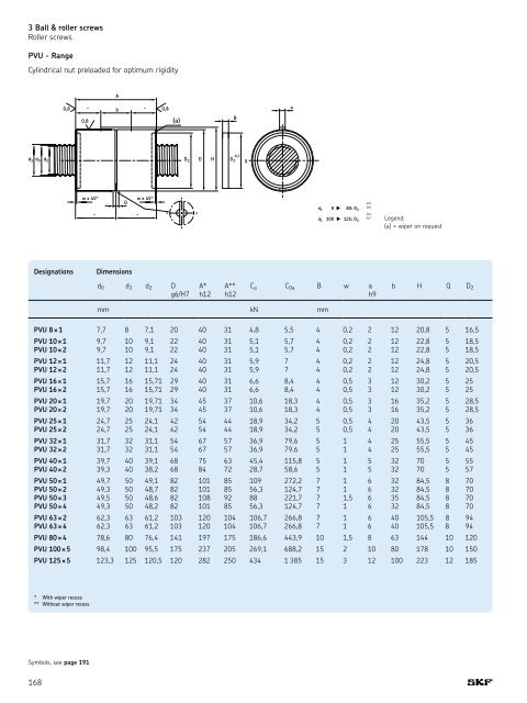
3 Ball & roller screws Roller screws PVU - <strong>Range</strong> Cylindrical nut preloaded for optimum rigidity A 0,8 " b " 0,8 B 0,8 (a) -0,3 d 1 d 0 d 2 D 2 D H D 2 g a w x 45° w x 45° Q " " -0,2 d 1 8 g 80: D -0,4 2 -0,4 d 1 100 g 125: D -0,7 2 Legend: (a) = wiper on request Designations Dimensions d 0 d 1 d 2 D g6/H7 A* h12 A** h12 C a C 0a B w a h9 b H Q D 2 mm kN mm PVU 8 ¥ 1 7,7 8 7,1 20 40 31 4,8 5,5 4 0,2 2 12 20,8 5 16,5 PVU 10 ¥ 1 9,7 10 9,1 22 40 31 5,1 5,7 4 0,2 2 12 22,8 5 18,5 PVU 10 ¥ 2 9,7 10 9,1 22 40 31 5,1 5,7 4 0,2 2 12 22,8 5 18,5 PVU 12 ¥ 1 11,7 12 11,1 24 40 31 5,9 7 4 0,2 2 12 24,8 5 20,5 PVU 12 ¥ 2 11,7 12 11,1 24 40 31 5,9 7 4 0,2 2 12 24,8 5 20,5 PVU 16 ¥ 1 15,7 16 15,71 29 40 31 6,6 8,4 4 0,5 3 12 30,2 5 25 PVU 16 ¥ 2 15,7 16 15,71 29 40 31 6,6 8,4 4 0,5 3 12 30,2 5 25 PVU 20 ¥ 1 19,7 20 19,71 34 45 37 10,6 18,3 4 0,5 3 16 35,2 5 28,5 PVU 20 ¥ 2 19,7 20 19,71 34 45 37 10,6 18,3 4 0,5 3 16 35,2 5 28,5 PVU 25 ¥ 1 24,7 25 24,1 42 54 44 18,9 34,2 5 0,5 4 20 43,5 5 36 PVU 25 ¥ 2 24,7 25 24,1 42 54 44 18,9 34,2 5 0,5 4 20 43,5 5 36 PVU 32 ¥ 1 31,7 32 31,1 54 67 57 36,9 79,6 5 1 4 25 55,5 5 45 PVU 32 ¥ 2 31,7 32 31,1 54 67 57 36,9 79,6 5 1 4 25 55,5 5 45 PVU 40 ¥ 1 39,7 40 39,1 68 75 63 45,4 115,8 5 1 5 32 70 5 55 PVU 40 ¥ 2 39,3 40 38,2 68 84 72 28,7 58,6 5 1 5 32 70 5 57 PVU 50 ¥ 1 49,7 50 49,1 82 101 85 109 272,2 7 1 6 32 84,5 8 70 PVU 50 ¥ 2 49,3 50 48,7 82 101 85 56,3 124,7 7 1 6 32 84,5 8 70 PVU 50 ¥ 3 49,5 50 48,6 82 108 92 88 221,7 7 1,5 6 35 84,5 8 70 PVU 50 ¥ 4 49,3 50 48,2 82 101 85 56,3 124,7 7 1 6 32 84,5 8 70 PVU 63 ¥ 2 62,3 63 61,2 103 120 104 106,7 266,8 7 1 6 40 105,5 8 94 PVU 63 ¥ 4 62,3 63 61,2 103 120 104 106,7 266,8 7 1 6 40 105,5 8 94 PVU 80 ¥ 4 78,6 80 76,4 141 197 175 186,6 443,9 10 1,5 8 63 144 10 120 PVU 100 ¥ 5 98,4 100 95,5 175 237 205 269,1 688,2 15 2 10 80 178 10 150 PVU 125 ¥ 5 123,3 125 120,5 120 282 250 434 1 385 15 3 12 100 223 12 185 * With wiper recess ** Without wiper recess Symbols, see page 191 168
PVK - <strong>Range</strong> Flanged nut preloaded for optimum rigidity A PVK: d 1 8 g 63 Q u (a) r A 2 A 1 0,8 r 0,8 (b) (d) J 3 (e) +0,5 d 1 d 0 d 2 D 0 D 2 D g6/H7 D 1 PVK: d 1 8 g 125 4 (e) Q u 3 G (c) (f) J Legend: (a) = wiper recess (b) = wiper on request (c) = equidistant (d) = dowel pins to hold preload (e) = bolts for transport (f) = key to hold preload Designations Dimensions Basic load ratings Preload torque Lead dynamic static d 1 P h l tp d 0 d 2 D A h12 D 1 J js12 G Q u C a C oa T pr mm [°] kN Nm PVK 8 ¥ 1 8 1 400 7,7 7,1 22 40 43 33 6 ¥ M4 M6 30 4,8 5,5 0,02 - 0,08 PVK 10 ¥ 1 10 1 500 9,7 9,1 22 40 43 33 6 ¥ M4 M6 30 5,1 5,7 0,03 - 0,10 PVK 10 ¥ 2 10 2 500 9,7 9,1 22 40 43 33 6 ¥ M4 M6 30 5,1 5,7 0,03 - 0,10 PVK 12 ¥ 1 12 1 600 11,7 11,1 25 40 46 36 6 ¥ M4 M6 30 5,9 7 0,05 - 0,15 PVK 12 ¥ 2 12 2 600 11,7 11,1 25 40 46 36 6 ¥ M4 M6 30 5,9 7 0,05 - 0,15 PVK 16 ¥ 1 16 1 825 15,7 15,1 30 40 51 41 6 ¥ M4 M6 30 6,6 8,4 0,10 - 0,20 PVK 16 ¥ 2 16 2 825 15,7 15,1 30 40 51 41 6 ¥ M4 M6 30 6,6 8,4 0,10 - 0,20 PVK 20 ¥ 1 20 1 1 050 19,7 19,1 35 45 58 46 6 ¥ M5 M6 30 10,6 18,3 0,18 - 0,32 PVK 20 ¥ 2 20 2 1 050 19,7 19,1 35 45 58 46 6 ¥ M5 M6 30 10,6 18,3 0,20 - 0,35 PVK 25 ¥ 1 25 1 1 300 24,7 24,1 45 54 68 56 6 ¥ M5 M6 30 18,9 34,2 0,35 - 0,65 PVK 25 ¥ 2 25 2 1 300 24,7 24,1 45 54 68 56 6 ¥ M5 M6 30 18,9 34,2 0,40 - 0,70 PVK 32 ¥ 1 32 1 1 700 31,7 31,1 56 67 84 70 6 ¥ M6 M6 30 36,9 79,6 0,50 - 0,95 PVK 32 ¥ 2 32 2 1 700 31,7 31,1 56 67 84 70 6 ¥ M6 M6 30 36,9 79,6 0,50 - 0,95 PVK 40 ¥ 1 40 1 2 150 39,7 39,1 68 75 102 85 6 ¥ M8 M6 30 45,4 115,8 0,70 - 1,40 PVK 40 ¥ 2 40 2 2 150 39,3 38,2 68 84 102 85 6 ¥ M8 M6 30 28,7 58,6 0,70 - 1,40 PVK 50 ¥ 1 50 1 2 800 49,7 49,1 82 101 124 102 6 ¥ M10 M6 30 109 272,2 1,20 - 2,50 PVK 50 ¥ 2 50 2 2 800 49,3 48,7 82 101 124 102 6 ¥ M10 M6 30 56,3 124,7 1,20 - 2,50 PVK 50 ¥ 3 50 3 2 800 49,5 48,6 82 108 124 102 6 ¥ M10 M6 30 88 221,7 1,20 - 2,50 PVK 50 ¥ 4 50 4 2 800 49,3 48,2 82 101 124 102 6 ¥ M10 M6 30 56,3 124,7 1,20 - 2,50 PVK 63 ¥ 2 63 2 3 600 62,3 61,2 105 120 150 127 6 ¥ M12 M8 ¥ 1 30 106,7 266,8 1,80 - 3,20 PVK 63 ¥ 4 63 4 3 600 62,3 61,2 105 120 150 127 6 ¥ M12 M8 ¥ 1 30 106,7 266,8 2,00 - 3,50 PVK 80 ¥ 4 80 4 4 000 78,6 76,4 140 197 200 170 8 ¥ M16 M8 ¥ 1 22,5 186,6 443,9 3,00 - 5,50 PVK 100 ¥ 5 100 5 4 000 98,4 95,5 180 237 240 210 10 ¥ M16 M8 ¥ 1 15 269,1 688,2 4,50 - 7,50 PVK 125 ¥ 5 125 5 4 000 123,3 120,5 220 282 310 270 12 ¥ M18 M8 ¥ 1 15 434 1 385 7,00 - 10,0 Symbols, see page 191 169
- Page 1 and 2:
Linear motion standard range
- Page 3 and 4:
58 Applications 59 LLT Profile rail
- Page 5 and 6:
Contents (by alphabetical order) A
- Page 7 and 8:
LWRE 3 ............................
- Page 9 and 10:
General 1 About SKF The SKF Group i
- Page 11 and 12:
About this publication The encyclop
- Page 13 and 14:
Linear guides 2 Fig. 1 Fig. 2 Fig.
- Page 15 and 16:
Compact series 2 LBBR Compact linea
- Page 17 and 18:
2 LQCD / LQCF Open or closed self-a
- Page 19 and 20:
Ordering key L B B R 4 -2LS/HV6 Typ
- Page 21 and 22:
LPBR .. Linear plain bearings Desig
- Page 23 and 24:
LTBR .. Tandem linear ball bearing
- Page 25 and 26:
LEBS .. Tandem shaft blocks suitabl
- Page 27 and 28:
Ordering key (Continued) L Type Bea
- Page 29 and 30:
LPAR .. Linear plain bearings witho
- Page 31 and 32:
LUCR .. PA Single plain bearing uni
- Page 33 and 34:
LVCD .. Flanged self-aligning units
- Page 35 and 36:
LTCD .. Tandem units, self-aligning
- Page 37 and 38:
LEAS .. Tandem shaft blocks, closed
- Page 39 and 40:
LBHT .. Standard series 3 Heavy-loa
- Page 41 and 42:
LUCT .. BH Single heavy load units,
- Page 43 and 44:
LTCT .. Tandem units, open type, re
- Page 45 and 46:
Precision shafts Fig. 8 SKF precisi
- Page 47 and 48:
Ordering key LJ / Type Designation
- Page 49 and 50:
ESSC 5 As ESSC 4 with two front sid
- Page 51 and 52:
Standard designs for fixed length w
- Page 53 and 54:
Linear ball bearing table without d
- Page 55 and 56:
LZBU .. A-2LS Quadro linear tables,
- Page 57 and 58:
LZAU ..-2LS Quadro linear tables, L
- Page 59 and 60:
LLT Profile rail guides The product
- Page 61 and 62:
Ordering key Type code: Carriage (c
- Page 63 and 64:
Carriage LLTHC ,, A D 2 H 1 H6 D 1
- Page 65 and 66:
W 1 S 2 Carriage LLTHC .. LA L 4 L
- Page 67 and 68:
Carriage LLTHC .. R W 1 S 2 H 4 L 4
- Page 69 and 70:
Carriage LLTHC .. LR L 4 L 1 W 1 S
- Page 71 and 72:
Carriage LLTHC .. U H 5 L 4 L 1 D 2
- Page 73 and 74:
Carriage LLTHC .. SU H 1 H6 D 2 L 1
- Page 75 and 76:
LLTHR rails E F D 2 H 1 H6 2 W D 1
- Page 77 and 78:
LLTHR .. D4 rails H 1 H7 E F 2 W S
- Page 79 and 80:
Scraper plate Scraper plate • Mat
- Page 81 and 82:
Seal kit Seal kit The seal kit cons
- Page 83 and 84:
Mounting The bellows are partly pre
- Page 85 and 86:
Miniature profile rail guides Fig.
- Page 87 and 88:
The running parallelism accuracy in
- Page 89 and 90:
LLMHR Standard rails Designations D
- Page 91 and 92:
Applications In response to our cus
- Page 93 and 94:
Precision rail guides Fig. 34 Modul
- Page 95 and 96:
Ordering key LW Type Designation ty
- Page 97 and 98:
LWR 3 / 6 .. KIT 4 rail guides LWR
- Page 99 and 100:
LWR 3 Designations Dimensions Load
- Page 101 and 102:
LWRE .. LWRE rail guides are a logi
- Page 103 and 104:
LWRE 3 / 6 .. ACS KIT 4 rail guides
- Page 105 and 106:
LWRE 6 Designations Dimensions Load
- Page 107 and 108:
LWRE 3 .. ACSM KIT 4 rail guides LW
- Page 109 and 110:
LWRE 6 ACS Designations Dimensions
- Page 111 and 112:
LWRM 6 / LWRV 6 Designations Dimens
- Page 113 and 114:
LWM 3015 / LWV 3015 Designations Di
- Page 115 and 116:
LWM 7040 / LWV 7040 Designations Di
- Page 117 and 118: LWRPM 3 / 6 / 9 Designations Dimens
- Page 119 and 120: Notes 2 119
- Page 121 and 122: Ball & roller screws Ball screws an
- Page 123 and 124: Precision rolled ball screws Fig. 9
- Page 125 and 126: Notes 3 125
- Page 127 and 128: L L 1 D 1 d 0 d 1 d 2 M 1 3 Designa
- Page 129 and 130: Accessories for SX/BX nuts FHRF Rou
- Page 131 and 132: L 8 M61 -6H long 8 22,5° †D 4 M
- Page 133 and 134: †D 4 30° 60° M 2 ,2 ,5 D 1 D 6
- Page 135 and 136: 60° 30° M 2 D 6 (6) †D 5 †IT1
- Page 137 and 138: Fig. 10 Fig. 11 3 Designations Dime
- Page 139 and 140: Standard end machining for nominal
- Page 141 and 142: Standard machining ends for nominal
- Page 143 and 144: BUF support bearing Accessories for
- Page 145 and 146: Ordering key / - WPR Nut type: Nut
- Page 147 and 148: L 8 M61 -6H long 8 22,5° †D 4 M
- Page 149 and 150: M61 -6H long 8 22,5° †D 4 L 8 D
- Page 151 and 152: A A5 A2 A3 (a) 30¡ (b) D1 d2 d0 3
- Page 153 and 154: Roller screws There are two non-com
- Page 155 and 156: Recirculating roller screws (fig. 2
- Page 157 and 158: Ordering key / Play or preload: Ax
- Page 159 and 160: SRC /BRC - Range (Continued) A 0,8
- Page 161 and 162: SRF/BRF - Range (Continued) A u (a)
- Page 163 and 164: PRU - Range (Continued) A 0,8 0,8 "
- Page 165 and 166: PRK - Range (Continued) (a) B r A 0
- Page 167: SVF/BVF - Range Flanged nuts with a
- Page 171 and 172: Fig. 27 3 Axial play The Ultra Powe
- Page 173 and 174: HRC - Range (Continued) A 0,8 " b "
- Page 175 and 176: HRF - Range (Continued) B A A 2 A 1
- Page 177 and 178: HRP - Range (Continued) lubrication
- Page 179 and 180: Inverted roller screws (figs. 23 an
- Page 181 and 182: Roller screws service range General
- Page 183 and 184: Service range option 1 Recirculatin
- Page 185 and 186: Service range option 2 Recirculatin
- Page 187 and 188: Service range option 3 Complete rec
- Page 189 and 190: End machining for FLRBU 3 Designati
- Page 191 and 192: Symbols C req N Required load ratin
- Page 193 and 194: Notes 3 193
- Page 195 and 196: Tables: driven and not driven Gener
- Page 197 and 198: Fig. 6 Fig. 7 Fig. 8 LZBB and LZAB
- Page 199 and 200: Notes 4 199
- Page 201 and 202: LZM Main dimensions for miniature s
- Page 203 and 204: Standard slides GCL, GCLA, RM Order
- Page 205 and 206: 4 Designations Dimensions Load-carr
- Page 207 and 208: 4 Designations Dimensions Load-carr
- Page 209 and 210: Slides, tables and compact cross ta
- Page 211 and 212: SSM / SSK (Continued) C2 C L1 J C1
- Page 213 and 214: Compact cross tables TO / TS 4 Desi
- Page 215 and 216: RSM / RSK (Continued) Designations
- Page 217 and 218: LZBB (On request) Linear ball beari
- Page 219 and 220:
Profile rail guide slides LTB with
- Page 221 and 222:
LTB110.L1.SD/TN12xx-SC: Slides with
- Page 223 and 224:
LTB170.L1.SD/TN16xx-SC: Slides with
- Page 225 and 226:
LTB235.L1.SX/TN/TL25xx-BL (Continue
- Page 227 and 228:
LTB235.L1.SX/TN/TL25xx-SC (Continue
- Page 229 and 230:
LTB320.L1.SX/TN/TL32xx-SC: Slides w
- Page 231 and 232:
Notes 4 231
- Page 233 and 234:
Drive: Slides with linear motor dri
- Page 235 and 236:
LTS 182.L1.1FN3-100-xK: Slides with
- Page 237 and 238:
LTS 212.L1.1FN3-150-xK ca.14 L6 L2
- Page 239 and 240:
Applications In response to our cus
- Page 241 and 242:
Customized solutions Standard plug
- Page 243 and 244:
Notes 5 243
- Page 245 and 246:
Harnessing wind power The growing i
- Page 247 and 248:
Notes 247
- Page 249 and 250:
Notes 249
- Page 252:
® SKF is a registered trademark of