
You also want an ePaper? Increase the reach of your titles
YUMPU automatically turns print PDFs into web optimized ePapers that Google loves.
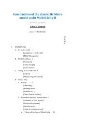
Construction of the classic Six Metre<br />
model yacht Michel Selig II<br />
By Basil Carmody (basil@sfr.fr)<br />
Table of contents<br />
[xxx] = illustration<br />
P<br />
a<br />
g<br />
e<br />
I. Michel Selig<br />
A. Six Metre yachts 1<br />
[comparison of 6mR hulls]<br />
[Third Rule equation]<br />
B. The birth of Sixes 2<br />
[Architects]<br />
[Onkel Adolph]<br />
[Louis Dyèvre]<br />
C. Falling in love with Sixes 4<br />
[Caprice]<br />
[Michel Selig in Cornwall]<br />
D. Michel Selig<br />
1. History 5<br />
[Launching]<br />
[Steering wheel]<br />
[Hebrides n = 3]<br />
[Chris White & nail rot]<br />
2. Restoration becomes reconstruction 9<br />
[Unloading at Villa Manou]<br />
[Temporarily propped]<br />
[Movable props]<br />
[Cabin & cockpit removed]<br />
a. Taking off the lines of Michel Selig 11
[JMM & masking tape]<br />
[Chevalet]<br />
- Offsets 12<br />
[Stations]<br />
[Stations & waterlines]<br />
- Two fundamental errors 15<br />
b. Condition<br />
- Lack of stiffness 16<br />
- Floors 16<br />
[Ring floor]<br />
- Nail rot 17<br />
[Nail rot from inside]<br />
[Ring floor]<br />
c. A complete re-build or a component by component<br />
replacement?<br />
19<br />
[Nirvana moulds]<br />
[Nirvana ribbands]<br />
[Nirvana frames]<br />
d. Lofting 20<br />
[Half shell]<br />
[Lofting platform]<br />
e. Abandon 22<br />
II.<br />
Michel Selig II (MS II)<br />
A. Intention 22<br />
B. Bread n' butter contruction method 23<br />
[Cardinal II]<br />
C. Lofting again<br />
1. Profile 24<br />
[Station sections]<br />
2. Stations and waterlines 25<br />
D. Calculation of the ballast 25<br />
E. Wood 26<br />
F. Fabricating the rough hull<br />
1. Transfer of waterlines to the planks
a. Slaloming through the knots 26<br />
b. Drawing the waterlines on the planks 26<br />
[Top and bottom of plans with red and green lines]<br />
2. Half lifts<br />
a. Cutting the half lifts 27<br />
b. Preview of the finished hull 27<br />
[Cumulative build up of lifts]<br />
c. Drawing stations on the sides the "half" lifts 30<br />
[Drawing the station lines on the sides of a half lift]<br />
[Stacking the lifts]<br />
[Alignment of the station lines]<br />
3. Knots 31<br />
[Two bits]<br />
[Keyhole guide]<br />
[Nail points]<br />
[Bungs in place]<br />
4. Gluing the half lifts together 33<br />
[Close up of gluing the forward part]<br />
[Close up of gluing the aft part]<br />
[Overall view from the bow]<br />
[Overall view from the stern]<br />
5. Upper part of the hull 36<br />
[Gluing the two lowest lifts together]<br />
[Gluing the two top lifts together]<br />
[Exterior bridges]<br />
[Upper hull]<br />
[Interior bridges]<br />
[Bottom of the studs]<br />
[Stud supports]<br />
[Complete rough hull]<br />
6. Plugs and sternpost 38<br />
7. Full rough hull 39<br />
I. Michel Selig I
A. Six Metre yachts<br />
Six Metre yachts are built according to the International Rule<br />
which was first drafted in 1907. They are among the most<br />
beautiful yachts in existence, with long forward and aft<br />
overhangs. They are referred to as "Sixes" or "6mR's".<br />
A comparison of 6mR hulls. The top boat is the 1985<br />
"Capriccio". The 2nd the 1930 Totem and the bottom<br />
one the 1938 Goose, perhaps the most successful Six of<br />
all times.<br />
A rule is different from a class. The hulls of boats of the same<br />
class are all identical (more or less).<br />
A rule is an equation which specifies the relationship between<br />
various parameters of a boat, with a number as the solution of<br />
the equation. The current equation for the International Rule is:<br />
where:<br />
L = the overall length
d = a measurement of how much the hull has a<br />
"wine glass" shape<br />
F = the freeboard<br />
S = the sail area<br />
The International Rule also includes Eights, Twelves and even<br />
higher. The numbers of their names correspond to the solution<br />
of the equation. If the equation gives a result less than 6, it will<br />
qualify as a Six . Ditto for the other names.<br />
B. The birth of Sixes<br />
1907 was at the highpoint of the first worldwide globalisation<br />
period. It ended with WW I.<br />
This globalisation also extended to yachtsmen of various<br />
European countries who wanted to race against each other with<br />
equivalent boats. The Rule permitted naval architects of these<br />
countries to come up with their best designs for boats whose<br />
parameters conformed to the Rule. In each country, yachtsman<br />
commissioned boats from these architects and then raced them<br />
in international competitions. The best architects were:<br />
William Fife (UK)<br />
Johan Anker<br />
(Norway)<br />
Torre Holm<br />
(Sweden)<br />
Gustav Estlander<br />
(Finland)<br />
Olin Stephens (USA)<br />
The first international race of Sixes was sailed in 1907 on the<br />
Seine River in France at Meulan, organised by the Cercle de<br />
Voile de Paris. When the current was too strong, the boats<br />
anchored. They also ran aground on the mud flats. It was won<br />
by the German entry, Onkel Adolph, pictured below:
The class (the word is applied to Sixes) prospered. 1000 boats<br />
were built before WWII. It became an Olympic class and it was<br />
"the" development class. New ideas were first tried out on<br />
Sixes.<br />
An anomaly of the Rule is that the boats are twice as long as<br />
their numbers. A Six is about 12 m. long.<br />
This goes back to a humourous story at the London conference<br />
that created the Rule in 1907. In fact the conference was fixed.<br />
The northern countries and the U.K. had already decided the<br />
form of the equation.<br />
The monolingual French representative, Louis Dyèvre, wasn't in<br />
on the "fix".<br />
He huffed and puffed in French at the blackboard advocating a<br />
variant of the American Universal Rule which has a parameter<br />
in the denominator.
As a sop, the conference included a useless denominator to the<br />
equation with a value of about 2 (see above). As a result, this<br />
has the effect of dividing the overall length of a Six by 2,which<br />
is why a boat which is about12 m. long is called a Six.<br />
C. Falling in love with Sixes<br />
We have a summer house at Saint-Tropez, France. It's over a<br />
century old and it was tiny when we bought it (less that 500 sq.<br />
ft.)<br />
After the general contractor walked off the job after a year, I<br />
took over. During this time, I came to love Saint-Tropez during<br />
the winter.<br />
When the house was finally finished, I wondered what I could<br />
do to justify coming to Saint-Tropez during the winter instead of<br />
staying in Paris.<br />
By chance I saw a Six, GBR 48 Caprice<br />
The 1946 Six "Caprice" designed and built by<br />
McGruer & Son of Clynder, Scotland
and fell in love with the class. I then decided to look for a<br />
wreck of a Six, which I soon found in Cornwall, which I could<br />
restore in our garden in Saint-Tropez. She was K 75 Joanna, ex-<br />
G 24 Michel Selig and Avalun VIII.<br />
D. Michel Selig<br />
1. History<br />
Michel Selig at the Ocean Yacht Co. boatyard in<br />
Cornwall at the time of purchase<br />
First her name: G 24 Michel Selig, G 24 being her sail<br />
number.. It remains an unknown. Literally, it means<br />
Michael the Blessed. No German speaker I've met has<br />
come up with an explanation.<br />
She was commissioned by Hans Collignon, a prosperous<br />
printer and active yachtsman who sailed on the Wannsee, a<br />
lake on the outskirts of Berlin. He intended to enter her in<br />
the June 1936 German elimination trials for the upcoming<br />
Olympic Games, whose sailing activities were located at<br />
Kiel, just to the east of Denmark.<br />
For some unknown reason, he commissioned Reinhard<br />
Drewitz, probably the world's best designer of sailing<br />
dinghies of the period, as architect. Drewitz must have told<br />
Colllignon that he was no match for successful 6mR<br />
architects like Anker, etc. (see above). He may have<br />
convinced Collignon to make a bet on the weather.<br />
The Berlin boatyard of Wilhelm Buchholz built her. She is<br />
the only Berlin built Six.<br />
In June, the weather in Kiel is usually quite windy. There is<br />
a 10% chance that the Scandinavian high will descend to<br />
Kiel bringing calm breezes. Drewitz may have said that he<br />
could design a Six optimized for low wind speeds and thus<br />
perhaps faster than the other Sixes with their general<br />
purpose all weather design.<br />
His design was a Six that resembled a centreboard sailing<br />
dinghy. In the formula of the International Rule above, the<br />
variable "d" corresponds to a penalty for having a wineglass<br />
shaped cross section, rather than a rounded one. Drewitz's<br />
centreboard shape resulted in a severe penalty. To<br />
compensate for it, he designed the boat to float bow down,
almost exposing the rudder, to lower the waterline length<br />
which compensated the "d" penalty.<br />
Two key opposing concepts in sailboat design are wetted<br />
surface and hull speed In light winds, one wants a<br />
minimum of wetted surface. For stronger winds, when the<br />
boat reaches full speed, it reaches a limit based on its<br />
waterline length (its hull speed). The longer the waterline<br />
length, the faster the hull speed.<br />
Drewitz designed such a light boat that, if the crew moved<br />
forward, the boat tilted forward and its wetted surface was<br />
reduced and, if it moved aft, the boat tilted aft, extending its<br />
waterline length. It was a remarkable concept for the<br />
period. It is now common practice for certain modern<br />
racing yachts.<br />
Apparently, Collignon rejected the concept after the boat<br />
was built. To make her float "normally, he had 120 kg. of<br />
the forward part of the ballast moved aft in the form of forty<br />
3 kg. lead ingots, thereby also rendering her rating so that<br />
she was no longer a Six.<br />
Photo of Michel Selig before launching. The caption in<br />
German explains Drewitz's concept of shifting the<br />
crew's weight forward and aft, but the boat had<br />
already been "adjusted" by Collignon to give it a
"normal" waterline. (Note the "wine glass" cross<br />
section.)<br />
He sold her, bought a second hand Six for the Olympic<br />
trials and was eliminated. Her new owner, Dr Tubiak,<br />
named her G 24 Avalun VIII, sailing her at Collignon's<br />
yacht club, the Verein Seglerhaus am Wannsee<br />
The Scandinavian high didn't descend on Kiel in June. It<br />
also turned out that no one was able to get Michel Selig to<br />
sail fast. (Previously, a dinghy owner had complained to<br />
Drewitz that his Drewitz designed boat was too slow.<br />
Drewitz took it over and raced it for the rest of the season,<br />
winning almost every race.)<br />
By 1939, she was in England, renamed K 75 Joanna. In the<br />
1960's she was modified as a cruiser with a steering wheel!<br />
Joanna at Tobermory equiped with a steering wheel<br />
and a two cycle Sea Gull outboard<br />
For the period 1970 - 1984, she sailed in the Hebrides.
Michel Selig, then named K 75 Joanna, in the Hebrides<br />
Her owners, a syndicate of young yachtsmen, loved her.<br />
By the 1990's, she was in need of a restoration. She had<br />
several owners, each intending to restore her and then<br />
giving up<br />
Chris White, one of the syndicate members, and his<br />
son with Joanna at the start of her restoration period.<br />
Note the black spots on the hull. More about them<br />
below.<br />
An interesting sidelight of her history is what became of her<br />
plans. Drewitz bequeathed his practice to Helmut<br />
Ruhrdanz. After the Soviet occupation, Ruhrdanz was in
East Berlin. His son needing medicine only available in<br />
West Berlin, he was allowed to go back and forth.<br />
One evening as he was entertaining three young East<br />
Berliners, they told him of their plans to cross over to the<br />
West via a tunnel. They were caught and mentioned their<br />
conversation with Ruhrdanz to the Stasi secret police. The<br />
The Stasi arrested and imprisoned Ruhrdanz and, in the<br />
process, confiscated all of Drewitz plans, presumably<br />
including the only copy of those of Michel Selig.<br />
2. Restoration becomes reconstruction<br />
As mentioned above, friends found Michel Selig for me in<br />
Cornwall. I had her shipped to Saint-Tropez sight unseen.<br />
Michel Selig arriving at our house in Saint-Tropez<br />
Propped up preliminarily. Note the prevalence of the<br />
black spots
Shored up with movable props<br />
After removal of the cabin and self bailing cockpit<br />
added when converted to cruising
2. Restoration becomes reconstruction<br />
a. Taking off the lines<br />
One of the first tasks in restoration of Michel Selig was<br />
to create a set of plans for her. I knew that the hull was<br />
sufficiently twisted that the distance from the port and<br />
starboard sides of the hull to the centreline would not<br />
be the same because of this<br />
The first step in doing this was to "take off her lines",<br />
i.e. measure enough points on the surface of the hull to<br />
be able to produce a three dimensional model, of the<br />
hull.<br />
With my gardener, we measured 800 points on the hull<br />
along the waterlines, the stations and the but<strong>toc</strong>ks<br />
(longitudinal sections) - both port and starboard.<br />
My gardener establishing the reference design<br />
waterline on the hull
Establishing reference verticals at a station. An offset<br />
was the distance between a vertical and the hull.<br />
Despite the appearance of the photo, the verticals were<br />
truly vertical.<br />
- Offsets<br />
In preparing the design of a boat, a naval architect<br />
first defines a side view of a boat (its "profile").
A drawing of the profile of Michel Selig with detail of<br />
the components of the backbone, which is thus more<br />
properly called a construction plan.<br />
He then draws a number of equally spaced vertical<br />
lines on the profile (the"stations") which represent<br />
vertical sections of the hull.<br />
Similarly, he does the same thing horizontally (the<br />
"waterlines") which represent horizontal sections of<br />
the hull.<br />
Three views of Michel Selig: 1.) upper left - the station<br />
profiles, viewed from the stern, are superposed, 2.)<br />
upper right - ditto, but viewed from the bow, 3.) the<br />
waterlines of the starboard half of the boat, viewed<br />
from the bottom, are superposed.<br />
The results remain a two dimensional representation<br />
of the hull. One can combine the stations and
waterlines on a profile view, thus creating<br />
intersections of the stations and waterlines.<br />
To add a third dimension of the hull, the architect<br />
defines a plane which cuts the hull longitudinally<br />
(the "centre plane"). (The waterlines shown above<br />
are drawn reative to the centre plane.) He then<br />
defines the distance between the centre plane and<br />
each intersection of a waterline and a station. This<br />
distance is called an "offset". Once he has done this<br />
for each intersection, he has in effect defined the<br />
hull in three dimensions. The set of these offsets is<br />
called a "table of offsets".<br />
Our 800 points were in effect a table of offsets for<br />
both the port and starboard sides.<br />
- Two fundamental errors<br />
My architect should have told me to immediately<br />
convert the take off data into a set of plans and a<br />
table of offsets. This would have led to the<br />
discovery of the inevitable errors in our<br />
measurements which could then have been corrected<br />
by re-measuring the erroneous data.<br />
He didn't and I merely set the take off data aside.<br />
I also didn't record rigourously precise data defining<br />
the profile of the boat. This would haunt me later<br />
b. Condition<br />
- Lack of stiffness<br />
The condition of the hull was abdominal. I could<br />
move the transom 20 cm. to the left and right. The<br />
ballast keel had been removed. Planks were<br />
missing. The wooden keel and the deadwood below<br />
all seemed rotten.<br />
- Floors<br />
When a boat heels, the ballast keel would like to stay<br />
in a vertical position, thus separating itself from the<br />
hull.<br />
"Floors" are used to counteract this force. They are<br />
metallic. They are firmly attached to the ballast keel<br />
and then they extend upward alongside the inside of<br />
the hull distributing the force of the ballast keel on<br />
the hull.<br />
Between the wooden keel and the ballast keel, there<br />
were a number of shims which adjusted for the<br />
difference in the angles of the two. These are called<br />
"deadwoods".
As was customary for the period, and especially for<br />
fresh water sailing, Wilhelm Buchholz had used soft<br />
steel for the floors and also for all the bolts attaching<br />
the floors and deadwoods to the hull..<br />
In saltwater, the "through hull" steel bolts attaching<br />
the floors to the hull had begun to electrolise.<br />
Similarly, many parts of the floors in the bilge had<br />
rusted away.<br />
"Ring"floor completely rusted at the bottom where it<br />
was in the bilge<br />
- Nail rot<br />
Two photos above showed the black spots on the<br />
exterior of the planking.<br />
All the black spots corresponded to "through hull"<br />
steel bolts attaching the floors to the hull. Seen from<br />
the inside of the hull, the wood around the bolt was<br />
completely rotten. The floor could be removed by<br />
simply pulling it away.
Holes of rotten wood where the floors were attached to<br />
the hull (between 17 & 18 and between 19 & 20<br />
This is a fairly unusual phenomenon called "nail rot"<br />
where the electrolysis of the bolt causes the<br />
surrounding wood to rot. It occurs on some Sixes,<br />
but never to this extent.<br />
In Michel Selig's case, the nail rot had attacked<br />
every plank and also the wooden keel and the<br />
deadwoods.<br />
I don't know why this occurred to this extent.<br />
Perhaps the steel used by Wilhelm Buchholz<br />
favoured nail rot.<br />
I also don't understand why my own architect and<br />
other architects who examined Michel Selig, never<br />
explained the nail rot situation to me. I wonder if<br />
the seller of Michel Selig, a professional yacht<br />
restorer with whom I even developed a friendship,<br />
knew, but decided to take advantage of me.
I could only conclude that almost every components<br />
of Michel Selig was rotten. The task I faced was not<br />
to restore, but to re-build completely.<br />
- A complete re-build or a component by component<br />
replacement?<br />
Given my age and my health, I knew that I would<br />
never be able to constru20ct a new Michel Selig.<br />
The approach of replacing individual components of<br />
a deformed hull seemed unwise and extremely time<br />
consuming for a mediocre finished product. I<br />
therefore chose a complete re-build, hoping that I<br />
would advance sufficiently to motivate a successor<br />
to finish the re-build.<br />
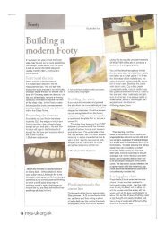
In building a Six, one usually works on the hull<br />
upside down.<br />
The planking is the fourth layer of the construction<br />
process. The layers are:<br />
-a set of vertical "moulds" which establish the shape<br />
of the hull:<br />
Moulds of the 2011 replica of the Six "Nirvana" (or<br />
"Seasta") designed by Olin Stephaens and built by<br />
Yachtwerft Robbe & Berking Classics GmbH &<br />
Co.KG of Germany<br />
- a set of horizontal "ribbands" which create the form<br />
of the boat:
Ribbands of Nirvana<br />
- the vertical "frames or "timbers which are steamed to<br />
the point of being pliable and then attached to the<br />
ribbands:<br />
Frames cooled and hardened after being attached to<br />
the ribbands<br />
- and finally the planks which are usually attached<br />
to the frames by rivets.<br />
I hoped toget to the point of creating the moulds which<br />
would have permitted my successor to set them up and<br />
proceed to the following stages.<br />
d. Lofting<br />
The sequences of steps for producing the moulds<br />
are:<br />
- taking off the lines of the hull (discussed above)<br />
- drawing the plans of the hull<br />
- lofting or laying off: drawing the plans on a 1:1<br />
scale,
- cutting the moulds from the full size plan.<br />
When I started the reconstruction phase of Michel<br />
Selig, the first step was to lay off her plans full size<br />
so as to be able to fabricate the "moulds" over which<br />
the hull would be built. I had decided to sidestep,<br />
the drawing the plans.<br />
This included the construction of a "drawing board"<br />
slightly bigger than the size of Michel Selig.<br />
Because of a lack of space and because I was setting<br />
off to re-construct Michel Selig, I dismantled her,<br />
saving every component.<br />
Michel Selig partially dismantled<br />
Next, I built the full size "drawing board" or lofting<br />
platform.
Lofting platform for laying off the lines of Michel Selig<br />
at a 1:1 scale<br />
e. Abandon<br />
As I started lofting , I encountered the errors introduced<br />
at the time of taking off her lines. The major problem<br />
was that I was unable to fit the wooden keel within the<br />
profile.<br />
To analyse the problem, I entered my data into<br />
AutoCAD. There was no solution, I would have to<br />
shorten the wooden keel.<br />
It was at this point that my age and health caught up<br />
with me. The lofting process probably required<br />
kneeling down and then getting up again over a<br />
thousand times. My knees weren't up to it, so I had no<br />
choice but to totally abandon the project.<br />
It was one of the saddest events of my life. Not that I<br />
had spent so much time arriving at that point, but that<br />
wouldn't leave a usable trace of Michel Selig for<br />
posterity.<br />
II.<br />
Michel Selig II (MS II)<br />
A. Intention<br />
Since I was unable to finish a full sized version of Michel Selig,<br />
I wanted to leave a physical model (Michel Selig II, referred to<br />
as MS II hereafter) of her for posterity.<br />
With luck, I discovered the Six Metre Class - Model Yacht<br />
Association in England which counts over 80 yachts (referred to
as R6M's), most of which are "moderns" as opposed to<br />
"classics". Michel Selig is a "classic", so MS II will be also.<br />
The association has its own Rule which is virtually identical to<br />
the International Rule and ten times more readable.<br />
The scale of the model yachts is 2/3" for each foot of a Six or a<br />
multiplier of 0.139.<br />
The yachts are radio controlled.<br />
Three of its members were extremely helpful:<br />
- Mike Ewart, president of the class, who encouraged me<br />
every bit of the way and who guided me to the two key<br />
counselors, without whom I could not have built the<br />
model.<br />
- Henry Farley, the official measurer of the class, who<br />
has measured over 80 model yachts. He was extremely<br />
helpful for all the quantitative aspects of planning and<br />
building the model.<br />
- Cliff Grove, one of the top builders of model yachts in<br />
the world. Our ample e-mail correspondence led to a<br />
genuine friendship. He helped me with all the details<br />
of actually constructing the model.<br />
When finished, I hope to donate the model and its plans and<br />
offsets to a maritime museum so that Michael Selig can continue<br />
to live after I'm gone. (I'm now 79.)<br />
The finished boat would measure 1415 mm overall with a mast<br />
of 1806 mm.<br />
B. Bread n' butter construction method<br />
There are two principal ways to build a model boat:<br />
- the "planking" method which approximates that of<br />
building a full size boat with frames and planking<br />
- the "dugout" method which resembles the construction<br />
of a dugout canoe, starting with a single piece of wood<br />
and then emptying the inside and carving the outside<br />
At age 12, as a summer camp project, I had already used the<br />
dugout method, starting from a single piece of redwood.
Cardinal II, built by the author at age 12 as a summer<br />
camp project (restored by his son, Nathaniel)<br />
A variant of the dugout method is the Bread 'n Butter method. It<br />
consists of slicing the boat horizontally into a stack of planks cut<br />
to the waterlines. Each slice (a "lift") can be cut to the outline of<br />
the waterline at the eventual thickness of the hull. This enables<br />
the use of a band saw to cut away all the excess wood both<br />
outside and inside the intended hull thickness.<br />
It was this method used for Michel Seling II.<br />
C. Lofting again<br />
1. Profile<br />
The profile was the first priority. It permitted the<br />
calculation of the position of the beginning and end of each<br />
waterline. Similarly, it provided the values for the bottom<br />
ends of the stations.<br />
The profile plan permitted me to draw the bottom ends of<br />
the stations on each cross-section of the sections plan
2. Stations and waterlines<br />
Station profiles for stations 15 - 20<br />
First, each station and waterline was drawn separately to<br />
ensure a smooth line. Next they were drawn together, as<br />
per the finished product of a naval architect, to make sure<br />
that they were correctly separated, one from the other.<br />
A table of offsets was prepared from these drawings<br />
D. Calculation of the ballast<br />
I wanted MS II to float on the same lines as Michel Selig. In<br />
fact, this was necessary for MS II to conform to the Rule.<br />
Henry Farley said that the only way to determine the weight and<br />
position of the lead ballast would be through trial and error. He<br />
advised me to build the lower portion of the hull (the "plug")<br />
detached from the upper portion - and also to build several<br />
copies of it for the trial and error process. The plug would be<br />
connected to the upper portion of the hull by two lengths of<br />
threaded s<strong>toc</strong>k which would also connect the ballast keel to the<br />
hull.<br />
In fact, the plug didn't run fully aft. I fabricated a fixed<br />
sternpost for the after portion. This would permit me to build<br />
the rudder and its radio control independently of the task of<br />
fabricating the plug..<br />
E. Wood
I wanted a light wood which would be relatively easy to carve.<br />
Western red cedar was my preference, but its price at the saw<br />
mill near Saint-Tropez was prohibitive. I settled for a spruce<br />
(Picea abies) which has an average of one or two big knots for<br />
every 1.5 metres.<br />
The saw mill didn't want to plane the planks to the spacing of<br />
the waterlines (13.9 mm. or about half an inch). I settled for the<br />
thickness of two waterlines (27.8 mm. or about 1-1/8").<br />
Separate planks were used for the starboard and port halves of<br />
lift. This allowed cutting the inside portion of the lifts with a<br />
band saw.<br />
F. Fabricating the rough hull<br />
1. Transfer of the waterlines to the planks<br />
Whereas the margin of error in drawing the plans was ± 1<br />
mm., that for working on the wood was of at least ± 2 mm.<br />
a<br />
Slaloming through the knots<br />
The first task was to find a path on each plank which<br />
avoided knots. To say the least, it was tedious.<br />
For a given plank, the upper and lower waterlines lines<br />
of the lift form a pair, which can be named by the upper<br />
waterline. There are four possible positions of the<br />
upper waterline relative to the two faces of the plank:<br />
- on the topside of the plank, the centreline of the<br />
upper waterline can be on the right or left edges<br />
of the planks<br />
- ditto for the underside of the plank.<br />
For each position, one can slide the waterline from one<br />
end to the other of the plank looking for a point where<br />
the upper waterline doesn't pass through a knot.<br />
One must next verify that the lower waterline also<br />
avoids knots.<br />
To do this, I produced lengths of cardboard with the<br />
upper and lower waterlines drawn on them. I cut it<br />
along the upper waterline and then slid both cardboard<br />
halves from one end to the other of the plank to find the<br />
best position<br />
I cut then cut the cardboard along the lower waterline<br />
and verified that the position chosen for the upper<br />
waterline also proved a knot free path for the lower<br />
one.<br />
b. Drawing the waterlines on the planks.<br />
I then drew stations on both sides of the plank<br />
corresponding to the correct position of the waterlines.
On the upper side of the plank, I drew a "safety margin"<br />
line 3 mm. outside the waterline. This was the line<br />
used for cutting.<br />
On the lower side of the plank I did essentially the<br />
same thing: 6 mm. for the thickness of the hull, plus 3<br />
mm. as the safety margin.<br />
The top side of the lift that goes from waterline 11 to<br />
13. One can see the waterline (green) and the 3 mm.<br />
safety margin. The extreme width of the plank<br />
indicates that the hull is almost flat between these<br />
waterline.<br />
The bottom side of the same lift that goes from<br />
waterline 11 to 13. The distance between the green and<br />
red lines on the bottom of a lift is 9 mm. : 6 mm. for the<br />
thickness of the hull and a 3 mm. safety margin.<br />
2. Half lifts<br />
a. Cutting the half lifts<br />
Since I can't use electric cutting tools because of the<br />
anti-coagulants I take, I subcontracted the cutting of the<br />
lifts to my old friend and ship's carpenter, Manu<br />
Allibert of Saint Tropez. He found the planks well<br />
prepared and cut the lifts with his band saw, working<br />
for a total of five hours.<br />
b. Preview of the finished rough hull
The photos below show the cumulative stacking of the<br />
seven pairs of half lifts, starting from the highest lift to<br />
the full boat. In the next to last photo, one sees the four<br />
lifts of the plug and sternpost stacked on the lowest lift.
The two half lifts of lift no. 1 The four half lifts of lifts nos. 1 & 2<br />
The six half lifts of lifts nos. 1, 2 & 3<br />
The eight half lifts of lifts nos. 1, 2, 3<br />
& 4<br />
The ten half lifts of lifts nos. 1, 2, 3, 4<br />
& 5<br />
The four lifts of the plug and the<br />
sternpost<br />
The complete hull consisting of<br />
fourteen half lifts of lifts nos. 1 - 7,<br />
plus the four lifts of the plug and of
the sternpost<br />
c. Drawing station lines on the sides of the "half" lifts<br />
In preparing the plans for cutting, station lines had been<br />
drawn on the top and bottom of the lifts. During the<br />
carving phase, station lines are needed on the outer and<br />
inner sides of the boat.<br />
This meant connecting the station lines on the top of a<br />
half lift with those on the bottom. Disappointingly, the<br />
lines rarely lined up completely. There was usually a<br />
discrepancy of 1 - 2 mm. - and sometimes much more.<br />
This led to drawing lines of three colours:<br />
- blue: for the initial linking of the top and bottom<br />
lines, i.e. one half lift at a time,<br />
- green: for resolving discrepancies between the blue<br />
lines on both the inner and outer sides of the two<br />
halves of the lift, i.e. two half lifts at a time,<br />
- red: for defining a definitive station line on the<br />
outside of the hull over all the lifts (after gluing the<br />
lifts together).<br />
Drawing the station lines on the sides of a half lift.<br />
They should correspond to the station lines on the top<br />
and bottom of the lifts. One can see that they don't.<br />
The square ensures that the lines will be<br />
perpendicular.<br />
The next step was to verify that the station lines of the<br />
two half lifts are in alignment.
3. Knots<br />
The alignment of the station lines on the sides of the<br />
four lifts of the plug are being verified. Thrre are<br />
discrepancies.<br />
Despite slaloming among the knots in drawing the<br />
waterlines, some half lifts ended up with knots. For these, it<br />
was necessary to drill out the knots and fill them with<br />
bungs.<br />
I found that a 19 mm keyhole saw could cut out a bung to<br />
fit into a knot drilled with a 16 mm. drill.<br />
The two bits used to drill through knots and then<br />
fabricate a bung. The 16 mm. drill removes the knot.<br />
The 19 mm. keyhole saw produces a bung which will fit<br />
tightly in the hole drilled.<br />
A keyhole saw bit has a drill in the centre to guide it. The<br />
bungs needed to be solid throughout, so it was necessary to
emove the drill from the bit. Normally, this results in the<br />
bit skidding on the wood before it starts cutting.<br />
To avoid the skidding, I used a guide - and I also drove nails<br />
through the guide with the points sticking out to avoid<br />
skidding<br />
The keyhole saw bit guide (centre). The other holes were<br />
drilled in attempts to find the right combination of keyhole<br />
bit and drill bit.<br />
The nail points sticking out of the keyhole guide to<br />
avoid skidding<br />
It was important to line of the grain of the bungs with that<br />
of the half lift.
The bungs and the rest of the hull were glued with<br />
polyurethane glue. In France, it is considered carcinogenic.<br />
It is no longer available to non professionals. Accordingly,<br />
I had to buy 5 litres at an exorbitant cost.<br />
The bungs glued in place and lined up with the grain of<br />
the half lift.<br />
4. Gluing the half lifts together<br />
In gluing to half lifts together, I lined up the station lines<br />
and held the half lifts snugly one against the other and in the<br />
same plane, securing them with clamps.<br />
The first point to remember is that polyurethane sticks to<br />
everything except polyethylene. I covered my work board<br />
with a sheet of polyethylene and I wrapped the parts being<br />
glued in what is called in the U.S. "Saran Wrap", a light<br />
polyethylene film for the kitchen used to cover food<br />
It was necessary to insert nails just forward and just aft of<br />
the wedges to prevent them sliding along the hull as I<br />
tightened the clamps.
Gluing the forward part of two half lifts together. One<br />
can see the Saran wrap around the part being glued.<br />
Its purpose is to avoid adhesion to the wedges. One<br />
can also see two nails which prevent the wedges from<br />
sliding forward under the pressure of the clamp.<br />
Gluing the aft part of two half lifts together. One can<br />
see two nails at the aft end of the lift. Their purpose is<br />
to avoid the entire lift sliding aft under the pressure of<br />
the clamp and wedges at the forward end.
Forward view of two pairs of half lifts being glued<br />
together. One can see the nails blocking the wedges.<br />
Note the use of a mason's clamp for the wide part of<br />
the lift
Aft view of two pairs of half lifts being glued together.<br />
One can see the nails blocking the wedges.<br />
5. Upper part of the hull<br />
The upper part of hull consists of the seven lifts glued<br />
together.<br />
Gluing the two lowest lifts together<br />
My collection of wood clamps was insufficient for gluing<br />
together the upper lifts, which are the longest, using them<br />
alone. I had recourse to 3 kg. lead ingots and masons'<br />
clamps.<br />
For the ingots to squeeze correctly, it was necessary to place<br />
a support under the lifts where the ingots were placed.<br />
Before clamping, I placed the ingots in place. Their weight<br />
stabilised the structure, preventing it from shifting as I<br />
placed the clamps.<br />
The centre of gravity of the masons' clamps is not in line<br />
with where the pressure is being applied to the lifts. This<br />
gives them the tendency rotate out of the vertical, thus<br />
placing a twisting force on the lifts. To avoid this, they<br />
were placed next to the lead ingots which helped the lifts<br />
resist the twisting force<br />
Gluing the two top lifts together. Note<br />
the lead ingots and the masons' clamps.<br />
As the upper part of the hull narrowed, it was no longer<br />
possible to place the clamps directly on the lifts. Bridges
were necessary. According to the need, some were placed<br />
outside the hull and others inside the hull.<br />
The narrower width of the top lift, with respect to the two<br />
below, makes it impossible to place the clamps directly on it.<br />
The solution is to use a "bridge" which spans the top lift and<br />
then to put the clamps on the bridge.<br />
Fulll upper hull being glued. The bottom ends of the clamps<br />
are shown in the following photo
The use of bridges on the inside of the hull where one sees<br />
the bottom ends of the clamps of the previous icture<br />
6. Plugs and sternpost<br />
The plugs, the sternpost and the lowest lift were drilled<br />
vertically for four pieces of threaded s<strong>toc</strong>k (studs).<br />
Holes were drilled in the aft part of lift 1 of the plug to<br />
lighten it. Given the uncertainty as to the eventual position<br />
of the ballast, no other holes were drilled in the lower lifts.<br />
The lifts of the sternpost and one of the three plug were<br />
glued together.<br />
Four temporary "bridges" were placed in the upper hull to<br />
anchor the studs, thus allowing the plug and the sternpost to<br />
be attached to the upper hull.<br />
The bottom of the four studs permitting the removal of<br />
the plug from the upper hull<br />
7. The full rough hull
Temporary supports on the inside of the upper hull<br />
permitting the attachment of the plug studs<br />
Complete hull with the upper hull, the plug and the<br />
sternpost, the latter two attached to the upper hull by<br />
the studs