Michel Selig II
The Construction of The Classic Six Metre Model Yacht Michel Selig II
The Construction of The Classic Six Metre Model Yacht Michel Selig II

You also want an ePaper? Increase the reach of your titles
YUMPU automatically turns print PDFs into web optimized ePapers that Google loves.
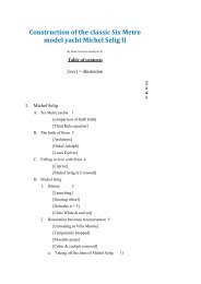
Construction of the classic Six Metre<br />
model yacht <strong>Michel</strong> <strong>Selig</strong> <strong>II</strong><br />
By Basil Carmody (basil@sfr.fr)<br />
Table of contents<br />
[xxx] = illustration<br />
P<br />
a<br />
g<br />
e<br />
I. <strong>Michel</strong> <strong>Selig</strong><br />
A. Six Metre yachts 1<br />
[comparison of 6mR hulls]<br />
[Third Rule equation]<br />
B. The birth of Sixes 2<br />
[Architects]<br />
[Onkel Adolph]<br />
[Louis Dyèvre]<br />
C. Falling in love with Sixes 4<br />
[Caprice]<br />
[<strong>Michel</strong> <strong>Selig</strong> in Cornwall]<br />
D. <strong>Michel</strong> <strong>Selig</strong><br />
1. History 5<br />
[Launching]<br />
[Steering wheel]<br />
[Hebrides n = 3]<br />
[Chris White & nail rot]<br />
2. Restoration becomes reconstruction 9<br />
[Unloading at Villa Manou]<br />
[Temporarily propped]<br />
[Movable props]<br />
[Cabin & cockpit removed]<br />
a. Taking off the lines of <strong>Michel</strong> <strong>Selig</strong> 11
[JMM & masking tape]<br />
[Chevalet]<br />
- Offsets 12<br />
[Stations]<br />
[Stations & waterlines]<br />
- Two fundamental errors 15<br />
b. Condition<br />
- Lack of stiffness 16<br />
- Floors 16<br />
[Ring floor]<br />
- Nail rot 17<br />
[Nail rot from inside]<br />
[Ring floor]<br />
c. A complete re-build or a component by component<br />
replacement?<br />
19<br />
[Nirvana moulds]<br />
[Nirvana ribbands]<br />
[Nirvana frames]<br />
d. Lofting 20<br />
[Half shell]<br />
[Lofting platform]<br />
e. Abandon 22<br />
<strong>II</strong>.<br />
<strong>Michel</strong> <strong>Selig</strong> <strong>II</strong> (MS <strong>II</strong>)<br />
A. Intention 22<br />
B. Bread n' butter contruction method 23<br />
[Cardinal <strong>II</strong>]<br />
C. Lofting again<br />
1. Profile 24<br />
[Station sections]<br />
2. Stations and waterlines 25<br />
D. Calculation of the ballast 25<br />
E. Wood 26<br />
F. Fabricating the rough hull<br />
1. Transfer of waterlines to the planks
a. Slaloming through the knots 26<br />
b. Drawing the waterlines on the planks 26<br />
[Top and bottom of plans with red and green lines]<br />
2. Half lifts<br />
a. Cutting the half lifts 27<br />
b. Preview of the finished hull 27<br />
[Cumulative build up of lifts]<br />
c. Drawing stations on the sides the "half" lifts 30<br />
[Drawing the station lines on the sides of a half lift]<br />
[Stacking the lifts]<br />
[Alignment of the station lines]<br />
3. Knots 31<br />
[Two bits]<br />
[Keyhole guide]<br />
[Nail points]<br />
[Bungs in place]<br />
4. Gluing the half lifts together 33<br />
[Close up of gluing the forward part]<br />
[Close up of gluing the aft part]<br />
[Overall view from the bow]<br />
[Overall view from the stern]<br />
5. Upper part of the hull 36<br />
[Gluing the two lowest lifts together]<br />
[Gluing the two top lifts together]<br />
[Exterior bridges]<br />
[Upper hull]<br />
[Interior bridges]<br />
[Bottom of the studs]<br />
[Stud supports]<br />
[Complete rough hull]<br />
6. Plugs and sternpost 38<br />
7. Full rough hull 39<br />
I. <strong>Michel</strong> <strong>Selig</strong> I
A. Six Metre yachts<br />
Six Metre yachts are built according to the International Rule<br />
which was first drafted in 1907. They are among the most<br />
beautiful yachts in existence, with long forward and aft<br />
overhangs. They are referred to as "Sixes" or "6mR's".<br />
A comparison of 6mR hulls. The top boat is the 1985<br />
"Capriccio". The 2nd the 1930 Totem and the bottom<br />
one the 1938 Goose, perhaps the most successful Six of<br />
all times.<br />
A rule is different from a class. The hulls of boats of the same<br />
class are all identical (more or less).<br />
A rule is an equation which specifies the relationship between<br />
various parameters of a boat, with a number as the solution of<br />
the equation. The current equation for the International Rule is:<br />
where:<br />
L = the overall length
d = a measurement of how much the hull has a<br />
"wine glass" shape<br />
F = the freeboard<br />
S = the sail area<br />
The International Rule also includes Eights, Twelves and even<br />
higher. The numbers of their names correspond to the solution<br />
of the equation. If the equation gives a result less than 6, it will<br />
qualify as a Six . Ditto for the other names.<br />
B. The birth of Sixes<br />
1907 was at the highpoint of the first worldwide globalisation<br />
period. It ended with WW I.<br />
This globalisation also extended to yachtsmen of various<br />
European countries who wanted to race against each other with<br />
equivalent boats. The Rule permitted naval architects of these<br />
countries to come up with their best designs for boats whose<br />
parameters conformed to the Rule. In each country, yachtsman<br />
commissioned boats from these architects and then raced them<br />
in international competitions. The best architects were:<br />
William Fife (UK)<br />
Johan Anker<br />
(Norway)<br />
Torre Holm<br />
(Sweden)<br />
Gustav Estlander<br />
(Finland)<br />
Olin Stephens (USA)<br />
The first international race of Sixes was sailed in 1907 on the<br />
Seine River in France at Meulan, organised by the Cercle de<br />
Voile de Paris. When the current was too strong, the boats<br />
anchored. They also ran aground on the mud flats. It was won<br />
by the German entry, Onkel Adolph, pictured below:
The class (the word is applied to Sixes) prospered. 1000 boats<br />
were built before WW<strong>II</strong>. It became an Olympic class and it was<br />
"the" development class. New ideas were first tried out on<br />
Sixes.<br />
An anomaly of the Rule is that the boats are twice as long as<br />
their numbers. A Six is about 12 m. long.<br />
This goes back to a humourous story at the London conference<br />
that created the Rule in 1907. In fact the conference was fixed.<br />
The northern countries and the U.K. had already decided the<br />
form of the equation.<br />
The monolingual French representative, Louis Dyèvre, wasn't in<br />
on the "fix".<br />
He huffed and puffed in French at the blackboard advocating a<br />
variant of the American Universal Rule which has a parameter<br />
in the denominator.
As a sop, the conference included a useless denominator to the<br />
equation with a value of about 2 (see above). As a result, this<br />
has the effect of dividing the overall length of a Six by 2,which<br />
is why a boat which is about12 m. long is called a Six.<br />
C. Falling in love with Sixes<br />
We have a summer house at Saint-Tropez, France. It's over a<br />
century old and it was tiny when we bought it (less that 500 sq.<br />
ft.)<br />
After the general contractor walked off the job after a year, I<br />
took over. During this time, I came to love Saint-Tropez during<br />
the winter.<br />
When the house was finally finished, I wondered what I could<br />
do to justify coming to Saint-Tropez during the winter instead of<br />
staying in Paris.<br />
By chance I saw a Six, GBR 48 Caprice<br />
The 1946 Six "Caprice" designed and built by<br />
McGruer & Son of Clynder, Scotland
and fell in love with the class. I then decided to look for a<br />
wreck of a Six, which I soon found in Cornwall, which I could<br />
restore in our garden in Saint-Tropez. She was K 75 Joanna, ex-<br />
G 24 <strong>Michel</strong> <strong>Selig</strong> and Avalun V<strong>II</strong>I.<br />
D. <strong>Michel</strong> <strong>Selig</strong><br />
1. History<br />
<strong>Michel</strong> <strong>Selig</strong> at the Ocean Yacht Co. boatyard in<br />
Cornwall at the time of purchase<br />
First her name: G 24 <strong>Michel</strong> <strong>Selig</strong>, G 24 being her sail<br />
number.. It remains an unknown. Literally, it means<br />
Michael the Blessed. No German speaker I've met has<br />
come up with an explanation.<br />
She was commissioned by Hans Collignon, a prosperous<br />
printer and active yachtsman who sailed on the Wannsee, a<br />
lake on the outskirts of Berlin. He intended to enter her in<br />
the June 1936 German elimination trials for the upcoming<br />
Olympic Games, whose sailing activities were located at<br />
Kiel, just to the east of Denmark.<br />
For some unknown reason, he commissioned Reinhard<br />
Drewitz, probably the world's best designer of sailing<br />
dinghies of the period, as architect. Drewitz must have told<br />
Colllignon that he was no match for successful 6mR<br />
architects like Anker, etc. (see above). He may have<br />
convinced Collignon to make a bet on the weather.<br />
The Berlin boatyard of Wilhelm Buchholz built her. She is<br />
the only Berlin built Six.<br />
In June, the weather in Kiel is usually quite windy. There is<br />
a 10% chance that the Scandinavian high will descend to<br />
Kiel bringing calm breezes. Drewitz may have said that he<br />
could design a Six optimized for low wind speeds and thus<br />
perhaps faster than the other Sixes with their general<br />
purpose all weather design.<br />
His design was a Six that resembled a centreboard sailing<br />
dinghy. In the formula of the International Rule above, the<br />
variable "d" corresponds to a penalty for having a wineglass<br />
shaped cross section, rather than a rounded one. Drewitz's<br />
centreboard shape resulted in a severe penalty. To<br />
compensate for it, he designed the boat to float bow down,
almost exposing the rudder, to lower the waterline length<br />
which compensated the "d" penalty.<br />
Two key opposing concepts in sailboat design are wetted<br />
surface and hull speed In light winds, one wants a<br />
minimum of wetted surface. For stronger winds, when the<br />
boat reaches full speed, it reaches a limit based on its<br />
waterline length (its hull speed). The longer the waterline<br />
length, the faster the hull speed.<br />
Drewitz designed such a light boat that, if the crew moved<br />
forward, the boat tilted forward and its wetted surface was<br />
reduced and, if it moved aft, the boat tilted aft, extending its<br />
waterline length. It was a remarkable concept for the<br />
period. It is now common practice for certain modern<br />
racing yachts.<br />
Apparently, Collignon rejected the concept after the boat<br />
was built. To make her float "normally, he had 120 kg. of<br />
the forward part of the ballast moved aft in the form of forty<br />
3 kg. lead ingots, thereby also rendering her rating so that<br />
she was no longer a Six.<br />
Photo of <strong>Michel</strong> <strong>Selig</strong> before launching. The caption in<br />
German explains Drewitz's concept of shifting the<br />
crew's weight forward and aft, but the boat had<br />
already been "adjusted" by Collignon to give it a
"normal" waterline. (Note the "wine glass" cross<br />
section.)<br />
He sold her, bought a second hand Six for the Olympic<br />
trials and was eliminated. Her new owner, Dr Tubiak,<br />
named her G 24 Avalun V<strong>II</strong>I, sailing her at Collignon's<br />
yacht club, the Verein Seglerhaus am Wannsee<br />
The Scandinavian high didn't descend on Kiel in June. It<br />
also turned out that no one was able to get <strong>Michel</strong> <strong>Selig</strong> to<br />
sail fast. (Previously, a dinghy owner had complained to<br />
Drewitz that his Drewitz designed boat was too slow.<br />
Drewitz took it over and raced it for the rest of the season,<br />
winning almost every race.)<br />
By 1939, she was in England, renamed K 75 Joanna. In the<br />
1960's she was modified as a cruiser with a steering wheel!<br />
Joanna at Tobermory equiped with a steering wheel<br />
and a two cycle Sea Gull outboard<br />
For the period 1970 - 1984, she sailed in the Hebrides.
<strong>Michel</strong> <strong>Selig</strong>, then named K 75 Joanna, in the Hebrides<br />
Her owners, a syndicate of young yachtsmen, loved her.<br />
By the 1990's, she was in need of a restoration. She had<br />
several owners, each intending to restore her and then<br />
giving up<br />
Chris White, one of the syndicate members, and his<br />
son with Joanna at the start of her restoration period.<br />
Note the black spots on the hull. More about them<br />
below.<br />
An interesting sidelight of her history is what became of her<br />
plans. Drewitz bequeathed his practice to Helmut<br />
Ruhrdanz. After the Soviet occupation, Ruhrdanz was in
East Berlin. His son needing medicine only available in<br />
West Berlin, he was allowed to go back and forth.<br />
One evening as he was entertaining three young East<br />
Berliners, they told him of their plans to cross over to the<br />
West via a tunnel. They were caught and mentioned their<br />
conversation with Ruhrdanz to the Stasi secret police. The<br />
The Stasi arrested and imprisoned Ruhrdanz and, in the<br />
process, confiscated all of Drewitz plans, presumably<br />
including the only copy of those of <strong>Michel</strong> <strong>Selig</strong>.<br />
2. Restoration becomes reconstruction<br />
As mentioned above, friends found <strong>Michel</strong> <strong>Selig</strong> for me in<br />
Cornwall. I had her shipped to Saint-Tropez sight unseen.<br />
<strong>Michel</strong> <strong>Selig</strong> arriving at our house in Saint-Tropez<br />
Propped up preliminarily. Note the prevalence of the<br />
black spots
Shored up with movable props<br />
After removal of the cabin and self bailing cockpit<br />
added when converted to cruising
2. Restoration becomes reconstruction<br />
a. Taking off the lines<br />
One of the first tasks in restoration of <strong>Michel</strong> <strong>Selig</strong> was<br />
to create a set of plans for her. I knew that the hull was<br />
sufficiently twisted that the distance from the port and<br />
starboard sides of the hull to the centreline would not<br />
be the same because of this<br />
The first step in doing this was to "take off her lines",<br />
i.e. measure enough points on the surface of the hull to<br />
be able to produce a three dimensional model, of the<br />
hull.<br />
With my gardener, we measured 800 points on the hull<br />
along the waterlines, the stations and the buttocks<br />
(longitudinal sections) - both port and starboard.<br />
My gardener establishing the reference design<br />
waterline on the hull
Establishing reference verticals at a station. An offset<br />
was the distance between a vertical and the hull.<br />
Despite the appearance of the photo, the verticals were<br />
truly vertical.<br />
- Offsets<br />
In preparing the design of a boat, a naval architect<br />
first defines a side view of a boat (its "profile").
A drawing of the profile of <strong>Michel</strong> <strong>Selig</strong> with detail of<br />
the components of the backbone, which is thus more<br />
properly called a construction plan.<br />
He then draws a number of equally spaced vertical<br />
lines on the profile (the"stations") which represent<br />
vertical sections of the hull.<br />
Similarly, he does the same thing horizontally (the<br />
"waterlines") which represent horizontal sections of<br />
the hull.<br />
Three views of <strong>Michel</strong> <strong>Selig</strong>: 1.) upper left - the station<br />
profiles, viewed from the stern, are superposed, 2.)<br />
upper right - ditto, but viewed from the bow, 3.) the<br />
waterlines of the starboard half of the boat, viewed<br />
from the bottom, are superposed.<br />
The results remain a two dimensional representation<br />
of the hull. One can combine the stations and
waterlines on a profile view, thus creating<br />
intersections of the stations and waterlines.<br />
To add a third dimension of the hull, the architect<br />
defines a plane which cuts the hull longitudinally<br />
(the "centre plane"). (The waterlines shown above<br />
are drawn reative to the centre plane.) He then<br />
defines the distance between the centre plane and<br />
each intersection of a waterline and a station. This<br />
distance is called an "offset". Once he has done this<br />
for each intersection, he has in effect defined the<br />
hull in three dimensions. The set of these offsets is<br />
called a "table of offsets".<br />
Our 800 points were in effect a table of offsets for<br />
both the port and starboard sides.<br />
- Two fundamental errors<br />
My architect should have told me to immediately<br />
convert the take off data into a set of plans and a<br />
table of offsets. This would have led to the<br />
discovery of the inevitable errors in our<br />
measurements which could then have been corrected<br />
by re-measuring the erroneous data.<br />
He didn't and I merely set the take off data aside.<br />
I also didn't record rigourously precise data defining<br />
the profile of the boat. This would haunt me later<br />
b. Condition<br />
- Lack of stiffness<br />
The condition of the hull was abdominal. I could<br />
move the transom 20 cm. to the left and right. The<br />
ballast keel had been removed. Planks were<br />
missing. The wooden keel and the deadwood below<br />
all seemed rotten.<br />
- Floors<br />
When a boat heels, the ballast keel would like to stay<br />
in a vertical position, thus separating itself from the<br />
hull.<br />
"Floors" are used to counteract this force. They are<br />
metallic. They are firmly attached to the ballast keel<br />
and then they extend upward alongside the inside of<br />
the hull distributing the force of the ballast keel on<br />
the hull.<br />
Between the wooden keel and the ballast keel, there<br />
were a number of shims which adjusted for the<br />
difference in the angles of the two. These are called<br />
"deadwoods".
As was customary for the period, and especially for<br />
fresh water sailing, Wilhelm Buchholz had used soft<br />
steel for the floors and also for all the bolts attaching<br />
the floors and deadwoods to the hull..<br />
In saltwater, the "through hull" steel bolts attaching<br />
the floors to the hull had begun to electrolise.<br />
Similarly, many parts of the floors in the bilge had<br />
rusted away.<br />
"Ring"floor completely rusted at the bottom where it<br />
was in the bilge<br />
- Nail rot<br />
Two photos above showed the black spots on the<br />
exterior of the planking.<br />
All the black spots corresponded to "through hull"<br />
steel bolts attaching the floors to the hull. Seen from<br />
the inside of the hull, the wood around the bolt was<br />
completely rotten. The floor could be removed by<br />
simply pulling it away.
Holes of rotten wood where the floors were attached to<br />
the hull (between 17 & 18 and between 19 & 20<br />
This is a fairly unusual phenomenon called "nail rot"<br />
where the electrolysis of the bolt causes the<br />
surrounding wood to rot. It occurs on some Sixes,<br />
but never to this extent.<br />
In <strong>Michel</strong> <strong>Selig</strong>'s case, the nail rot had attacked<br />
every plank and also the wooden keel and the<br />
deadwoods.<br />
I don't know why this occurred to this extent.<br />
Perhaps the steel used by Wilhelm Buchholz<br />
favoured nail rot.<br />
I also don't understand why my own architect and<br />
other architects who examined <strong>Michel</strong> <strong>Selig</strong>, never<br />
explained the nail rot situation to me. I wonder if<br />
the seller of <strong>Michel</strong> <strong>Selig</strong>, a professional yacht<br />
restorer with whom I even developed a friendship,<br />
knew, but decided to take advantage of me.
I could only conclude that almost every components<br />
of <strong>Michel</strong> <strong>Selig</strong> was rotten. The task I faced was not<br />
to restore, but to re-build completely.<br />
- A complete re-build or a component by component<br />
replacement?<br />
Given my age and my health, I knew that I would<br />
never be able to constru20ct a new <strong>Michel</strong> <strong>Selig</strong>.<br />
The approach of replacing individual components of<br />
a deformed hull seemed unwise and extremely time<br />
consuming for a mediocre finished product. I<br />
therefore chose a complete re-build, hoping that I<br />
would advance sufficiently to motivate a successor<br />
to finish the re-build.<br />
In building a Six, one usually works on the hull<br />
upside down.<br />
The planking is the fourth layer of the construction<br />
process. The layers are:<br />
-a set of vertical "moulds" which establish the shape<br />
of the hull:<br />
Moulds of the 2011 replica of the Six "Nirvana" (or<br />
"Seasta") designed by Olin Stephaens and built by<br />
Yachtwerft Robbe & Berking Classics GmbH &<br />
Co.KG of Germany<br />
- a set of horizontal "ribbands" which create the form<br />
of the boat:
Ribbands of Nirvana<br />
- the vertical "frames or "timbers which are steamed to<br />
the point of being pliable and then attached to the<br />
ribbands:<br />
Frames cooled and hardened after being attached to<br />
the ribbands<br />
- and finally the planks which are usually attached<br />
to the frames by rivets.<br />
I hoped toget to the point of creating the moulds which<br />
would have permitted my successor to set them up and<br />
proceed to the following stages.<br />
d. Lofting<br />
The sequences of steps for producing the moulds<br />
are:<br />
- taking off the lines of the hull (discussed above)<br />
- drawing the plans of the hull<br />
- lofting or laying off: drawing the plans on a 1:1<br />
scale,
- cutting the moulds from the full size plan.<br />
When I started the reconstruction phase of <strong>Michel</strong><br />
<strong>Selig</strong>, the first step was to lay off her plans full size<br />
so as to be able to fabricate the "moulds" over which<br />
the hull would be built. I had decided to sidestep,<br />
the drawing the plans.<br />
This included the construction of a "drawing board"<br />
slightly bigger than the size of <strong>Michel</strong> <strong>Selig</strong>.<br />
Because of a lack of space and because I was setting<br />
off to re-construct <strong>Michel</strong> <strong>Selig</strong>, I dismantled her,<br />
saving every component.<br />
<strong>Michel</strong> <strong>Selig</strong> partially dismantled<br />
Next, I built the full size "drawing board" or lofting<br />
platform.
Lofting platform for laying off the lines of <strong>Michel</strong> <strong>Selig</strong><br />
at a 1:1 scale<br />
e. Abandon<br />
As I started lofting , I encountered the errors introduced<br />
at the time of taking off her lines. The major problem<br />
was that I was unable to fit the wooden keel within the<br />
profile.<br />
To analyse the problem, I entered my data into<br />
AutoCAD. There was no solution, I would have to<br />
shorten the wooden keel.<br />
It was at this point that my age and health caught up<br />
with me. The lofting process probably required<br />
kneeling down and then getting up again over a<br />
thousand times. My knees weren't up to it, so I had no<br />
choice but to totally abandon the project.<br />
It was one of the saddest events of my life. Not that I<br />
had spent so much time arriving at that point, but that<br />
wouldn't leave a usable trace of <strong>Michel</strong> <strong>Selig</strong> for<br />
posterity.<br />
<strong>II</strong>.<br />
<strong>Michel</strong> <strong>Selig</strong> <strong>II</strong> (MS <strong>II</strong>)<br />
A. Intention<br />
Since I was unable to finish a full sized version of <strong>Michel</strong> <strong>Selig</strong>,<br />
I wanted to leave a physical model (<strong>Michel</strong> <strong>Selig</strong> <strong>II</strong>, referred to<br />
as MS <strong>II</strong> hereafter) of her for posterity.<br />
With luck, I discovered the Six Metre Class - Model Yacht<br />
Association in England which counts over 80 yachts (referred to
as R6M's), most of which are "moderns" as opposed to<br />
"classics". <strong>Michel</strong> <strong>Selig</strong> is a "classic", so MS <strong>II</strong> will be also.<br />
The association has its own Rule which is virtually identical to<br />
the International Rule and ten times more readable.<br />
The scale of the model yachts is 2/3" for each foot of a Six or a<br />
multiplier of 0.139.<br />
The yachts are radio controlled.<br />
Three of its members were extremely helpful:<br />
- Mike Ewart, president of the class, who encouraged me<br />
every bit of the way and who guided me to the two key<br />
counselors, without whom I could not have built the<br />
model.<br />
- Henry Farley, the official measurer of the class, who<br />
has measured over 80 model yachts. He was extremely<br />
helpful for all the quantitative aspects of planning and<br />
building the model.<br />
- Cliff Grove, one of the top builders of model yachts in<br />
the world. Our ample e-mail correspondence led to a<br />
genuine friendship. He helped me with all the details<br />
of actually constructing the model.<br />
When finished, I hope to donate the model and its plans and<br />
offsets to a maritime museum so that Michael <strong>Selig</strong> can continue<br />
to live after I'm gone. (I'm now 79.)<br />
The finished boat would measure 1415 mm overall with a mast<br />
of 1806 mm.<br />
B. Bread n' butter construction method<br />
There are two principal ways to build a model boat:<br />
- the "planking" method which approximates that of<br />
building a full size boat with frames and planking<br />
- the "dugout" method which resembles the construction<br />
of a dugout canoe, starting with a single piece of wood<br />
and then emptying the inside and carving the outside<br />
At age 12, as a summer camp project, I had already used the<br />
dugout method, starting from a single piece of redwood.
Cardinal <strong>II</strong>, built by the author at age 12 as a summer<br />
camp project (restored by his son, Nathaniel)<br />
A variant of the dugout method is the Bread 'n Butter method. It<br />
consists of slicing the boat horizontally into a stack of planks cut<br />
to the waterlines. Each slice (a "lift") can be cut to the outline of<br />
the waterline at the eventual thickness of the hull. This enables<br />
the use of a band saw to cut away all the excess wood both<br />
outside and inside the intended hull thickness.<br />
It was this method used for <strong>Michel</strong> Seling <strong>II</strong>.<br />
C. Lofting again<br />
1. Profile<br />
The profile was the first priority. It permitted the<br />
calculation of the position of the beginning and end of each<br />
waterline. Similarly, it provided the values for the bottom<br />
ends of the stations.<br />
The profile plan permitted me to draw the bottom ends of<br />
the stations on each cross-section of the sections plan
2. Stations and waterlines<br />
Station profiles for stations 15 - 20<br />
First, each station and waterline was drawn separately to<br />
ensure a smooth line. Next they were drawn together, as<br />
per the finished product of a naval architect, to make sure<br />
that they were correctly separated, one from the other.<br />
A table of offsets was prepared from these drawings<br />
D. Calculation of the ballast<br />
I wanted MS <strong>II</strong> to float on the same lines as <strong>Michel</strong> <strong>Selig</strong>. In<br />
fact, this was necessary for MS <strong>II</strong> to conform to the Rule.<br />
Henry Farley said that the only way to determine the weight and<br />
position of the lead ballast would be through trial and error. He<br />
advised me to build the lower portion of the hull (the "plug")<br />
detached from the upper portion - and also to build several<br />
copies of it for the trial and error process. The plug would be<br />
connected to the upper portion of the hull by two lengths of<br />
threaded stock which would also connect the ballast keel to the<br />
hull.<br />
In fact, the plug didn't run fully aft. I fabricated a fixed<br />
sternpost for the after portion. This would permit me to build<br />
the rudder and its radio control independently of the task of<br />
fabricating the plug..<br />
E. Wood
I wanted a light wood which would be relatively easy to carve.<br />
Western red cedar was my preference, but its price at the saw<br />
mill near Saint-Tropez was prohibitive. I settled for a spruce<br />
(Picea abies) which has an average of one or two big knots for<br />
every 1.5 metres.<br />
The saw mill didn't want to plane the planks to the spacing of<br />
the waterlines (13.9 mm. or about half an inch). I settled for the<br />
thickness of two waterlines (27.8 mm. or about 1-1/8").<br />
Separate planks were used for the starboard and port halves of<br />
lift. This allowed cutting the inside portion of the lifts with a<br />
band saw.<br />
F. Fabricating the rough hull<br />
1. Transfer of the waterlines to the planks<br />
Whereas the margin of error in drawing the plans was ± 1<br />
mm., that for working on the wood was of at least ± 2 mm.<br />
a<br />
Slaloming through the knots<br />
The first task was to find a path on each plank which<br />
avoided knots. To say the least, it was tedious.<br />
For a given plank, the upper and lower waterlines lines<br />
of the lift form a pair, which can be named by the upper<br />
waterline. There are four possible positions of the<br />
upper waterline relative to the two faces of the plank:<br />
- on the topside of the plank, the centreline of the<br />
upper waterline can be on the right or left edges<br />
of the planks<br />
- ditto for the underside of the plank.<br />
For each position, one can slide the waterline from one<br />
end to the other of the plank looking for a point where<br />
the upper waterline doesn't pass through a knot.<br />
One must next verify that the lower waterline also<br />
avoids knots.<br />
To do this, I produced lengths of cardboard with the<br />
upper and lower waterlines drawn on them. I cut it<br />
along the upper waterline and then slid both cardboard<br />
halves from one end to the other of the plank to find the<br />
best position<br />
I cut then cut the cardboard along the lower waterline<br />
and verified that the position chosen for the upper<br />
waterline also proved a knot free path for the lower<br />
one.<br />
b. Drawing the waterlines on the planks.<br />
I then drew stations on both sides of the plank<br />
corresponding to the correct position of the waterlines.
On the upper side of the plank, I drew a "safety margin"<br />
line 3 mm. outside the waterline. This was the line<br />
used for cutting.<br />
On the lower side of the plank I did essentially the<br />
same thing: 6 mm. for the thickness of the hull, plus 3<br />
mm. as the safety margin.<br />
The top side of the lift that goes from waterline 11 to<br />
13. One can see the waterline (green) and the 3 mm.<br />
safety margin. The extreme width of the plank<br />
indicates that the hull is almost flat between these<br />
waterline.<br />
The bottom side of the same lift that goes from<br />
waterline 11 to 13. The distance between the green and<br />
red lines on the bottom of a lift is 9 mm. : 6 mm. for the<br />
thickness of the hull and a 3 mm. safety margin.<br />
2. Half lifts<br />
a. Cutting the half lifts<br />
Since I can't use electric cutting tools because of the<br />
anti-coagulants I take, I subcontracted the cutting of the<br />
lifts to my old friend and ship's carpenter, Manu<br />
Allibert of Saint Tropez. He found the planks well<br />
prepared and cut the lifts with his band saw, working<br />
for a total of five hours.<br />
b. Preview of the finished rough hull
The photos below show the cumulative stacking of the<br />
seven pairs of half lifts, starting from the highest lift to<br />
the full boat. In the next to last photo, one sees the four<br />
lifts of the plug and sternpost stacked on the lowest lift.
The two half lifts of lift no. 1 The four half lifts of lifts nos. 1 & 2<br />
The six half lifts of lifts nos. 1, 2 & 3<br />
The eight half lifts of lifts nos. 1, 2, 3<br />
& 4<br />
The ten half lifts of lifts nos. 1, 2, 3, 4<br />
& 5<br />
The four lifts of the plug and the<br />
sternpost<br />
The complete hull consisting of<br />
fourteen half lifts of lifts nos. 1 - 7,<br />
plus the four lifts of the plug and of
the sternpost<br />
c. Drawing station lines on the sides of the "half" lifts<br />
In preparing the plans for cutting, station lines had been<br />
drawn on the top and bottom of the lifts. During the<br />
carving phase, station lines are needed on the outer and<br />
inner sides of the boat.<br />
This meant connecting the station lines on the top of a<br />
half lift with those on the bottom. Disappointingly, the<br />
lines rarely lined up completely. There was usually a<br />
discrepancy of 1 - 2 mm. - and sometimes much more.<br />
This led to drawing lines of three colours:<br />
- blue: for the initial linking of the top and bottom<br />
lines, i.e. one half lift at a time,<br />
- green: for resolving discrepancies between the blue<br />
lines on both the inner and outer sides of the two<br />
halves of the lift, i.e. two half lifts at a time,<br />
- red: for defining a definitive station line on the<br />
outside of the hull over all the lifts (after gluing the<br />
lifts together).<br />
Drawing the station lines on the sides of a half lift.<br />
They should correspond to the station lines on the top<br />
and bottom of the lifts. One can see that they don't.<br />
The square ensures that the lines will be<br />
perpendicular.<br />
The next step was to verify that the station lines of the<br />
two half lifts are in alignment.
3. Knots<br />
The alignment of the station lines on the sides of the<br />
four lifts of the plug are being verified. Thrre are<br />
discrepancies.<br />
Despite slaloming among the knots in drawing the<br />
waterlines, some half lifts ended up with knots. For these, it<br />
was necessary to drill out the knots and fill them with<br />
bungs.<br />
I found that a 19 mm keyhole saw could cut out a bung to<br />
fit into a knot drilled with a 16 mm. drill.<br />
The two bits used to drill through knots and then<br />
fabricate a bung. The 16 mm. drill removes the knot.<br />
The 19 mm. keyhole saw produces a bung which will fit<br />
tightly in the hole drilled.<br />
A keyhole saw bit has a drill in the centre to guide it. The<br />
bungs needed to be solid throughout, so it was necessary to
emove the drill from the bit. Normally, this results in the<br />
bit skidding on the wood before it starts cutting.<br />
To avoid the skidding, I used a guide - and I also drove nails<br />
through the guide with the points sticking out to avoid<br />
skidding<br />
The keyhole saw bit guide (centre). The other holes were<br />
drilled in attempts to find the right combination of keyhole<br />
bit and drill bit.<br />
The nail points sticking out of the keyhole guide to<br />
avoid skidding<br />
It was important to line of the grain of the bungs with that<br />
of the half lift.
The bungs and the rest of the hull were glued with<br />
polyurethane glue. In France, it is considered carcinogenic.<br />
It is no longer available to non professionals. Accordingly,<br />
I had to buy 5 litres at an exorbitant cost.<br />
The bungs glued in place and lined up with the grain of<br />
the half lift.<br />
4. Gluing the half lifts together<br />
In gluing to half lifts together, I lined up the station lines<br />
and held the half lifts snugly one against the other and in the<br />
same plane, securing them with clamps.<br />
The first point to remember is that polyurethane sticks to<br />
everything except polyethylene. I covered my work board<br />
with a sheet of polyethylene and I wrapped the parts being<br />
glued in what is called in the U.S. "Saran Wrap", a light<br />
polyethylene film for the kitchen used to cover food<br />
It was necessary to insert nails just forward and just aft of<br />
the wedges to prevent them sliding along the hull as I<br />
tightened the clamps.
Gluing the forward part of two half lifts together. One<br />
can see the Saran wrap around the part being glued.<br />
Its purpose is to avoid adhesion to the wedges. One<br />
can also see two nails which prevent the wedges from<br />
sliding forward under the pressure of the clamp.<br />
Gluing the aft part of two half lifts together. One can<br />
see two nails at the aft end of the lift. Their purpose is<br />
to avoid the entire lift sliding aft under the pressure of<br />
the clamp and wedges at the forward end.
Forward view of two pairs of half lifts being glued<br />
together. One can see the nails blocking the wedges.<br />
Note the use of a mason's clamp for the wide part of<br />
the lift
Aft view of two pairs of half lifts being glued together.<br />
One can see the nails blocking the wedges.<br />
5. Upper part of the hull<br />
The upper part of hull consists of the seven lifts glued<br />
together.<br />
Gluing the two lowest lifts together<br />
My collection of wood clamps was insufficient for gluing<br />
together the upper lifts, which are the longest, using them<br />
alone. I had recourse to 3 kg. lead ingots and masons'<br />
clamps.<br />
For the ingots to squeeze correctly, it was necessary to place<br />
a support under the lifts where the ingots were placed.<br />
Before clamping, I placed the ingots in place. Their weight<br />
stabilised the structure, preventing it from shifting as I<br />
placed the clamps.<br />
The centre of gravity of the masons' clamps is not in line<br />
with where the pressure is being applied to the lifts. This<br />
gives them the tendency rotate out of the vertical, thus<br />
placing a twisting force on the lifts. To avoid this, they<br />
were placed next to the lead ingots which helped the lifts<br />
resist the twisting force<br />
Gluing the two top lifts together. Note<br />
the lead ingots and the masons' clamps.<br />
As the upper part of the hull narrowed, it was no longer<br />
possible to place the clamps directly on the lifts. Bridges
were necessary. According to the need, some were placed<br />
outside the hull and others inside the hull.<br />
The narrower width of the top lift, with respect to the two<br />
below, makes it impossible to place the clamps directly on it.<br />
The solution is to use a "bridge" which spans the top lift and<br />
then to put the clamps on the bridge.<br />
Fulll upper hull being glued. The bottom ends of the clamps<br />
are shown in the following photo
The use of bridges on the inside of the hull where one sees<br />
the bottom ends of the clamps of the previous icture<br />
6. Plugs and sternpost<br />
The plugs, the sternpost and the lowest lift were drilled<br />
vertically for four pieces of threaded stock (studs).<br />
Holes were drilled in the aft part of lift 1 of the plug to<br />
lighten it. Given the uncertainty as to the eventual position<br />
of the ballast, no other holes were drilled in the lower lifts.<br />
The lifts of the sternpost and one of the three plug were<br />
glued together.<br />
Four temporary "bridges" were placed in the upper hull to<br />
anchor the studs, thus allowing the plug and the sternpost to<br />
be attached to the upper hull.<br />
The bottom of the four studs permitting the removal of<br />
the plug from the upper hull<br />
7. The full rough hull
Temporary supports on the inside of the upper hull<br />
permitting the attachment of the plug studs<br />
Complete hull with the upper hull, the plug and the<br />
sternpost, the latter two attached to the upper hull by<br />
the studs