SZM 16 - EES Elektra Elektronik GmbH & Co. Störcontroller KG
SZM 16 - EES Elektra Elektronik GmbH & Co. Störcontroller KG
SZM 16 - EES Elektra Elektronik GmbH & Co. Störcontroller KG

Create successful ePaper yourself
Turn your PDF publications into a flip-book with our unique Google optimized e-Paper software.
<strong>SZM</strong> <strong>16</strong> - <strong>16</strong> RepoRtS anD Relay output peR each RepoRt<br />
General system description<br />
An as compact as possible and universally usable fault annunciator is needed especially for use in high voltage switching<br />
areas. The battery- supported supply voltage usually is 110 or 220 V DC and is directly connectable.<br />
The fault indication is done by <strong>16</strong> red LED‘s built in the front panel (other colours on request) with 1-frequency flashlight<br />
(as option 2-frequency). The LED‘s can be marked via slide-in labels with 40 mm textlength and 3,5 mm height for each<br />
channel.<br />
The fault annunciator has 2 collective reports, which are assigned strictly to the signal inputs. (Input 1 ... 8 ∑1;<br />
input 9 ... <strong>16</strong> ∑2). The contacts can be factory set as NO or NC contact. Furthermore there are <strong>16</strong> potentially isolated<br />
relay outputs provided, which can be triggered either parallel to the signal inputs, or to the lamp outputs that whether a<br />
parallel lamp tableau can be triggered, or alarms can be transmitted to the central control system. The ackowledgement<br />
of horn and lamp can be done by internal or external push buttons. A push button for lamp-test is integrated in the fault<br />
annunciator.<br />
The <strong>16</strong> signal inputs are subdivided into 4 circuits, therefore alarms out of different phases or (optional) voltages can be<br />
processed.<br />
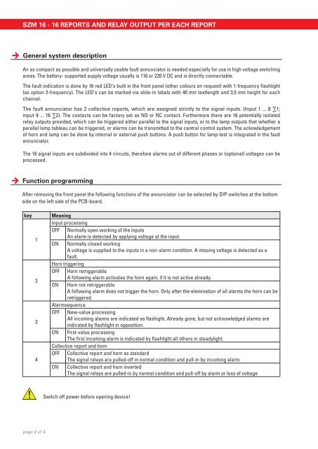
Function programming<br />
After removing the front panel the following functions of the annunciator can be selected by DIP-switches at the bottom<br />
side on the left side of the PCB-board.<br />
key Meaning<br />
Input processing<br />
OFF Normally open working of the inputs<br />
1<br />
ON<br />
An alarm is detected by applying voltage at the input.<br />
Normally closed working<br />
A voltage is supplied to the inputs in a non-alarm condition. A missing voltage is detected as a<br />
fault.<br />
Horn triggering<br />
OFF Horn retriggerable<br />
2<br />
ON<br />
A following alarm activates the horn again, if it is not active already.<br />
Horn not retriggerable<br />
A following alarm does not trigger the horn. Only after the elemination of all alarms the horn can be<br />
retriggered.<br />
Alarmsequence<br />
OFF New-value processing<br />
3<br />
All incoming alarms are indicated as flashight. Already gone, but not acknowledged alarms are<br />
indicated by flashlight in opposition.<br />
ON First-value processing<br />
The first incoming alarm is indicated by flashlight all others in steadylight.<br />
<strong>Co</strong>llective report and horn<br />
OFF <strong>Co</strong>llective report and horn as standard<br />
4<br />
The signal relays are pulled-off in normal condition and pull-in by incoming alarm.<br />
ON <strong>Co</strong>llective report and horn inverted<br />
The signal relays are pulled-in by normal condition and pull-off by alarm or loss of voltage<br />
page 2 of 4<br />
Switch off power before opening device!