SZM 16 - EES Elektra Elektronik GmbH & Co. Störcontroller KG
SZM 16 - EES Elektra Elektronik GmbH & Co. Störcontroller KG
SZM 16 - EES Elektra Elektronik GmbH & Co. Störcontroller KG

Create successful ePaper yourself
Turn your PDF publications into a flip-book with our unique Google optimized e-Paper software.
30.06.2010<br />
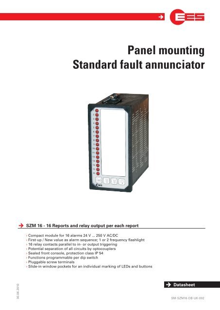
Panel mounting<br />
Standard fault annunciator<br />
<strong>SZM</strong> <strong>16</strong> - <strong>16</strong> Reports and relay output per each report<br />
› <strong>Co</strong>mpact module for <strong>16</strong> alarms 24 V ... 250 V AC/DC<br />
› First-up / New value as alarm sequence; 1 or 2 frequency flashlight<br />
› <strong>16</strong> relay contacts parallel to in- or output triggering<br />
› Potential separation of all circuits by optocouplers<br />
› Sealed front console, protection class IP 54<br />
› Functions programmable per dip switch<br />
› Pluggable screw terminals<br />
› Slide-in window pockets for an individual marking of LEDs and buttons<br />
Datasheet<br />
SM-<strong>SZM</strong><strong>16</strong>-DB-UK-002
<strong>SZM</strong> <strong>16</strong> - <strong>16</strong> RepoRtS anD Relay output peR each RepoRt<br />
General system description<br />
An as compact as possible and universally usable fault annunciator is needed especially for use in high voltage switching<br />
areas. The battery- supported supply voltage usually is 110 or 220 V DC and is directly connectable.<br />
The fault indication is done by <strong>16</strong> red LED‘s built in the front panel (other colours on request) with 1-frequency flashlight<br />
(as option 2-frequency). The LED‘s can be marked via slide-in labels with 40 mm textlength and 3,5 mm height for each<br />
channel.<br />
The fault annunciator has 2 collective reports, which are assigned strictly to the signal inputs. (Input 1 ... 8 ∑1;<br />
input 9 ... <strong>16</strong> ∑2). The contacts can be factory set as NO or NC contact. Furthermore there are <strong>16</strong> potentially isolated<br />
relay outputs provided, which can be triggered either parallel to the signal inputs, or to the lamp outputs that whether a<br />
parallel lamp tableau can be triggered, or alarms can be transmitted to the central control system. The ackowledgement<br />
of horn and lamp can be done by internal or external push buttons. A push button for lamp-test is integrated in the fault<br />
annunciator.<br />
The <strong>16</strong> signal inputs are subdivided into 4 circuits, therefore alarms out of different phases or (optional) voltages can be<br />
processed.<br />
Function programming<br />
After removing the front panel the following functions of the annunciator can be selected by DIP-switches at the bottom<br />
side on the left side of the PCB-board.<br />
key Meaning<br />
Input processing<br />
OFF Normally open working of the inputs<br />
1<br />
ON<br />
An alarm is detected by applying voltage at the input.<br />
Normally closed working<br />
A voltage is supplied to the inputs in a non-alarm condition. A missing voltage is detected as a<br />
fault.<br />
Horn triggering<br />
OFF Horn retriggerable<br />
2<br />
ON<br />
A following alarm activates the horn again, if it is not active already.<br />
Horn not retriggerable<br />
A following alarm does not trigger the horn. Only after the elemination of all alarms the horn can be<br />
retriggered.<br />
Alarmsequence<br />
OFF New-value processing<br />
3<br />
All incoming alarms are indicated as flashight. Already gone, but not acknowledged alarms are<br />
indicated by flashlight in opposition.<br />
ON First-value processing<br />
The first incoming alarm is indicated by flashlight all others in steadylight.<br />
<strong>Co</strong>llective report and horn<br />
OFF <strong>Co</strong>llective report and horn as standard<br />
4<br />
The signal relays are pulled-off in normal condition and pull-in by incoming alarm.<br />
ON <strong>Co</strong>llective report and horn inverted<br />
The signal relays are pulled-in by normal condition and pull-off by alarm or loss of voltage<br />
page 2 of 4<br />
Switch off power before opening device!
panel MountinG StanDaRD Fault annunciatoR<br />
Standard design<br />
• 1-frequency flashlight<br />
• All switches are in OFF position<br />
• Triggering of relays outputs is done parrallel to inputs<br />
• Relay contacts are designed as NO-contact<br />
Options<br />
• 2-frequency flashlight -- fast flashlight / steady light / slow flashlight<br />
• ∑2 is replaced by a second horn priority - input 1 ... 8 assigned to horn H1<br />
input 9 ... <strong>16</strong> assigned to horn H2<br />
• All relay contacts designed as NC-contacts<br />
• Alternative use of collective reports - <strong>Co</strong>llective report for input 1 ... <strong>16</strong><br />
Live-<strong>Co</strong>ntact (NC)<br />
• BSV-Soft - Label patterns for MS-Word<br />
technical data<br />
Electrical data<br />
Type <strong>SZM</strong><strong>16</strong>-24/60 <strong>SZM</strong><strong>16</strong>-110/110 <strong>SZM</strong><strong>16</strong>-220/125<br />
<strong>SZM</strong><strong>16</strong>-220/220<br />
<strong>SZM</strong><strong>16</strong>-220/220L<br />
<strong>SZM</strong><strong>16</strong>-230/230<br />
Item number 57<strong>SZM</strong><strong>16</strong>001 57<strong>SZM</strong><strong>16</strong>00F 57<strong>SZM</strong><strong>16</strong>00H<br />
57<strong>SZM</strong><strong>16</strong>00J<br />
57<strong>SZM</strong><strong>16</strong>00J2<br />
57<strong>SZM</strong><strong>16</strong>00U<br />
Supply voltage<br />
24 V AC/DC<br />
± 20 %<br />
48 ... 110 V DC<br />
± 20 %<br />
125 ... 220 V DC<br />
± 10 %<br />
125 ... 220 V DC<br />
± 10 %<br />
230 V AC<br />
+10 / -15 %<br />
Power consumption max. 10 W max. 10 W max. 10 W max. 10 W max. 10 W<br />
24 ... 60 V 85 ... 125 V 100 … 150 V 185 ... 250 V 185 ... 250 V<br />
Signal voltage<br />
AC/DC<br />
AC/DC<br />
AC/DC<br />
AC/DC<br />
AC/DC<br />
+10 / -15 % +10 / -15 % +10 / -15 % +10 / -15 % +10 / -15 %<br />
Response threshold<br />
approx. <strong>16</strong> V<br />
maximal 70 V<br />
approx. 70 V<br />
maximal 140 V<br />
approx. 85 V<br />
maximal <strong>16</strong>5 V<br />
approx. <strong>16</strong>0 V<br />
maximal 250 V<br />
approx. <strong>16</strong>0 V<br />
maximal 250 V<br />
Response delay approx. 100 ms approx. 100 ms approx. 100 ms approx. 100 ms approx. 100 ms<br />
Max. input current per<br />
indicator contact<br />
approx. 4 mA approx. 2.5 mA approx. 2.5 mA approx. 1.5 mA approx. 1.5 mA<br />
Terminal voltage SELV / PELV acc. to DIN EN 60950-1:2006-11 / DIN EN 50178:1998-04<br />
DIN EN 60664-1:2008-01 (Isolation)<br />
Inputs / Supply / Outputs 4 kV<br />
Alternating voltage All circuits except relay contacts against each other 4,0 kV 50 Hz / 1min<br />
dielectric strength<br />
Interference emission DIN EN 61000-3-2:2006-10<br />
DIN EN 61000-3-3:2006-06<br />
DIN EN 55011:2007-11 Class B<br />
Interference strength DIN EN 61000-6-2:2006-03<br />
DIN EN 61000-4-2:2001-12 (Static discharge ESD)<br />
8 kV / 4 kV<br />
DIN EN 61000-4-3:2008-06 (Electromagnetic fields)<br />
10 V/m 80 – 1000 MHz<br />
DIN EN 61000-4-4:2005-07 (Burst)<br />
L, N 2 kV;<br />
other 4 kV capacitive<br />
DIN EN 61000-4-5:2007-06 (Surge)<br />
L, N, Outputs 1 kV / 2 kV;<br />
Inputs 4 kV<br />
DIN EN 61000-4-6:2008-04 (<strong>Co</strong>nducted Interference strength)<br />
10 V 150 kHz – 80 MHz<br />
DIN EN 61000-4-11:2005-02 (Voltage break downs)<br />
Whole device DIN EN 50178:1998-04 / DIN EN 60950-1:2006-11<br />
page 3 of 4
<strong>SZM</strong> <strong>16</strong> - <strong>16</strong> RepoRtS anD Relay output peR each RepoRt<br />
Flashing frequency<br />
Fast flashing approx. 1 Hz<br />
Slow flashing approx. 0.25 Hz<br />
Load on relay contacts 24 ... 250 V AC 2 A; 110 V DC 0.5 A; 220 V DC 0.3 A<br />
Mechanical data<br />
Housing MBS ( fibre reinforced Noryl )<br />
Front frame 72 x 144 mm; max. installation depth 158 mm<br />
Panel cut-off 66 x 138 + 1 mm<br />
Installation aribitrary<br />
Weight approx. 1.1 kg<br />
Ambient conditions<br />
Ambient temperature -20 °C ... +60 °C without condensation<br />
Storage temperature -20 °C ... +70 °C without condensation<br />
Protection class front IP 54<br />
Protection class back IP 20<br />
Terminals pluggable<br />
Wire cross-section rigid or flexible<br />
Without wire sleeves 0,2 … 2,5 mm 2<br />
With wire sleeves 0,25 … 2,5 mm 2<br />
Humidity 75 % on average over the year, relative humidity<br />
On 56 days up to 93 % relative humidity, condensation not permitted in operation<br />
[Inspection: 40°C, 93 % rh > 4 days]<br />
contact<br />
Standard assignment<br />
1-frequency flash light<br />
F1 – Acknowlegement horn<br />
F2 – Acknowlegement Flashlight<br />
F3 – not assignend<br />
2-frequency flash light<br />
F1 – Acknowlegement horn<br />
F2 – Acknowlegement Flashlight fast<br />
F3 – Acknowlegement Flashlight slow<br />
Version <strong>SZM</strong><strong>16</strong>-220/220L<br />
<strong>Co</strong>llective report 1 = CR for Input 1 … <strong>16</strong><br />
<strong>Co</strong>llective report 2 = Live-<strong>Co</strong>ntact (NC)<br />
<strong>Elektra</strong> <strong>Elektronik</strong> <strong>GmbH</strong> & <strong>Co</strong> <strong>Störcontroller</strong> <strong>KG</strong> | Hummelbühl 7-9 | 71522 Backnang | Germany<br />
Tel. +49 (0) 7191.182-0 | Fax. +49 (0) 7191.182-200 | info@ees-online.de | www.ees-online.de<br />
Dimension in mm<br />
Subject to changes without prior notice